Modeling Behavior in a Simple State Machine
Overview
Before you can run a simulation using Moxie, you need to create a state machine to describe the behavior of your system. If you are not familiar with the concept of a state machine, you may want to read the introductory paragraphs of the state machines section in the SysML Modeling Reference. In this section, you will create a simple SysML state machine to model the behavior of powering on the UAV.
This section covers the following concept:
- State machines and state machine diagrams
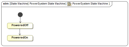
Figure A1: A simple state machine
Prerequisites
| Prerequisite | Description |
|---|---|
| Moxie Installation | You must have installed Moxie. |
| Tutorial Project | You must start this section with the Moxie simulation project from the previous section. If you did not complete the previous section, you can use the following project from the Moxie installation: \documentation\tutorialFiles\01\InstanceSpecificationDiagrams.mdzip |
| Recommended Reading |
Before completing this section, you may want to read the following help topics:
|
Instructions
A state machine diagram is a graphical interface for viewing and updating its corresponding state machine. Creating a state machine diagram also conveniently creates the corresponding state machine for you.
- Open the project from the previous section.
-
In the Containment Tree,
right-click the Structure >
PowerSystemblock and select Create Diagram (or press ). -
Select SysML State Machine Diagram,
enter
PowerSystem State Machineas its name, and press . You may need to click the button in the lower left of the dialog in order to find SysML State Machine Diagram. -
In the state machine diagram, you should see an initial pseudostate with a transition to a blank state.
The UAV should start in a powered-off state,
so double-click the state on the diagram to bring up its specification window,
enter
PoweredOffas its name, and click . -
Select the
PoweredOffstate in the diagram and click the Transition button ( ) on the context toolbar next to the state.
Then click anywhere on the canvas to add a new state.
) on the context toolbar next to the state.
Then click anywhere on the canvas to add a new state.
-
Double-click the new state on the diagram to bring up its specification window.
Enter
PoweredOnas its name and click .Figure B1: The power system state machine
- Save your work before continuing.
This state machine only describes a power system being in a powered-off state and then being in a powered-on state. It does not describe the transition between the two states — neither the time at which the transition occurs, nor the effect the transition has on the underlying properties of the system.
To learn more about state machine concepts, see the state machines help topic.
Next Section >