Creating Reactive Transitions with Change Events
Overview
In addition to call events and time events, another way to initiate behaviors in a Moxie simulation is through change events.
A change event evaluates a boolean expression over time
and triggers its transition when the expression changes from false to true.
In this section, you will use a change event to have the computer detect when the power is on
and then instruct the flight controller to arm (unlock the safety on) the UAV's motors.
This section covers the following concept:
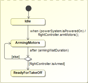
Figure A1: A change event
Prerequisites
| Prerequisite | Description |
|---|---|
| Moxie Installation | You must have installed Moxie. |
| Tutorial Project | You must start this section with the Moxie simulation project from the previous section. If you did not complete the previous section, you can use the following project from the Moxie installation: \documentation\tutorialFiles\02\CompositeStates.mdzip |
| Recommended Reading |
Before completing this section, you may want to read the following help topic:
|
Instructions
Add arming-related properties and an operation
- Open the project from the previous section.
-
In the System Definition (the BDD),
select the
FlightControllerblock, click the Create Element button ( ) on the upper-right corner of the block,
and select Value Property.
) on the upper-right corner of the block,
and select Value Property.
-
Enter
isArmed : Boolean = falseas the property's name, type, and default value. - Double-click the new property, set the Visibility to public, and click . You may need to select Expert in the Properties filter in the upper right of the window in order to find the Visibility property.
-
Select the
FlightControllerblock again, click the Create Element button () on the upper-right corner of the block,
and select Operation
(or press ).
-
Enter
armMotorsas the operation's name. - Double-click the new operation, set the Visibility to public, and click .
-
Select the
Computerblock, click the Create Element button () on the upper-right corner of the block,
and select Part Property.
-
Enter
armingWaitDuration : FixedDurationas the property's name and type. - Double-click the new property, set the Visibility to private, and click .
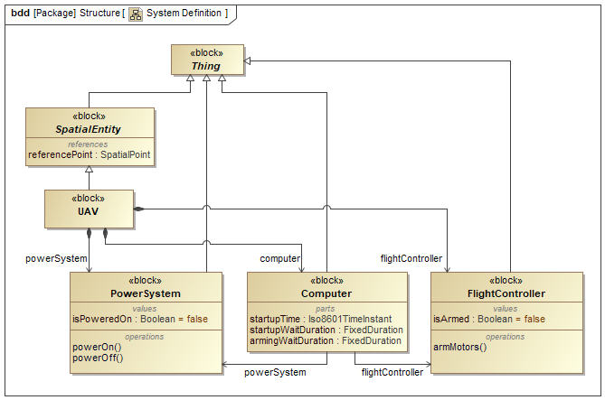
Figure B1: The system definition (BDD)
Set the properties in the instance specifications
-
In the Instance Specification Diagram,
double-click the
FlightControllerinstance specification and select Slots from the left pane of the specification window. -
In the center pane,
select the
isArmedslot and click . -
Ensure the value is set to
falseand click . -
In the Containment Tree,
right-click the Moxie-Base > Structure >
FixedDurationblock and select Tools > Create Instance.... -
In the 1. Select parts page,
set the
secondsvalue to5and click . - In the 2. Select a package page, select the Simulation package and click .
- In the 3. Create a diagram page, clear the Create a new diagram checkbox and click .
-
In the Containment Tree,
rename the new
fixedDurationinstance specification toarmingWaitDuration. -
Drag the Simulation >
armingWaitDurationinstance specification from the Containment Tree into theuav.computerinstance specification on the diagram and click . -
(Optional)
Click the Link button (
 ) on the context toolbar next to the
armingWaitDurationinstance specification. Then click on theuav.computerinstance specification to add the link.
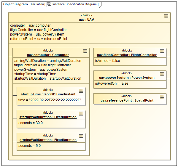
Figure B2: The instance specification diagram
Add a call event to the flight controller state machine
-
In the FlightController State Machine diagram,
select Choice from the toolbar to the left of the canvas,
click the transition from
IdletoReadyForTakeoff, and then click either or . -
Double-click the transition from the choice pseudostate to the
ReadyForTakeoffstate, set the Guard to the stringisArmed, and click . -
Select the choice pseudostate,
click the Transition button (
 ) on the context toolbar,
and then click the
) on the context toolbar,
and then click the Idlestate. -
Double-click the new transition,
set the Guard to the string
else, and click . -
Double-click the transition from the
Idlestate to the choice pseudostate. - In the Trigger category, set the Event Type to CallEvent.
-
Set the Operation to
armMotors(). - In the Effect category, set the Behavior Type to Opaque Behavior.
-
Set the Body and Language to the string
isArmed = true;, (optionally) add a line break beforeisArmed = true;, and click .
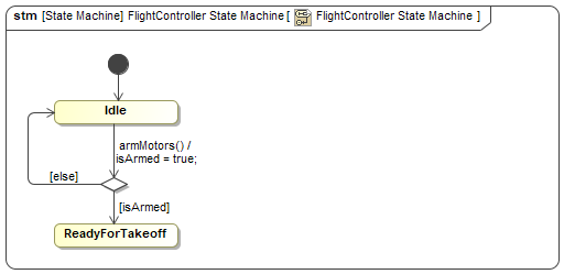
Figure B3: The flight controller state machine
Add a change event to the computer state machine
-
In the Computer State Machine diagram,
select State from the toolbar to the left of the canvas,
click the transition from
IdletoReadyForTakeoff, and then click either or . -
Enter
ArmingMotorsas the new state's name. -
Double-click the transition from
IdletoArmingMotors. - In the Trigger category, set the Event Type to ChangeEvent.
-
Set the Change Expression to the string
powerSystem.isPoweredOn, - In the Effect category, set the Behavior Type to Opaque Behavior.
-
Set the Body and Language to the string
flightController.armMotors();, (optionally) add a line break beforeflightController.armMotors();, and click .
Create a choice that checks the result
-
Select Choice from the toolbar to the left of the canvas,
click the transition from
ArmingMotorstoReadyForTakeoff, and then click either or . -
Double-click the transition from the choice pseudostate to the
ReadyForTakeoffstate, set the Guard to the stringflightController.isArmed, and click . -
Select the choice pseudostate,
click the Transition button () on the context toolbar,
and then click the
ArmingMotorsstate. -
Double-click the new transition,
set the Guard to the string
else, and click . -
Double-click the transition from the
ArmingMotorsstate to the choice pseudostate. - In the Trigger category, set the Event Type to TimeEvent.
-
Enter
armingWaitDurationfor When, set Is Relative totrue, and click . -
Run (
 ) the simulation
and observe that the second region of the computer's composite state remains in the
) the simulation
and observe that the second region of the computer's composite state remains in the Idlestate until thepowerSystem.isPoweredOnproperty changes totrue.Figure B4: The second computer state machine region
- Save your work before continuing.
Next Section >