Handling Multiplicity in State Machines
Overview
Multiplicity defines the number of instances that can exist for a given part or reference property.
For example, assume the UAV in this tutorial is a quadcopter with exactly four distinct motors: one to power each propeller.
This translates to a multiplicity of 4..4 (minimum of 4 and maximum of 4) in SysML.
In this section, you will use a repeating substate to have the flight controller arm each motor one by one.
This section covers the following concepts:
- Multiplicity
- State entry and exit behaviors
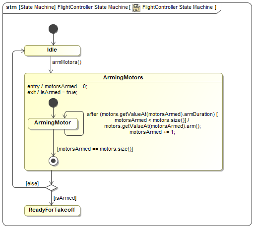
Figure A1: Iterating through a property with multiplicity greater than one
Prerequisites
| Prerequisite | Description |
|---|---|
| Moxie Installation | You must have installed Moxie. |
| Tutorial Project | You must start this section with the Moxie simulation project from the previous section. If you did not complete the previous section, you can use the following project from the Moxie installation: \documentation\tutorialFiles\02\ChangeEvents.mdzip |
| Recommended Reading |
Before completing this section, you may want to read the following help topic:
|
Instructions
Create a block for the motors
- Open the project from the previous section.
-
In the System Definition (the BDD),
select the
Thingblock, click the downward-pointing Generalization button ( ) on the context toolbar,
and then click anywhere on the canvas to add a new block.
) on the context toolbar,
and then click anywhere on the canvas to add a new block.
-
Select the new block on the diagram
and enter
Motoras its name. -
Click the Create Element button (
 ) on the upper-right corner of the block
and select Part Property.
) on the upper-right corner of the block
and select Part Property.
-
Enter
armDuration : FixedDurationas the property's name and type. - Double-click the new property, set the Visibility to public, set the Aggregation to shared, and click .
-
Select the
Motorblock again, click the Create Element button () on the upper-right corner of the block,
and select Operation
(or press ).
-
Enter
armas the operation's name. - Double-click the new operation, set the Visibility to public, and click .
Assign the block to properties
The Motor block should be a part property of the UAV and reference property of the flight controller,
with a multiplicity of four in both cases, indicating that there are exactly four motors for a single UAV and flight controller.
-
Select the
UAVblock, click the Directed Composition button ( ) on the context toolbar,
and then click the
) on the context toolbar,
and then click the Motorblock. -
Double-click the new association
and in the Role of Motor category,
set the Name to
motorsand the Multiplicity to4. -
In the Role of UAV category,
set the Multiplicity to
1and click . -
In the toolbar to the left of the BDD canvas,
select Directed Association,
click the
FlightControllerblock, and then click theMotorblock. -
Double-click the new association
and in the Role of Motor category,
set the Name to
motorsand the Multiplicity to4. -
In the Role of FlightController category,
set the Multiplicity to
1and click . -
Select the
FlightControllerblock, click the Create Element button () on the upper-right corner of the block,
and select Value Property.
-
Enter
motorsArmed : Integeras the property's name and type. - Double-click the new property, set the Visibility to private, and click .
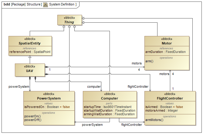
Figure B1: The system definition (BDD)
Create instance specifications for the motors
The four motors each need their own instance specification.
However, assuming they are identical, they will all take the same amount of time to arm,
so they can share a single armDuration instance specification.
-
Right-click the
Motorblock and select Tools > Create Instance.... -
In the 1. Select parts page,
select the
armDurationproperty, click the cell to the right of Value, and then click the button in the right corner of the cell. -
Select the Simulation >
armingWaitDurationinstance specification, click , and then click . - Set the Name to the string armDuration and click , , and then .
- In the 2. Select a package page, select the Simulation package and click .
- In the 3. Create a diagram page, clear the Create a new diagram checkbox and click .
-
In the Containment Tree,
set the
secondsvalue of the newarmDurationinstance specification to3. -
Copy () the
motorinstance specification, select the Simulation package, and paste () the instance specification three times. -
Rename the four motor instance specifications to
uav.frontLeftMotor,uav.frontRightMotor,uav.rearLeftMotor, anduav.rearRightMotor.
Assign the instance specifications to properties
- Open the Instance Specification Diagram.
-
Drag the the four motor instance specifications
from the Containment Tree
into the
uavinstance specification on the diagram and click for each of them. -
For each motor instance specification:
Select it, click the Link button ( ) on the context toolbar,
click on the
) on the context toolbar,
click on the uavinstance specification to add the link, and then click on both pages of the dialog window. -
Double-click the
uav.flightControllerinstance specification and select Slots from the left pane of the specification window. -
In the center pane,
select the
motorsslot and click . -
Click ,
then the Add Recursively button (
 ) to add all four motor instance specifications,
and then and .
) to add all four motor instance specifications,
and then and .
-
Drag the Simulation >
armDurationinstance specification from the Containment Tree into theuavinstance specification on the diagram. -
(Optional)
For each motor instance specification:
Select it, click the Link button () on the context toolbar,
and then click on the armDurationinstance specification to add the link.
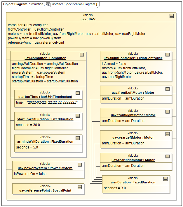
Figure B2: The instance specification diagram
Create a state with entry and exit behaviors
States can activate behaviors upon entry and exit just like transitions activate behaviors in their effects. These entry and exit behaviors activate regardless of which transitions are taken into and out of the state. Also like with transition effects, Moxie requires these behaviors to be opaque behaviors with bodies written as opaque expressions.
-
In the FlightController State Machine diagram,
select State from the toolbar to the left of the canvas,
click the transition from the
Idlestate to the choice pseudostate, and then click . -
Enter
ArmingMotorsas the new state's name. -
Double-click the transition from
IdletoArmingMotors. - In the Effect category, set the Behavior Type to <UNSPECIFIED> and click .
-
Double-click the
ArmingMotorsstate. - In the Entry category, set the Behavior Type to OpaqueBehavior.
-
Set the Body and Language to the string
motorsArmed = 0;. - In the Exit category, set the Behavior Type to OpaqueBehavior.
-
Set the Body and Language to the string
isArmed = true;and click .
Model the internal behavior with a repeating substate
Similarly to how you modeled simultaneous behavior by nesting states inside a composite superstate, you can model the internal behavior of a state by nesting substates inside of it.
-
In the toolbar to the left of the state machine canvas,
select Initial
and click in the
ArmingMotorsstate to add an initial pseudostate. -
Click the Transition button (
 ) on the context toolbar,
right-click in the state and select State,
and then enter
) on the context toolbar,
right-click in the state and select State,
and then enter ArmingMotoras its name. -
Click the Transition button () on the context toolbar again.
Then right-click in the state and select Final State to add a final pseudostate.
-
Select the
ArmingMotorstate again, click the Transition button () on the context toolbar,
and click the ArmingMotorstate (or click the Transition to Self button ( )).
)).
-
Double-click the transition-to-self on the
ArmingMotorstate. -
In the Trigger category,
set the Event Type to TimeEvent,
set When to the string
motors.getValueAt(motorsArmed).armDuration, and set Is Relative totrue. -
Set the Guard to the string
motorsArmed < motors.size()and (optionally) add a line break beforemotorsArmed < motors.size(). -
In the Effect category,
set the Behavior Type to OpaqueBehavior,
set the Body and Language to the string
motors.getValueAt(motorsArmed).arm(); motorsArmed += 1;, and (optionally) add line breaks beforemotors.getValueAt(motorsArmed).arm();andmotorsArmed += 1;. Then click . -
Double-click the transition from the
ArmingMotorstate to the final pseudostate, set the Guard to the stringmotorsArmed == motors.size(), and click . -
Run (
 ) the simulation
and observe that the flight controller arms the motors one by one before setting itself as ready for takeoff.
) the simulation
and observe that the flight controller arms the motors one by one before setting itself as ready for takeoff.
Figure B3: The flight controller state machine
- Save your work before continuing.
Next Tutorial!