STK Aviator
STK Professional and Aviator.
The results of the tutorial may vary depending on the user settings and data enabled (online operations, terrain server, dynamic Earth data, etc.). It is acceptable to have different results.
Watch the following video, then follow the steps below incorporating the systems and missions you work on (sample inputs provided).Use Aviator to create a Gunship short takeoff from a cleared airstrip to a target and return to the airstrip and land. This lesson can be completed with or without an Internet connection. In this lesson, you will be required to enter multiple latitudes and longitudes. Please keep in mind that Place, Target, and Facility objects can be simply inserted using point-and-click in the 2D Graphics window or employing the 3D Object Editing Tool in the 3D Graphics window. Typing all the data in this lesson ensures you obtain the same data and feedback.
Create a Scenario
Start by creating a scenario.
- Launch STK (
 ).
). - Create a scenario and name it Aviator.
- Change Start: to 1 Jul 2016 16:00:00.000 UTCG.
- Change Stop: to + 6 hr.
- Click OK.
Save Often!
Scenario Level Properties
Disable Terrain Server.
- Open Aviator's (
 ) properties (
 ).
). - Browse to the Basic - Terrain page.
- Disable Use terrain server for analysis.
- Click Apply.
Set the Reference to Mean Sea Level
Aviator performs best in the 3D Graphics window when the surface reference of the globe is set to Mean Sea Level. You will receive a warning message when you apply changes or click OK to close the properties window of an Aviator object with the surface reference set to WGS84. It is highly recommended that you set the surface reference as indicated before working with Aviator.
- Browse to the 3D Graphics - Global Attributes page.
- In the Surface At field, under Surface Reference of Earth Globes, select Mean Sea Level from the drop-down menu.
Enable Surface Lines
Surface Lines can be displayed in the 3D Graphics window on the surface of the central body when terrain data is available.
- In the Surface Lines field, enable On Terrain.
- Click OK.
3D Graphics Window Properties
To help you when orienting your view in the 3D Graphics window, you can have object labels "float" above the terrain and use an embedded compass.
- Bring the 3D Graphics window to the front.
- Right-click on the 3D Graphics window and select Properties.
- On the Details page, find Label Declutter and turn on Enable.
- Browse to the Annotation page.
- Locate Compass and enable Show.
- Click OK.
When you return to the 3D Graphics window, in the lower left corner of the window there is a small compass. When you start to add objects to the scenario the object labels will float above the terrain.
Add Terrain for Analysis and Visualization
You can add analytical and visual terrain using Globe Manager.
- Bring the 3D Graphics window to the front and click Globe Manager (
 ).
). - In Globe Manager, click Add Terrain/Imagery (
 ).
). - Click the ellipses button.
- Browse to <STK Instal directory>\Help\stktraining\imagery.
- Click OK.
- Open the PtMugu_ChinaLake.pdtt file.
- Select Yes in the Use Terrain for Analysis pop up window.
Create an Airstrip
You don't have an airfield or airstrip that can be loaded from the ARINC424 runways database (FAANFD18). If you don't have Bing Maps or a satellite image of a cleared airstrip, a simple way to build one on top of the terrain is by using an Area Target object.
You will be outlining a private airfield but this technique could be used to outline an airstrip in the middle of a desert. If you don't have an Internet connection, Bing Maps, or a satellite picture of the airstrip, outlining it with an Area Target object is a good way to obtain situational awareness of the airstrip's size and location. The Area Target can be precisely drawn if you have the coordinates or you can click and draw using the 2D Graphics window or the 3D Object Editing tool.
- Insert an Area Target (
 ) object using the Insert Default method.
 - Rename the Area Target object Airstrip.
- Open Airstrip's () properties ().
- On the Basic - Boundary page, insert the following points (copy and paste if able):
- Click Apply.
| Latitude | Longitude |
|---|---|
| 35.74833 deg | -117.63113 deg |
| 35.74835 deg | -117.63107 deg |
| 35.73713 deg | -117.62753 deg |
| 35.73711 deg | -117.6276 deg |
Make the airstrip easier to see in the 2D Graphics window.
- Browse to the 2D Graphics - Attributes page.
- If desired, change the color.
- Use the heaviest line width.
- Click OK.
- Bring the 3D Graphics window to the front and Zoom To Airstrip.
- Use your mouse to obtain a good view of Airstrip.
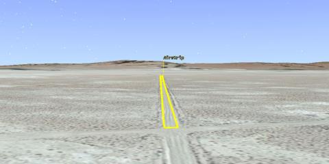
3D Graphics Airstrip View
Create a Navigation Point
When you enter the target area, the navigation point will be used to line up the circular flight orbit around a ground target.
- Insert a Place (
 ) object using the Define Properties () method.
 - Enter the following values:
- Click OK.
- Rename the Place object "NavPoint."
| Latitude | Longitude |
|---|---|
| 34.8977 deg | -117.6446 deg |
Add a Target
This is a practice target that the gunship will use to calibrate its instruments.
- Insert a Target (
 ) object using the Define Properties () method.
 - Browse to the 3D Graphics - Model page.
- Enable Model - Show.
- In the Detail Thresholds field, change Details - Maximum Viewing Distance - All by moving the slider all the way to the right (maximum distance).
- Click OK.
- Rename the Target object "GndTarget."
| Option | Value |
|---|---|
| Latitude | 34.8979 deg |
| Longitude | -117.6857 deg |
| Height Above Ground | 1 m |
3D Aviator Editing
Add an Aircraft object to the scenario and then edit its performance models using the Aviator Editing toolbar. This toolbar allows you to define an aircraft and its procedures directly in the 3D Graphics window. When airfield or airstrip data doesn't exist in a file format, this procedure will be the most accurate means of building takeoff and landing procedures. In this scenario, use a combination of the Aviator Editing toolbar and object properties. The aircraft will have a light fuel load due to the short takeoff required at the airstrip.
- Insert an Aircraft (
 ) object using the Insert Default () method.
 - Rename the Aircraft object "GunShip".
Enable the 3D Aviator Editing Tool
Enable the 3D Aviator Editing tool using the following steps.
- Extend the View menu.
- Extend the Toolbars menu and select the 3D Aviator Editing tool.

3D Aviator Editing Tool
Zoom To the Aircraft
- Focus on the 3D Graphics window and Zoom To Airstrip and center your view on the center of the runway. Simply use the Area Target object's centroid.
- Select Aircraft/GunShip in the 3D Object Editing toolbar Object Selection drop-down list.
- Click the Object Edit Start/Accept (
 ) button to start the 3D Object Editing tool.
 - Click the Switch to Aviator button on the 3D Aviator Editing tool.
- Click OK when the warning window pops up.
Select the Aircraft Type
First you will select the aircraft type and then edit its performance models.
- In the 3D Aviator Editing tool, click the Select Aircraft (
 ) button.
 - When the Select Aircraft window pops up, right click on Basic Military Transport and select Duplicate.
- Select Copy of Basic Military Transport and rename it "GunShip."
- Click OK.
Performance Models
Change a couple performance models for familiarization of the GUI.
- In the 3D Aviator Editing tool, click the Aircraft Catalog for Current Aircraft (
 ) button.
 - In Performance Models:, select the Acceleration Built-In Model.
- Change the Bank Angle: to 20 deg.
- Select the Cruise Built-In Model.
- Change the Default Cruise Altitude: to 10000 ft.
- Click Save and then Close.
You can browse through the Basic Performance models to familiarize yourself with their Built-in Models. There are Advanced Performance models that can be added to the scenario. However, in this tutorial, use Basic Performance Models.
Adjust the Position of the Aircraft
Line the aircraft up with the runway for the Takeoff Procedure.
- Make sure you are zoomed into the runway. North should be pointing up.
- Return to the Aviator Editing toolbar.
- Choose Runway in the Aviator site pull down window.
- Choose Takeoff in the Aviator Procedure pull down window.
- Using the mouse, shift-click on Airstrip's centroid.
- Scroll out far enough to see one red ball at both ends of the Takeoff procedure.
- Place the cursor on the Takeoff @ Runway - WheelsRelease red ball (most likely the red ball to the west), hold down the left mouse button, and drag and drop the red ball at the runway threshold. The runway threshold is the north end of the airstrip.
Use the 3D Object Editing and 3D Aviator Editing toolbars to create a flight route to include takeoff and landing. STK can utilize DAFIF or the Digital Aeronautical Flight Information Files.
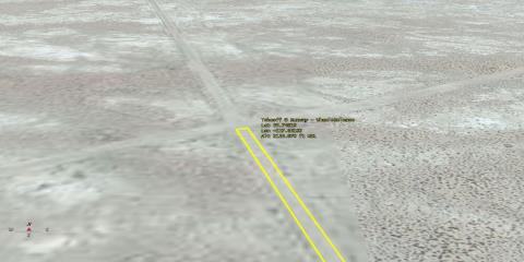
Runway Threshold
Modify the Aircraft's Runway Placement
Depending on how precise your clicks were in the 3D Graphics window, the Aircraft object's model could be above or below the surface of the map. Either way, instruct the Aircraft object to follow the terrain during the takeoff roll. Furthermore, compensate for the wheels to ensure, visually, that the wheels are touching the runway.
- Click the Modify Procedure (
 ) button in the 3D Aviator Editing tool.
 - Make the following changes in the Takeoff Properties pop up window:
- Click OK.
- Click the Object Edit Start/Accept (
 ) button to accept the changes.
 - Zoom to the Aircraft object.
- If required, using the 3D Object Editing tool and the 3D Aviator Editing tool, continue to adjust the takeoff procedure until satisfied with the Aircraft object's alignment.
- Once satisfied with GunShip's alignment, move to Continue Building the Flight Route.
| Option | Value |
|---|---|
| Runway Altitude Offset: | 15 ft |
| Use Terrain for Runway Altitude | On |
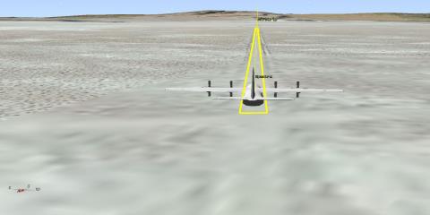
Proper Alignment
Save Airstrip to Catalog
Once you are satisfied with the takeoff procedure, save the runway to a catalog. You can use the cataloged runway when creating the landing procedure.
- Return to the 3D Graphics Editor, select Aircraft/GunShip, and click the Object Edit Start/Accept button.
- Click the Modify Site (
 ) button in the 3D Aviator Editing tool.
 - When the Runway Properties window opens, change Name: to "Airstrip."
- Click Add To Catalog and then select OK to close the Add Successful pop up window.
- Click OK to close the Runway Properties window.
- Return to the 3D Graphics Editor and click the Object Edit Start/Accept button to save your changes.
Aircraft Specifications
Since the aircraft's takeoff roll will be short it won't take a full load of fuel. It's important to set the correct fuel load and aircraft weight.
- Open GunShip's () properties ().
- In the Initial Aircraft Setup toolbar, click Configuration.
- Click Basic Configuration.
- Set the Empty Weight: to 95000 lb.
- Change the Max Landing Weight: to 155000 lb.
- Select Stations and then Internal Fuel.
- Set the Initial state: to 20000 lb and then the Capacity: to 60000 lb.
- Click Apply and then OK.
- Click Apply in GunShip's () properties ().
Mission Winds
The Wind and Atmosphere tool allows you to simulate wind and atmospheric conditions for the scenario, a mission, a specific procedure, or a group of multi-selected procedures. Since this planning session isn't taking place today, you can set up conditions based on historical values for the training area. The airstrip is located in a desert area. It's important that the correct temperature is reflected in this scenario.
- In the Initial Aircraft Setup toolbar, click Mission Wind Model.
- Using Constant Bearing/Speed, set Wind Bearing: to 200 deg and Wind Speed: to 20 nm/hr.
- Enable Atmosphere - Non Standard Surface Conditions.
- Change Sea Level Temperature: to 110 degF.
- Click OK.
- Click OK again to save your changes and to close GunShip's () properties ().
Fly to the Target
GunShip will fly from the airfield to the target, make one circle around the target, and then return and land at the airstrip.
- Return to the 3D Graphics Editor, select Aircraft/GunShip, and click the Object Edit Start/Accept button.
- Make sure you can see NavPoint in the 3D Graphics window.
- Select STK Static Object in the Aviator Site window.
- In the Select Procedure Type: window, select Holding - Circular.
- In the 3D Graphics window, Shift - Click on NavPoint.
- Click Modify Procedure.
- Make the following changes. Click Apply after changing both the hold and enroute airspeeds.
- Click Apply.
- Click OK.
- Return to the 3D Graphics Editor and click the Object Edit Start/Accept button.
| Option | Value |
|---|---|
| Hold Cruise Airspeed | Minimum Airspeed |
| Enroute Cruise Airspeed | Other Airspeed |
| Enroute Cruise Airspeed - Airspeed: | TAS - 200 nm/hr |
| Option | Value |
|---|---|
| Bearing: | 0 deg |
| Range: | 0 nm |
| Diameter: | 4 nm |
| Use Alternate Entry Points | Off |
| Turn Direction: | Outbound Left Turn |
In order to make fly a 4 nautical mile diameter holding pattern, you needed to slow down entering the pattern and then slow down some more to put weapons on the target. The key here was to ensure the left side of the plane is pointing at the target. The bearing was the direction into the holding pattern and the range of zero nautical miles meant the aircraft entered the pattern as soon as the navigation point was reached. Turning off alternate entry points ensured that the pattern began at the navigation point. There were many ways to accomplish the task. This was just one way.
Return and Land at the Airstrip
GunShip leaves the holding pattern and returns to base to land.
- Zoom to Airstrip.
- Return to the 3D Graphics Editor, select Aircraft/GunShip, and click the Object Edit Start/Accept button.
- In the 3D Aviator Editing toolbar, click the Next Procedure button to enable the holding pattern in the 3D Graphics window.
- Change the Aviator Site to Runway from Catalog and the Aviator Procedure to Landing.
- Shift-click on Airstrip's center point.
- Click the Modify Site () button and ensure the Airstrip is chosen as the Runway.
- Click the Modify Procedure () button in the 3D Aviator Editing Tool.
- In the Landing Properties window, make the following changes:
- Click OK.
- Return to the 3D Graphics Editor and click the Object Edit Start/Accept () button.
- Zoom to GunShip ().
- Use the Animation toolbar to view the flight. When viewing an Aircraft object that is propagated with Aviator, X Real-time Animation Mode (
 ) is recommended.
 - When finished, reset (
 ) the scenario.
| Option | Value |
|---|---|
| Approach Mode: | Intercept Glideslope |
| Runway Heading | Use runway heading 153 Mag 166 True (Headwind) |
| Runway Altitude Offset: | 15 ft |
| Use Terrain for Runway Altitude | On |
GunShip is lined up for a takeoff roll, flies to the target area, and lands back at the airstrip.
Create a Custom Report
Create a report that analyzes the GunShip's fight profile. The Flight Profile by Time report is a good report that provides important data such as Down Range distances and how much fuel the aircraft has consumed. As with all reports, you can customize the report with your own data.
- In the Object Browser, right-click on GunShip () and select the Report & Graph Manager (
 ).
). - In the Styles list, right-click on the Flight Profile by Time report and select Properties.
- In Report Contents field, remove Flight Profile By Time-Vertical Speed and Flight Profile By Time-Ground Speed
- Select Flight Profile By Time-Altitude-Altitude.
- In the Data Providers - Flight Profile By Time, select Altitude AGL.
- Move (
 ) Altitude AGL to the Report Contents field under Flight Profile By Time-Altitude-Altitude.
 - Click OK.
- Click OK to close the Warning message.
- In the Styles list, expand My Styles.
- Rename your report My Flight Profile by Time.
- Generate the report and view the data.
- When finished, close the report and the Report & Graph Manager.
Embed the Report in the 3D Graphics Window
You can embed the My Flight Profile by Time data in the 3D Graphics window. This is a great technique to use for briefings and making movies.
- Open GunShip's () properties ().
- Browse to the 3D Graphics - Data Display page.
- Click the Add... button.
- In the Add a Data Display pop up window, select My Flight Profile by Time and click OK.
- In the Appearance field, change Font Size: to Medium.
- Click OK.
- Bring the 3D Graphics window to the front.
- Zoom to GunShip ().
- Click the Play (
 ) button in the Animation toolbar.
 - When finished, click the Reset () button.
- Save (
 ) the scenario.
In the upper left corner of the 3D Graphics window, you can see a dynamic display of UAV's flight profile.
 Visit AGI.com