Overview
A tutorial guide to using Globe Manager features.
STK Professional. This tutorial is designed for STK users only.
The results of the tutorial may vary depending on the user settings and data enabled (online operations, terrain server, dynamic Earth data, etc.). It is acceptable to have different results.
Create a Scenario:
- Open STK and click the Create a New Scenario button.
- Enter the following in the New Scenario Wizard:
- When you finish, click OK.
- When the scenario loads, click Save (
 ). A folder with the same name as your scenario is created for you in the location specified above.
 - Verify the scenario name and location and click Save.
- Close the Insert STK Objects tool (
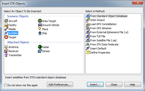 ).
). - Close the 2D Graphics window.
- Maximize the 3D Graphics window.
- Disable the Terrain Server option.
- Right-click on the scenario (
 ) and open the Properties (
 ).
). - Select the Basic - Terrain page.
- Disable the Use terrain for analysis option.
- Click OK to apply changes and dismiss the Properties Browser.
- Right-click on the scenario (
| Option | Value |
|---|---|
| Name | Globe Manager |
| Location | C:\Documents and Settings\<user>\My Documents\STK 11 (x64)\ |
| Start | Accept default start time |
| End | Accept default end time |
Using Globe Manager in STK
Adding and managing terrain and imagery
- Open Globe Manager by selecting Globe Manager (
 ) in the Globe Manager Toolbar (
 ) found at the top of the 3D Graphics Window or select the 3D Graphics Window.
 - Extend the View menu and select Globe Manager.
The Globe Manager will open and display the Hierarchy window and its associated toolbar. If not all of the buttons are visible, you may have to expand the Globe Manager pane. Some toolbar options are grayed out depending on what is selected in the Globe Manager.
Add a Set
- Select Earth in the Globe Manager, select Add Set (
 ) to create a new set, name it St. Helens and click OK.
 - With the new set selected in Globe Manager, select Add Terrain/Imagery (
 ) in the Globe Manager toolbar.
 - In the Open Imagery/Terrain Data dialog, ensure Local Files is selected on the left.
- In the Path: drop down list, ensure the directory location is set to <STK install folder>\STKData\VO\Textures. This will display all the available STK textures in that folder.
- Select St. Helens.jp2 and click Open to add the image to the set.
Zoom To St. Helens
- In the Globe Manager, click "+" next to the St. Helens set to expand it. Select St. Helens.jp2.
- Click Zoom To (
 ) in the Globe Manager toolbar or right-click on St. Helens.jp2 and select Zoom To (). The image of Mount St. Helens will now be displayed in the 3D Graphics window.
 - Clear the checkbox next to St. Helens.jp2 to turn its visibility off.
- Select the checkbox to show the image again.
Toggle Image Extents
- With the St. Helens.jp2 item selected in Globe Manager, click Toggle Extents (
 ) in the Globe Manager toolbar or right-click on St. Helens.jp2 and select Toggle Extents (). The image of Mount St. Helens will become highlighted in green, showing the extent of the image.
 - Select Toggle Extents to hide the extent.
Add the PDTT to Globe Manager
- Select the St. Helens set in Globe Manager and click Add Terrain/Imagery () in the Globe Manager toolbar.
- In the Open Imagery/Terrain Data dialog, ensure the directory location is set to <STK install folder>\STKData\VO\Textures.
- Select St. Helens.pdtt.
- Click Open.
- In the hierarchy window clear and select the imagery and terrain item checkboxes, and observe the effect of this in the 3D Graphics window.
This is the terrain file for Mount St. Helens. Using your mouse, manipulate the globe in the 3D Graphics window to view the imagery and terrain together.
Toggle Extents of a PDTT
- Select St. Helens.pdtt in the Globe Manager.
- Click Toggle Extents () in the Globe Manager toolbar or right-click on St. Helens.pdtt and select Toggle Extents ().
The pdtt of Mount St. Helens will become highlighted in green, showing the extent of the pdtt.
More information on the importation, conversion, and utilization of terrain and imagery files in STK can be found here.
Controlling render order and transparency
- In the Globe Manager, select Add Terrain/Imagery () in the Globe Manager toolbar.
- In the Path field, click the ellipsis button.
- Browse to <STK install folder>/Help/stktraining/imagery and click OK.
- Open the files named NPS_OrganPipeCactus_Map.pdttx and OrganPipeCactusNM_TerraColor_25m.jp2 to add them to Globe Manager.
Zoom To Organ Pipe
- Select OrganPipeCactusNM_TerraColor_25m.jp2 and click Zoom To () in the Globe Manager toolbar or right-click on OrganPipeCactusNM_TerraColor_25m.jp2 and select Zoom To ().
You should notice that only a small part of the NPS_OrganPipeCactus_Map image is visible under the desert image.
Change the Render Order
- Select the Render Order tab in Globe Manager.
- To bring the map image in front of the desert image select OrganPipeCactusNM_TerraColor_25m.jp2 and drag it down over the top of NPS_OrganPipeCactus_Map.pdttx until a box appears around the NPS_OrganPipeCactus_Map file name. Let go of the file and you will see that in the 3D Graphics window it is now behind the map image.
The OrganPipeCactusNM_TerraColor_25m.jp2 file appears at the top of the Render Order list. Imagery and Terrain are rendered on the globe in the order they are added to Globe Manager. Since OrganPipeCactusNM_TerraColor_25m.jp2 was the last image added, it is displayed as the top most item on the globe.
Set the Translucency
- Now return to the Hierarchy window by clicking the Hierarchy tab.
- Right-click NPS_OrganPipe_Map.pdttx and select Properties... from the drop down menu. The Properties window will appear.
- In the Translucency settings section set the Translucency to 35% and click Apply. The map graphic is now translucent and the desert imagery below it shows through. Select OK to accept the change.
Add a New Set
- Select Earth in the Globe Manager, select Add Set () to create a new set, name it Organ Pipe and click OK.
- Select both images (NPS_OrganPipeCactus_Map.pdttx and OrganPipeCactusNM_TerraColor_25m.jp2) and drag them to the newly created set.
Notice in the 3D Graphics window that the map image has again fallen below the desert image. This can occur when moving imagery around in Globe Manager. Return to the Render Order window and reorder the files to get the desired effect.
Changing the base globe and exporting and importing globe files
Globe manager allows you to save a globe as a .glb file that can be shared with other STK users and imported into other STK scenarios.
- Select Earth in the Globe Manager.
- To save the current globe, select Export Globe (
 ) in the Globe Manager toolbar.
 - Name your globe OrganPipe.glb in the Save As window that appears and select Save.
The .glb file can now be shared with other STK users and be imported into other STK scenarios.
Zoom To the Earth in 3D
- Zoom out in the 3D Graphics window to see more of the globe. For Earth, the default base image is the Earth_PE_b.jp2 file.
- To change the base image, right-click Earth in Globe Manager and select Change Base... from the pop up menu.
- In the Pick Base Texture window that appears browse to <STK install folder>/STKData/VO/Textures and select TerraMetrics_Earth_8km.jp2 from the list of available base images.
- Select Open to apply the change.
- Observe the change in the globe image in the 3D Graphics window.
Import the Globe
- Now import the globe you exported earlier by selecting Import Globe (
 ) in the Globe Manager toolbar.
 - Select Yes to dismiss the dialog.
- Browse to the directory where you exported the globe earlier, open OrganPipe.glb.
Because loading a .glb file eliminates any changes to the current globe, a window will appear asking you to confirm the change.
Managing KML Files in Globe Manager
Globe manager allows you to add KML content to a scenario.
- Select the 3D Graphics window to make it active and select Home View (
 ) in the 3D Graphics Toolbar.
 - Select the KML tab in Globe Manager.
- Select Open KML Content (
 ) in the KML toolbar.
 - Browse to <STK install folder>/Help/stktraining/KML and select the Peru_Earthquake_Dynamic_Assets.kmz file to load it into STK.
Once the KML file is loaded you will see it has populated the KML window with a table of contents.
Zoom To the Quake Region
- Right-click the Quake_Region item in the table of contents and select Zoom To from the drop-down menu. The 3D Graphics window will zoom to the Quake_Region item.
- Select the Expand button next to Quake_Region in the KML window.
- Clear the check box next to Affected Areas while viewing the 3D Window. Notice that the Affected Areas are hidden from view.
- Select the same check box to display the hidden items.
- Now select the Expand button next to Affected Areas.
- Right-click on Epicenter and select Show Balloon from the drop-down menu.
- Close the balloon.
In the 3D Graphics Window an information balloon appears containing information about the item from the KML file.
Review the Help page
- Right click on Epicenter in the KML window again and select Properties from the drop down menu.
- Select Help to view the help page describing the fields in the properties window.
- After reviewing the help page and the properties window click OK.
A properties window will open displaying a number of properties and values for the selected KML item.
Switch to List View
- Right-click anywhere in the KML window and select Switch to List View.
- Right-click again in the KML window and select Switch to Tree View.
The KML window now displays a list of all KML files added to the scenario. the Peru_Earthquake_Dynamic_Assets.kmz file will display as "AGI Analysis". The List View is useful in reducing the load time of large KML files when the tree view is not needed.
Import a New Aircraft
- Click on the Expand button next to the TurboProp_15K_Time item in the KML window.
- Right-click on one of the TurboProp_15K items that are displayed.
- Select Import as Aircraft from the drop-down menu. Notice in the Object Browser that a new Aircraft object named TurboProp_15K has been created.
Zoom To Aircraft
- Right-click on this new aircraft.
- Select Zoom To from the drop-down menu to see the object in the 3D Graphics Window.
This aircraft object can now be used like any other aircraft object within STK.
Using the Get Info Tool with KML Items
The Get Info Tool (![]() ) allows you to select an area on the 3D globe and get information on any KML items within the selected area.
) allows you to select an area on the 3D globe and get information on any KML items within the selected area.
- Select the Get Info Tool (
 ) from the KML toolbar.
 - When the Get Info Tool window appears, click Pick (
 ).
). - Click and drag a selection box over the Affected Areas in the 3D Graphics Window.
- Click the Affected Area names to view the properties and values associated with each item.
- Close the window when you have finished exploring the Get Info Tool window.
The Get Info Tool window will display information about the KML items within the selected area.
Delete the KML Content
- Bring the Globe Manager to the front.
- Select Delete KML Content (
 ) to remove the KML file from the scenario.
Managing ArcGIS Data in Globe Manager
If you are using a 32-bit version of STK and there is a licensed copy of ArcGIS on the same computer as STK you will see an ArcGIS tab in the STK Globe Manager. This allows you to incorporate GIS information into your scenario and manage its display in the 3D Graphics window. You can find more information on the Globe Manager - ArcGIS Window in our STK Help.
 Visit AGI.com