STK Professional Communications
The results of the tutorial may vary depending on the user settings and data enabled (online operations, terrain server, dynamic Earth data, etc.). It is acceptable to have different results.
Watch the following video, then follow the steps below incorporating the systems and missions you work on (sample inputs provided).Will My RF Receiver Experience Interference During a Range Test Flight?
You are on-board a stationary naval ship anchored off the west coast of the United States. The ship will participate in a missile test. A test missile will launch from a launch pad located on the Pacific Coast sending telemetry data to the communication systems on-board the ship. The data is being transmitted on a frequency which is close to a frequency being used by XM satellites. You want to determine if XM satellite transmitters will interfere with ship’s ability to receive the test missile telemetry data.
Break it Down
- The missile test will last ~ 32 minutes.
- The test missile is being launched from a launch pad located on the Pacific Coast of the United States.
- The test missile will impact into the ocean at 10 degrees latitude and 173 degrees longitude.
- The ship is receiving the test missile's telemetry data on a frequency of 2.41 GHz and a modulation of BPSK.
- The XM Satellites are transmitting on a frequency of 2.4 GHz and a modulation of QPSK.
Solution
Use STK to model a scenario that will determine if the XM satellites will interfere with the ship receiver’s ability to receive telemetry data from the test missile.
Starter Scenario
To speed things up and allow you to focus on the portion of this exercise that teaches you how to determine communication interference, a partially created scenario has been provided for you.
- Ensure that the Welcome dialog is visible in the STK Workspace.
- Click the Open a Scenario button.
- Browse to <install directory>/Help/stktraining/samples (e.g. C:\Program Files\AGI\STK 11\Help\stktraining\samples).
- Select the file MissileTest_XM_Interference.vdf.
- Click Open.
Save the Scenario
When you open the scenario, a directory with the same name as the scenario will be created in the default user directory (e.g. C:\Documents\STK 11 (x64)). The scenario will not be saved automatically. When you save a scenario in STK, it will save in the format in which it originated. In other words, if you open a Visual Data (.vdf) file, the default save format will be a VDF. The same is true for a scenario file (*.sc). If you want to save a VDF as a SC file (or vice-versa), you must change the file format when you are performing the Save As procedure.
- Open the File menu and select Save As.
- Click STK User.
- Select Missile_Test_XM_Interference and click Open.
- Change Save as type: to Scenario Files (*.sc) and click Save.
- Click Yes to confirm.
Save Often!
Insert the Test Missile
Create a missile that launches from the Pacific Coast and ditches in the ocean upon test completion.
- Using the Insert STK Objects Tool (
 ) insert a Missile (
 ) object using the Define Properties (
 ) method.
 - Set the following options:
- Click OK.
- Rename the Missile object () "Test_Missile".
| Option | Value |
|---|---|
| Launch Latitude - Geodetic | 34.7556 deg |
| Launch Longitude | -120.6223 deg |
| Launch Altitude | 8 ft |
| Fixed Delta V | Use Default |
| Impact Latitude - Geodetic | 10 deg |
| Impact Longitude | 173 deg |
| Impact Altitude | 8 ft |
Get a Better Look
- Bring the 3D Graphics window to the front.
- Right-click on Test_Missile () in the Object Browser and select Zoom To.
- Mouse around in the 3D Graphics window to get a better view of Test_Missile ().
- In the Animation Toolbar, decrease (
 ) the Time Step to 1.00 sec (lower right hand corner of STK).
 - Start (
 ) the animation and watch as Test_Missile () travels along its path.
 - When finished, reset (
 ) the scenario.

Animation Toolbar
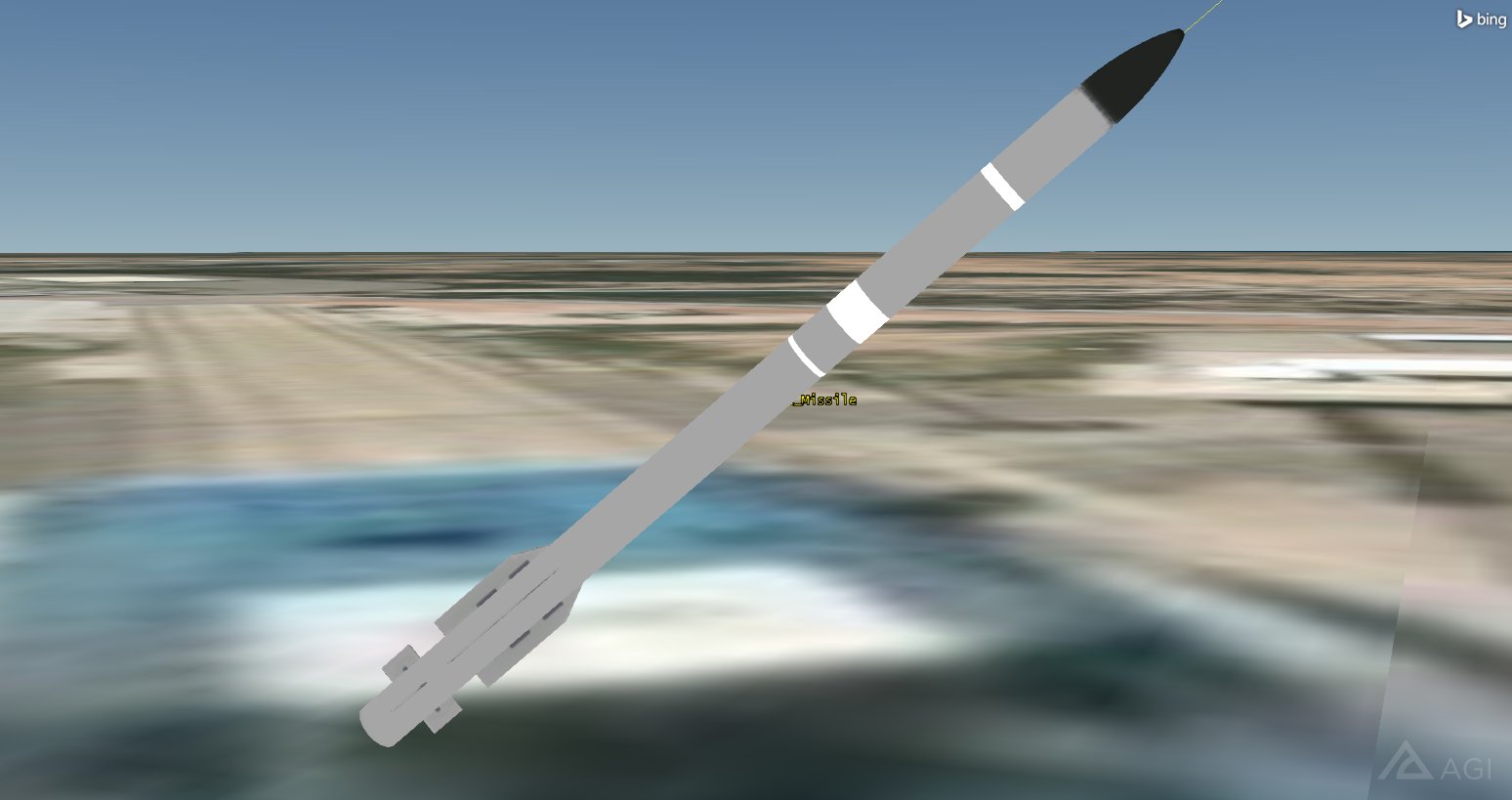
Test Missile on Launch Pad
How Long is the Missile's Flight Time
You can determine the missile's flight time and other pertinent information using the Report & Graph Manager. There are a few reports that will provide the flight time but each report will provide different data concerning the missile itself (e.g. Altitude vs Ground Range, Beta Angle, Ephemeris-IFT-LLA, etc.). To keep it simple, generate an Altitude vs Ground Range report.
- In the Object Browser, right click on Test_Missile () and select the Report & Graph Manager (
 ).
). - In the styles list, select and generate an Altitude vs Ground Range (
 ) report.
 - Scroll through the report.
- Note the time that Test_Missile () impacts in the test range.
- When finished, close the report and the Report & Graph Manager ().
Add a Transmitter to the Missile
Test_Missile () has a transmitter attached to it that will pass telemetry data to the ship.
- Using the Insert STK Objects Tool () insert a Transmitter (
 ) object using the Insert Default method.
 - In the Select Object window, select Test_Missile () and click OK.
- Rename the Transmitter () object "Missile_Tx".
Set the Transmitter Options
Use a Medium Transmitter Model.
- Open Missile_Tx's () Properties ().
- Select the Basic - Definition page.
- Set the following options:
- Click Apply.
| Option | Value |
|---|---|
| Type | Medium Transmitter Model |
| Frequency | 2.41 GHz |
| Power | 80 W (Watts) |
| Gain | -0.57 dB |
| Data Rate | 2.048 Mb/Sec |
This medium transmitter model defaults to an omnidirectional antenna with constant gain. An omnidirectional antenna radiates uniformly in all directions. A gain of zero (0) dB is representative of a theoretical perfect transmitter system.
Set the Modulation Type
Missile_Tx will use Bi-phase shift keying (BPSK). You will use the Power Spectral Density (PSD). PSD is used to determine the Bandwidth Overlap Factor. By using signal PSD, you combine the entire signal including losses in your analysis. The nulls are where the main lobe and side lobes drop to zero. If this option is not selected, the PSD will be modeled as a flat spectrum with unity magnitude across the transmitter’s bandwidth.
- Select the Modulator tab.
- Set the Modulator type to BPSK.
- Enable the Use Signal PSD option.
- Click OK.
Add a Sensor to the Ship
You need to add a Sensor ( ) object to the ship that will target Test_Missile (). It will act as the ship receiver's steering motor. The receiver will accept Missile_Tx's (
![]() ) telemetry transmissions.
) telemetry transmissions.
- Using the Insert STK Objects Tool () insert a Sensor () object using the Insert Default method.
- In the Select Object window, select Ship (
 ) and click OK.
 - Rename the Sensor () object "Tgt_Missile".
Define the Sensor's Cone Angle
The Sensor () object's field of view is not being used for anything other than situational awareness. In order to see it, but keep it from obstructing other views in the 3D Graphics window, minimize its half angle.
- Open Tgt_Missile’s () properties ().
- Select the Basic - Definition page.
- Set the Cone Half Angle to five (5) degrees.
- Click Apply.
Antenna Location
To add realism to your analysis by placing the antenna motor at its actual location on the ship.
- Select the Basic - Location page.
- Set the following options:
- Click Apply.
| Option | Value |
|---|---|
| Location Type: | Fixed |
| X: | 75 ft |
| Z: | 75 ft |
Target the Test Missile
Next, target the test missile.
- Select the Basic - Pointing page.
- Set the Pointing Type to Targeted.
- In the Available Targets list, move (
 ) Test_Missile () to the Assigned Targets list.
 - Click OK.
- Bring the 3D Graphics Window to the front.
- In the Object Browser, right click on Ship () and select Zoom To.
- Start () the animation. When Tgt_Missile () accesses Test_Missile (), the Sensor () object will be visible. Note its location.
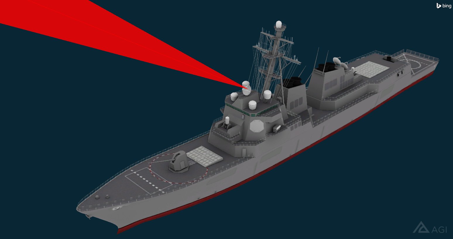
Sensor Targeting Test Missile
- When finished, reset () the scenario.
Add a Receiver to the Ship
Use a Receiver ( ) object to receive telemetry transmissions from the missile. Use a complex receiver model employing the Auto Track option.
- Using the Insert STK Objects Tool () insert a Receiver () object using the Insert Default method.
- In the Select Object window, select Tgt_Missile () and click OK.
- Rename the Receiver () object "Ship_Rx".
Define the Telemetry Receiver
Ship_Rx () is going to accept the telemetry data from Missile_Tx (![]() ).
).
- Open Ship_Rx's ()properties ().
- Select the Basic - Definition page.
- Set the following options:
- Click Apply.
| Option | Value |
|---|---|
| Type: | Complex Receiver Model |
| Auto Track | On (default) |
Set the Antenna Properties
The receiver uses a Helix Antenna Pattern.
- Select the Antenna tab.
- Set the following options:
- Click Apply.
| Option | Value |
|---|---|
| Type: | Helix |
| Diameter: | 0.9 m |
| Turn Spacing | 1 mm |
| Number of Turns | 3 |
Visualize the Antenna Pattern
You can visualize antenna patterns in STK.
- Select the 3D Graphics - Attributes page.
- Set the following options:
| Option | Value |
|---|---|
| Volume Graphics - Show Volume | On |
| Volume Graphics - Gain Scale (per dB) | 0.5 km |
| Pattern - Set Azimuth and elevation resolution together | On |
| Azimuth - Resolution | 1 deg |
Gain Coloring
There are two methods for specifying how colors will be added to show antenna gain. Use the Explicit Levels Method to define individual antenna gain levels.
- In the Gain Coloring field, set the following options.
- Set the following Level Adding options:
| Option | Value |
|---|---|
| Method | Explicit Levels |
| Relative to Maximum | On |
| Option | Value |
|---|---|
| Add Method | Start, Stop, Step |
| Relative to MaximumVolume Graphics - Gain Scale (per dB) | On |
| Start | -30 (dB) |
| Stop | 40 (dB) |
| Step | 10 (dB) |
- Click Add Levels.
- Click Apply.
- Bring the 3D Graphics Window to the front.
- In the Object Browser, right click on Ship () and select Zoom To.
- Start () the animation. When Tgt_Missile () accesses Test_Missile (), the antenna pattern will be visible. You may want to decrease () the Time Step and zoom out a bit.
- When finished, reset () the scenario.
- Return to Ship_Rx's ()properties ().
- Turn off Show Volume.
- Click OK.
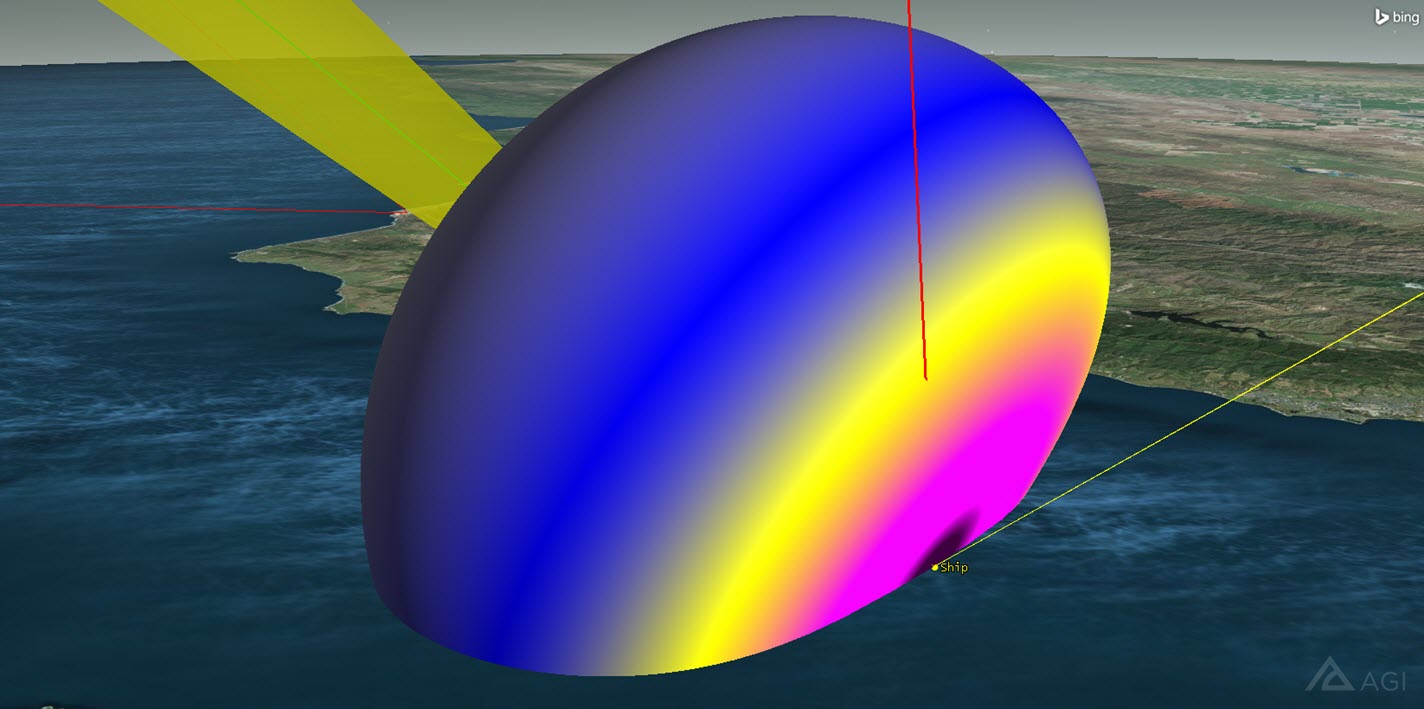
Helix Antenna Pattern
Analyze the Telemetry Downlink
The missile will transmit telemetry data to the ship during its flight. It’s important that nothing interferes with the downlink of the missile telemetry data. Let’s make sure a connection is available between the ship’s receiver and the missile’s transmitter. The link budget report gives you the signal strength and quality of the link received at the ship from the missile.
- Select Ship_Rx () in the Object Browser.
- Click the Access tool button (
 ) on the STK Tools toolbar.
 - In the Associated Objects List expand (
 ) the Object Tree under Test_Missile.
 - Select Missile_Tx ().
- Click the Link Budget report button.
- Scroll to the right until you find the column BER (Bit Error Rate).
- Scroll down through the column.
For the most part, you have good reception from the missile to the ship. As the test missile gets further from the ship, the Bit Error Rates increase. However, the link budget report doesn't take into account if there is interference affecting the ship's reception of the telemetry data due to the XM Satellite transmitters. For that, you need the CommSystem ( ) Object.
Clean up the Accesses
- Bring the Access tool to the front.
- Click the Remove All Access (
 ) button under the Access for: panel.
 - Close the Access () tool.
Create the Communications System
The Communications Module provides a CommSystem () object that allows you to model dynamically configured communications links between constellations of transmitters and receivers. The CommSystem () object lets you identify interference sources and calculate the impact of interference on the communications link.
To set up a CommSystem () object, you must first organize the relevant communications assets into three groups:
- the transmitter(s) in the communications link of interest
- the receiver(s) in the communications link of interest
- the potentially interfering transmitter(s)
This grouping is accomplished with the help of the Constellation ( ) object.
Transmitter Constellation
Place the missile transmitter into a single constellation.
- Using the Insert STK Objects Tool () insert a Constellation () object using the Define Properties method.
- Move () Missile_Tx () from the Available Objects list to the Assigned Objects list.
- Click OK.
- Rename the Constellation () object "Transmitter".
Receiver Constellation
Place the ship’s receiver into a single constellation.
- Using the Insert STK Objects Tool () insert a Constellation () object using the Define Properties method.
- Move () Ship_Rx () from the Available Objects list to the Assigned Objects list.
- Click OK.
- Rename the Constellation () object "Receiver".
Interference Constellation
The interference constellation will have the transmitters that are potentially interfering with the telemetry data.
- Using the Insert STK Objects Tool () insert a Constellation () object using the Define Properties method.
- Move () XM3_Tx (), XM4_Tx () and XM5_Tx () from the Available Objects list to the Assigned Objects list.
- Click OK.
- Rename the Constellation () object "Interference".
Configure the CommSystem Object
Using the constellations you just created, you can now build the CommSystem () object. Once you have the CommSystem () object configured, you can determine if the XM transmitters are interfering with the telemetry data being transmitted from the test missile to the ship.
If you don't have a CommSystem () object in the Insert STK Objects () tool, you can add it by performing the following steps:
- In the Insert STK Objects tool (), click the Edit Preferences... button.
- When the Preferences window opens, find the Define Default Creation Methods field.
- In the (Check the "Show" item to display the object in the "New Object" tool) field, locate and enable Comm System.
- Click OK.
- Use the Insert STK Objects Tool () to insert a Comm System () object using the Define Properties method.
- On the Basic - Transmit page, move () the Transmitter constellation () from the Available Constellation list to the Selected Constellation list.
- Browse to the Basic - Receive page.
- Move () the Receiver constellation () from the Available Constellation list to the Selected Constellation list.
- Browse to the Basic - Interference page.
- Move () the Interference constellation () from the Available Constellation list to the Selected Constellation list.
- Click OK.
Check for Interference
Compute the CommSystem () object to determine if the XM satellites will interfere with the telemetry data.
- Save (
 ) your scenario.
 - Select CommSystem1 () in the Object Browser.
- Open the CommSystem menu item in the STK menu area and select Compute Data.
- Return to the Object Browser, right click on CommSystem1 () and select Report & Graph Manager ().
- In the Styles list, ensure Show Reports is enabled.
- Select the Link Information Detailed report () and click the Generate... button.
- At the top of the report, click the Show Step Value button.
- Change Step: to 1 sec.
- Locate the BER and BER+I columns.
- BER+I is Bit Error Rate plus Interference.
- Scroll down through the report and compare both columns.
A progress bar will appear in the lower right corner of STK. When the progress bar reaches 100%, it will disappear. Your calculation is complete.
In this analysis, you require a BER of 1.0000e-09 or lower. You can see that the XM transmitters will interfere with the telemetry data being transmitted from the test missile to the ship. Note at what time interference raises the BER above 1.0000e-09 (e.g. 8 Jan 2018 16:00:25.000).
- Leave the report open.
- Close the Report & Graph Manager ().
Spectrum Filter
Having determined that the XM satellites will interfere with the ship's receiver, you can apply a spectrum filter.
Applying a spectrum filter reduces the effect of the interference on the communication link. Suppressing the XM satellites signal at the receiver, the telemetry link should perform better in the presence of the interference.
A spectrum filter can be used to accurately model the power transfer from a transmitter to a receiver or an interference source to a receiver. This can be handy when trying to model adjacent band interference or for evaluating link performance for a given specific power spectrum mask.
Adding a filter to a receiver will shape the received PSD by multiplying it by the selected receiver filter’s frequency response.
Butterworth Filter
You will use a Butterworth Filter because it has a flat passband and has a moderately steep roll off. The Butterworth Filter will also suppress anything that falls outside of the passband. Ideally, you would like to filter out any satellite interference under five (5) MHz. However, this could be adjusted if required.
- Open Ship_Rx’s () properties ().
- Select the Basic - Definition page.
- Select the Filter tab.
- Enable the Use option in the Filter Model section.
- Ensure Butterworth is selected.
- Set the Order: to a value of 4.
- Set the Cut-off Frequency: to a value of 5 MHz.
- Click OK.
Recompute the CommSystem Object Link Budget
You want to see the effect of filtering on your signal quality.
- Bring the Link Information report to the front.
- Refresh (
 or F5) the Report Data window.
 - At what time does the interference start to have an effect?
- By how much does the interference affect the signal?
Notice that BER with interference (using filtering) shows improvement in link performance over BER with interference (without filtering).
You will see approximately a 50 db of improvement in the Eb/(No + Io) with the Butterworth filter. With the Butterworth filter, the ship can receive the missile’s transmissions a few minutes longer. You could further tweak the values but this would be based on acceptable changes to your bandwidth.
When You Finish
- Close the Link Information Detailed report, and the Report & Graph Manager ().
- Save () your scenario.
 Visit AGI.com