STK Professional and Communications.
The results of the tutorial may vary depending on the user settings and data enabled (online operations, terrain server, dynamic Earth data, etc.). It is acceptable to have different results.
Create a Scenario
Start by creating a scenario.
- Create a scenario and name it Transponders.
- Change Start: to 1 Jul 2016 16:00:00.000 UTCG and Stop: to + 24 hrs.
Save Often!
Introduction
STK Communications, together with the Chain and Constellation objects, makes it easy to model analog and digital transponders.
You will use STK Communications to model a one‐hop, transcontinental communications link from Vandenberg Air Force Base (AFB) to Eglin Air Force Base via a transponder mounted on a geostationary (GEO) satellite. In this scenario, you are going to model both an Analog Transponder and a Digital Transponder.
Turn Off Terrain Server
Analytical Terrain is not required in this scenario.
- Open Transponder's properties.
- Browse to the Basic - Terrain page.
- Disable Use terrain server for analysis.
- Click OK.
Add Facilities
Start by inserting Vandenberg AFB and Eglin AFB.
- Using the Insert STK Objects tool, insert a Facility (
 ) object using the From Standard Object Database method.
 - Enter Vandenberg in the Name: option.
- Click Search.
- Select Vandenberg AFB in the Search Results field. The Source column should be Local Database.
- Click Insert.
- Return to Name: and enter Eglin.
- Click Search.
- Select Eglin AFB STDN EG3F. The Source column should be Local Database.
- Click Insert.
- Close the Insert Facility From Database window.
- Return to the Object Browser and rename your Facility objects Vandenberg and Eglin.
Add a Satellite
For the communications satellite, you'll use the Orbit Wizard to create a geosynchronous satellite.
- Using the Insert STK Objects tool, insert a Satellite (
 ) object using the Orbit Wizard method.
 - When the Orbit Wizard window appears, make the following changes:
- Click OK.
| Option | Value |
|---|---|
| Type: | Geosynchronous |
| Satellite | CommSat |
Servomotor
In STK, if you have an antenna that targets or tracks another object, you use a Sensor object as the servomotor. Start with Vandenberg.
- Using the Insert STK Objects tool, insert a Sensor (
 ) object using the Insert Default method.
 - When the Select Object window appears, select Vandenberg and then click OK.
- In the Object Browser, rename the Sensor object "ServoUL".
- Open ServoUL's () properties (
 ).
). - On the Basic - Definition page, in the Simple Conic field, change Cone Half Angle: to 2 deg. This is for situational awareness only.
- Browse to the Basic - Pointing page.
- Set the Pointing Type to Targeted.
- Move (
 ) CommSat from the Available Targets list to the Assigned Targets list using the right arrow.
 - Click OK.
Add a Servomotor to Eglin
Now you will add a servomotor to Eglin AFB. In this case, simply reuse the Sensor object which is attached to Vandenberg.
- In the Object Browser, select ServoUL () and click the Copy (
 ) button.
 - Select Eglin and click the Paste (
 ) button.
 - Rename the Sensor object "ServoDL".
Add Two Sensors to CommSat
You will require two separate Sensor objects on the satellite. One will target Vandenberg and the other Eglin.
- Using the Insert STK Objects tool, insert a Sensor () object using the Insert Default method.
- When the Select Object window appears, select CommSat () and then click OK.
- Add a second Sensor () object by repeating steps 1 and 2.
- Rename one of the Sensor objects TgtVandenberg.
- Rename the other Sensor object TgtEglin.
Target Eglin
- Open TgtEglin's () properties ().
- On the Basic - Definition page, in the Simple Conic field, change Cone Half Angle: to 2 deg.
- Browse to the Basic - Pointing page.
- Set the Pointing Type to Targeted.
- Move () Eglin from the Available Targets list to the Assigned Targets list using the right arrow.
- Click OK.
Target Vandenberg
- Open TgtVandenberg's () properties ().
- On the Basic - Definition page, in the Simple Conic field, change Cone Half Angle: to 2 deg.
- Browse to the Basic - Pointing page.
- Set the Pointing Type to Targeted.
- Move () Vandenberg from the Available Targets list to the Assigned Targets list using the right arrow.
- Click OK.
Define Communication Assets
Set up STK Transmitter and Receiver objects. These will be chained together in sequence to represent the behavior of a transponder. Start by adding a Transmitter object to Vandenberg. You will use the default antenna model for your Transmitter and Receiver objects. STK uses the Gaussian Antenna type.
- Using the Insert STK Objects tool, insert a Transmitter (
 ) object using the Insert Default method.
 - When the Select Object window appears, select ServoUL () and then click OK.
- In the Object Browser, rename the Transmitter object "ULXmtr".
- Open ULXmtr's () properties ().
- On the Basic - Definition page, make the following changes:
- Click OK.
| Option | Value |
|---|---|
| Type: | Complex Transmitter Model |
| Power: | 10 dBW |
Add a Receiver object to Eglin.
- Using the Insert STK Objects tool, insert a Receiver (
 ) object using the Insert Default method.
 - When the Select Object window appears, select ServoDL () and then click OK.
- In the Object Browser, rename the Receiver object "DLRcvr".
- Open DLRcvr's () properties ().
- On the Basic - Definition page, change Type: to Complex Receiver Model.
- Click OK.
Add a Receiver object to CommSat
- Using the Insert STK Objects tool, insert a Receiver () object using the Insert Default method.
- When the Select Object window appears, select TgtVandenberg () and then click OK.
- In the Object Browser, rename the Receiver object "ULRcvr".
- Open ULRcvr's () properties ().
- On the Basic - Definition page, change Type: to Complex Receiver Model.
- Click OK.
Add Two Transmitters to the TgtEglin Sensor that is attached to CommSat.
- Using the Insert STK Objects tool, insert a Transmitter () object using the Insert Default method.
- When the Select Object window appears, select TgtEglin () and then click OK.
- Add a second Transmitter object by repeating steps 1 and 2.
- In the Object Browser, rename one Transmitter object "AnalogXmtr" and the other one "DigitalXmtr".
- Open AnalogXmtr's () properties ().
- On the Basic - Definition page, make the following changes:
| Option | Value |
|---|---|
| Type: | Complex Re-Transmitter Model |
| Sat. Power: | 13 dBW |
| Sat. Flux Density: | -100 dBW/m^2 |
- Click OK.
- Open DigitalXmtr's () properties ().
- On the Basic Definition page, make the following changes:
- Click OK.
| Option | Value |
|---|---|
| Type: | Complex Transmitter Model |
| Frequency: | 13.8 GHz |
| Power: | 7 dBW |
Analog Transponder
![]()
Analog Transponder
STK Communications models an analog transponder as a combination of a receiver and a retransmitter. In an analog transponder, the transmitted signal is essentially a reflection of the received signal, with the added possibility of frequency translation or power amplification. Thus, a convenient way to model the link - a one‐hop link from Vandenberg to Eglin - is to construct a chain with constituent links from:
- ULXmtr to ULRcvr
- ULRcvr to AnalogXmtr
- AnalogXmtr to DLRcvr
- Using the Insert STK Objects tool, insert a Chain (
 ) object using the Insert Default method.
 - In the Object Browser, rename the Chain object "AnalogLink".
- Open AnalogLink's () properties ().
- In the Basic - Definition page select each item from the Available Objects list, then right‐arrow it over to the Assigned Objects list in the following sequence:
- ULXmtr
- ULRcvr
- AnalogXmtr
- DLRcvr
- Click OK.
Make certain that you select the specified transmitters and receivers (not their parent objects), and that you enter them in the specified order. You can see the communications link in the 2D Graphics window.
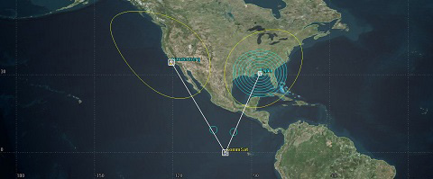
Comm Link
Bent Pipe Report
You can use the Report & Graph Manager to analyze the performance of your communication link.
- In the Object Browser, right click on AnalogLink () and select Report & Graph Manager.
- In the Styles list, expand Installed Styles.
- Select Bent Pipe Comm Link report and click the Generate button.
- Close the Bent Pipe Comm Link report and the Report & Graph Manager.
The report contains link performance data for the uplink (first line), downlink (second line), and the combined link (third line). Degradation in downlink and composite link performance can readily be perceived. For example, Bit Error Rate (BER) is 3.4 x 10‐23 in the uplink, 1.6 x 10‐4 in the downlink, and 3.6 x 10‐4 in the composite link.
Digital Transponder
![]()
Digital Transponder
In a digital (or regenerative) transponder, there is complete demodulation and re‐modulation of the incoming signal before it is sent on its way.
- Using the Insert STK Objects tool, insert a Chain () object using the Insert Default method.
- In the Object Browser, rename the Chain object "DigitalLink".
- Open DigitalLink's () properties ().
- In the Basic - Definition page select each item from the Available Objects list, then right‐arrow it over to the Assigned Objects list in the following sequence:
- ULXmtr
- ULRcvr
- DigitalXmtr
- DLRcvr
- Click OK.
Digital Repeater Comm Link Report
You can use the Report & Graph Manager to analyze the performance of your communication link.
- In the Object Browser, right click on DigitalLink and select Report & Graph Manager.
- In the Styles list, expand Installed Styles.
- Select Digital Repeater Comm Link and click the Generate button.
You'll see that for several elements of performance, such as BER, while there may be degradation in the downlink, no further degradation is noted in the composite link which can be seen in the BER Tot.2 column.
Comparative Link Quality
Display the Bent Pipe Comm Link and Digital Repeater Comm Link reports for the AnalogLink and DigitalLink Chains in such a way that you can view them simultaneously on the screen.
You will see immediately that uplink and downlink performance are substantially the same for the analog and digital links, but that composite link performance is significantly better for the digital transponder. This is due to, among other things, the fact that the noise in the uplink channel is propagated through the downlink by the analog transponder but not by the digital transponder.
Moreover, the analog transponder achieves the same downlink performance as the digital transponder only by using twice the power. If you review the properties you set for the DigitalXmtr Transmitter, you will see that the power setting is 7 dBW. If you increase the power of the DigitalXmtr Transmitter, you will see a dramatic upsurge in downlink and composite link performance for the digital transponder.
Try various settings for the transmitters and receivers in this telecommunications link and note their effect, if any, on uplink, downlink, and composite link performance for the two transponder models. Be sure to refresh the reports after each change you introduce.
 Visit AGI.com