Quadcopter Design and Performance Analysis over Terrain
STK Professional, Aviator, Aviator Pro, Coverage, Terrain Integrated Rough Earth Model (TIREM) and Communications
To obtain required product licenses and an installation of the TIREM extension, contact Support at 1-800-924-7244 / 610-981-8888 or Email at eval@agi.com. Throughout this tutorial, if user interface values are not mentioned, that implies that you should keep the default values. Only change the values as instructed.
The results of the tutorial may vary depending on the user settings and data enabled (online operations, terrain server, dynamic Earth data, etc.). It is acceptable to have different results.
This tutorial uses model files that are not in the 11.4 install or older. You can download them here. These are strictly for visualization. If you don't have the files, it does not affect the analysis portion of the exercise.
Watch the following video, then follow the steps below incorporating the systems and missions you work on (sample inputs provided).Problem Statement
Towers, buildings, bridges, and other structures require regular maintenance. Drones allow inspectors to perform a preliminary survey which is used to determine where and what work is required on the structure and if any hazards are present. In combat, drones can be sent to surveil an area prior to sending in troops. This tutorial can be used by either group on how to use STK to model a drone and its remote controller.
A remote communication tower sits on top of a large hill. There are no roads to the top of the hill, so inspectors want to use a drone that will fly to the communication tower, take video of the structure, and fly back to the inspectors. The drone can be preprogrammed to fly its mission. When applicable, inspectors would like to have manual control of the drone using a remote controller. Inspectors have a good idea of the location from which they would like to launch the drone but potential problems exist. Will the drone's battery last during the entire flight and can inspectors contact the drone using remote control? Furthermore, inspectors want to determine how well the remote controller will function inside a predetermined geographic area. Due to the size of the communication tower, guyed anchors and wires are a potential hazard, so inspectors want to fly at a safe distance from the communication tower while still obtaining good video inspection using the zoom function on the drone's camera. Based on the drone's configuration, the battery should last 28 minutes.
Solution
Build an STK scenario that simulates the performance of a commercial drone built to specifications. Launch the drone, ascent up the hill, make four passes to inspect the upper half of the communication tower, and return to the launch site. Determine if the drone's battery will last during the programmed portion of the flight. Build a remote controller to determine if inspectors can manually control the drone based on their location and local terrain.
Create a New Scenario
Create a new scenario with a run time of one (1) hour.
- Launch STK (
 ).
). - Click the Create a Scenario (
 ) button.
 - Enter the following in the New Scenario Wizard:
- When you finish, click OK.
- When the scenario loads, click Save (
 ). A folder with the same name as your scenario is created for you in the location specified above.
 - Verify the scenario name and location and click Save.
| Option | Value |
|---|---|
| Name: | AviatorPro_Drone |
| Start: | 1 Jan 2018 19:00:00.000 UTCG |
| Stop: | + 1 hr |
Save Often!
Disable STK Terrain Server
Since you'll use a local terrain file for analysis and visualization, turn off STK Terrain Server.
- Open AviatorPro_Drone's () properties (
 ).
). - Browse to the Basic – Terrain page.
- Disable Use terrain server for analysis.
- Click Apply.
Surface Lines
Due to disabling Terrain Server, you want to display any object's lines on the surface of the central body when terrain data is available.
- Select the 3D Graphics - Global Attributes page.
- In the Surface Lines field, change On Terrain: to On.
- Click Apply.
Set TIREM as the Propagation Loss Model
The TIREM (Terrain Integrated Rough Earth Model) extension allows STK Communications to predict radio frequency propagation loss over irregular terrain and seawater for ground-based and air-borne transmitters and receivers.
- Select the RF - Environment page.
- Click the Atmospheric Absorption tab.
- Enable Use.
- Select the TIREM model as the Model Type and click OK.
- Click OK to accept the changes to the scenario properties.
Enable a Local Terrain File
Add analytical and visual terrain from a local file. Microsoft Bing Maps can be used for imagery. However, imagery is not required.
- Bring the 3D Graphics window to the front.
- Click the Globe Manager (
 ) icon or click the View menu and select Globe Manager.
 - In the Globe Manager - Hierarchy Window, click the Add Terrain/Imagery (
 ) button.
 - Click the ellipsis (
 ) button and navigate to <STK install folder>\Data\Resources\stkTraining\imagery (e.g. C:\Program Files\AGI\STK 11\Data\Resources\stkTraining\imagery).
 - Select PtMugu_ChinaLake.pdtt and click Open.
- When prompted to Use Terrain for Analysis, click Yes.
Label Declutter
Use to separate the labels on objects that are in close proximity for better identification in small areas and on terrain.
- Open the 3D Graphics window's properties ().
- On the Basic - Details page, enable Label Declutter.
- Click OK.
Communication Area
Use an Area Target ( ) object to outline the area in which inspectors may need remote control access to the drone.
- Using the Insert STK Objects Tool (
 ) insert an Area Target () object using the Area Target Wizard () method.
 - In the Area Target Wizard, change Name: to "Comm_Area".
- Click Insert Point four (4) times and set the following:
- Click OK.
| Point | Latitude | Longitude |
|---|---|---|
| Point 1 | 35.44 deg | -117.5 deg |
| Point 2 | 35.44 deg | -117.4 deg |
| Point 3 | 35.34 deg | -117.4 deg |
| Point 4 | 35.34 deg | -117.5 deg |
Communication Tower
Use a Place ( ) object to simulate the communication tower.
- Using the Insert STK Objects Tool () insert a Place () object using the Define Properties () method.
- On the Basic - Position page, set the following:
- Click Apply.
| Option | Value |
|---|---|
| Latitude: | 35.393 deg |
| Longitude: | -117.4386 deg |
Add a Realistic Model
The communication tower model is a generic model file, let's change it to be something more realistic.
- Select the 3D Graphics - Model page.
- In the Model field enable Show.
- Click the Model File: ellipses () button and navigate to <STK install folder>\Data\Data\stkTraining\samples (e.g. C:\Program Files\AGI\STK 11\Data\Data\stkTraining\samples).
- Select comm_tower.mdl and click Open.
- In the Detail Thresholds field, move the All slider to the right.
- Click OK.
- Rename the Place () object "Comm_Tower."
Technicians Location
The technicians will drive a ground vehicle to the location of the drone launch. This location is where they are interested in testing the remote controller.
- Using the Insert STK Objects Tool () insert a Ground Vehicle (
 ) object using the Define Properties () method.
 - On the Basic - Route page, set Route Calculation Method: to Specify Time.
- In the Altitude Reference field, set Interp Method: to Terrain Height.
- Click the Insert Point button and set the following:
- Click the Insert Point button.
- On the second waypoint, add one hour to the time.
- Click OK.
- Name the Ground Vehicle () object "Technicians."
| Option | Value |
|---|---|
| Latitude: | 35.4122 deg |
| Longitude: | -117.4634 deg |
| Altitude: | 1 m |
Quadcopter Drone
You will build a quadcopter drone using specifications from a popular model used to survey towers. Aviator Pro allows you to model the performance characteristics of rotorcraft as a distinct type of aircraft from a fixed wing aircraft. You can create a rotorcraft model in the User Rotorcraft Models catalog of the Aviator catalog interface or catalog manager. The buttons on the Initial Aircraft Setup toolbar are used to define the aircraft model that will be used in the mission.
- Using the Insert STK Objects Tool () insert an Aircraft (
 ) object using the Insert Default () method.
 - Rename the Aircraft () object "Drone."
- Open Drone's () properties ().
- Set the Propagator: to Aviator.
- On the Initial Aircraft Setup toolbar, click the Select Aircraft (
 ) icon.
 - Right click on User Rotorcraft Models.
- Select New Item.
- Rename New Rotorcraft "QuadcopterPM" (PM stands for Performance Model).
- Click OK.
- Click Apply.
Flight Path Warning
Aviator performs best in the 3D Graphics window when the surface reference of the globe is set to Mean Sea Level. You will receive a warning message when you apply changes or click OK to close the properties window of an Aviator object with the surface reference set to WGS84. It is highly recommended that you set the surface reference as indicated before working with Aviator.
- When the Flight Path Warning window opens, click the Optimize for Aviator button.
- Click OK.
Aircraft Properties
You are building a lightweight drone which is carrying a battery and a camera. The battery and camera are added as payload to the drone. Flight characteristics need to be built to specifications. These can be changed in the Aircraft object's properties.
- Click the Aircraft Properties (
 ) icon.
 - In the Performance Models tab, set the following:
- Click Save.
- Select the Aero/Propulsion tab, set the following Aerodynamics properties:
- Set the following Power Plant options:
- Click the 3D Model File ellipses () button and navigate to <STK install folder>\Data\Data\stkTraining\samples (e.g. C:\Program Files\AGI\STK 11\Data\Data\stkTraining\samples).
- Select the md4-200.mdl file and click Open.
- Click Save.
- Click Close.
- Click Apply.
| Option | Value |
|---|---|
| Max Altitude: | 10000 ft |
| Default Cruise Altitude: | 100 ft |
| Descent Rate Factor: | 50 % |
| Max Climb Angle: | 60 deg |
| Max Decent Angle: | 60 deg |
| Min Descent Rate: | 1000 ft/min |
| Max Load Factor G: | 1.05 G-SeaLevel |
| Roll Rate: | 400 deg/sec |
| AOA Pitch Rate: | 60 deg/sec |
| Sideslip/Yaw Rate: | 30 deg/sec |
| Max Transition Pitch Angle: | 50 deg |
| Max Safe Airspeed | 31 nm/hr EAS |
| Max Safe Translation Speed | 15 nm/hr EAS |
| Option | Value |
|---|---|
| Rotor Count: | 4 |
| Rotor Diameter: | 9.4 in |
| Blades per Rotor | 2 |
| Blade Chord: | 1 cm |
| Fuselage Flat Plate Area: | 0.01 m^2 |
| Blade Profile Drag K: | .01 |
| Induced Power Correction Factor: | 1 |
| Option | Value |
|---|---|
| Type: | Electric |
| Max S/L Power: | 1400 Watt |
Aircraft Configuration
The drone's empty weight is actually its full weight. In this case, your saying that the weight of the drone includes the battery, propellers and the camera.
- On the Initial Aircraft Setup toolbar, select the Configuration (
 ) icon.
 - Select the Stations tab.
- Select Internal Fuel and click the Delete button.
- Select the Basic tab.
- Set both the Empty Weight: and Max Landing Weight: to 1.5 lb.
- Click OK.
- Apply your changes.
Mission Window
The Mission window is used to define the aircraft's route when Aviator has been selected as the propagator.
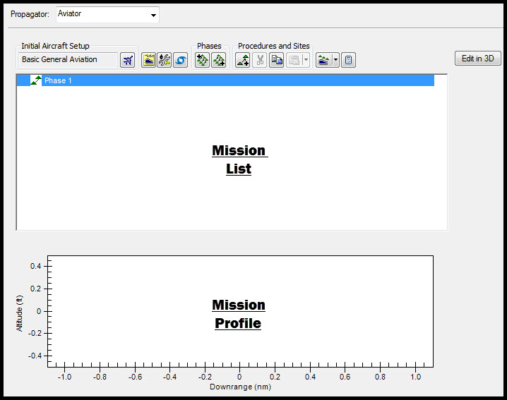
Mission Window
Take Off Procedure
Inspectors will launch the drone in a remote desert area at the base of the hill on which the communication tower is located.
- In the Mission List, right-click on Phase 1 and select Insert First Procedure for Phase (
 ).
). - In the Select Site list, select VTOL Point and set the following:
- Click the Add To Catalog button and then OK to close the Add Successful window.
- Click Next.
- In the Select Procedure Type list, select Vertical Takeoff (
 ) and set the following:
 - Click Finish.
- Click Apply.
- Bring the 3D Graphics window to the front.
- In the Object Browser, right-click on Drone and select Zoom To.
| Option | Value |
|---|---|
| Name: | VTOL Drone |
| Latitude: | 35.4121 deg |
| Longitude: | -117.4634 deg |
| Altitude: | 0 ft / AGL (height above ground level ) |
| Option | Value |
|---|---|
| Altitude offset: | 1.5 ft |
| Heading: | 133 deg / True |
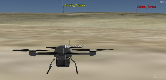
Drone at VTOL Point
Transition to Forward Flight
A Transition to Forward Flight procedure brings an aircraft from hover mode to forward flight mode.
- Return to Drone's () properties ().
- In the Mission List, right-click on Vertical Takeoff and select Insert Procedure After ().
- In the Select Site list, select End of Previous Procedure (
 ).
). - Click Next.
- In the Select Procedure Type field, select Transition to Forward Flight (
 ).
). - In the Transition Course field, enable Absolute: and set the value to 133 deg True.
- Click Finish.
- Click Apply.
Relative to Stationary STK Object
A Relative to Stationary STK Object site is a waypoint defined in relation to another, stationary, object in the current scenario.
- In the Mission List, right-click on Transition to Forward Flight and select Insert Procedure After ().
- In the Select Site list, select Relative to stationary STK Object (
 ) and set the following:
 - Click Next.
| Option | Value |
|---|---|
| Name: | Relative to Comm Tower |
| Link To Stationary STK Object: | Comm_Tower |
| Bearing: | 294 deg (True) |
| Range: | 300 ft |
Basic Point to Point
A Basic Point to Point procedure is a basic traverse between two waypoints.
- In the Select Procedure Type field, select Basic Point to Point (
 ) and set the following:
 - Change Enroute Cruise Airspeed to Max Endurance Airspeed.
- Click Finish.
- Click Apply.
| Option | Value |
|---|---|
| Name: | Arrive at Tower |
| Use Aircraft Default Cruise Altitude | off |
| MSL | 4400 ft |
First Pass
An STK Object Waypoint is used to define a waypoint at or relative to the position of another object within the scenario at a specific time. Move closer to the tower and fly a circular pattern around the top of the tower.
- In the Mission List, right-click on Relative to Comm Tower and select Insert Procedure After ().
- In the Select Site field, select STK Object Waypoint (
 ) and set the following:
 - Click Next.
| Option | Value |
|---|---|
| Name: | Comm Tower Pass 1 |
| Link To: | Comm_Tower |
| Offset Mode: | Bearing/Range (relative to North) |
| Bearing: | 180 deg (True) |
| Range: | 200 ft |
Holding Circular
You want to move the drone around the tower in a circular fashion. A circular holding procedure is how you can accomplish this.
- In the Select Procedure Type field, select Holding - Circular and set the following in the order shown:
- Click Finish.
| Option | Value |
|---|---|
| Name: | Holding - 4400 ft |
| Use Aircraft Default Cruise Altitude | Off |
| MSL Altitude: | 4400 ft |
| Hold Cruise Airspeed | Minimum Airspeed |
| Enroute Cruise Airspeed: | Minimum Airspeed |
| Bearing: | 305 deg |
| Range: | 150 ft |
| Diameter: | 300 ft |
| Use Alternate Entry Points: | off |
| Number of Full Turns: | 1 |
Second Pass
Reuse the last procedure.
- In the Mission List, right-click on Comm Tower Pass 1 and extend the Copy, Paste, Edit menu.
- Select the Copy Procedures option.
- Right-click on Comm Tower Pass 1 and extend the Copy, Paste, Edit menu.
- Select the Paste Procedures After option.
- Double-click on the new Comm Tower Pass 1 to open the STK Object Waypoint Properties window.
- Change Name: to Comm Tower Pass 2 and click OK.
- Double-click on the new Holding - 4400ft and set the following:
- Click OK.
| Option | Value |
|---|---|
| Name: | Holding - 4375 ft |
| MSL Altitude: | 4375 ft |
| Use Alternate Entry Points: | on |
Third Pass
Reuse the last procedure.
- In the Mission List, right-click on Comm Tower Pass 2 and extend the Copy, Paste, Edit menu.
- Select the Copy Procedures option.
- Right-click on Comm Tower Pass 2 and extend the Copy, Paste, Edit menu.
- Select the Paste Procedures After option.
- Double-click on the new Comm Tower Pass 2 to open the STK Object Waypoint Properties window.
- Change Name: to Comm Tower Pass 3 and click OK.
- Double click on the new Holding - 4375 ft and set the following:
- Click OK.
| Option | Value |
|---|---|
| Name: | Holding - 4350 ft |
| MSL Altitude: | 4350 ft |
| Hold Options / Profile Mode: | Allow climb/descent on station |
| Number of Full Turns: | 2 |
Fourth Pass
Reuse the last procedure.
- In the Mission List, right-click on Comm Tower Pass 3 and extend the Copy, Paste, Edit menu.
- Select the Copy Procedures option.
- Right-click on Comm Tower Pass 3 and extend the Copy, Paste, Edit menu.
- Select the Paste Procedures After option.
- Double-click on the new to open the STK Object Waypoint Properties window.
- Change Name: to Comm Tower Pass 4 and click OK.
- Double click on the new Holding - 4350 ft and set the following:
- Click OK.
| Option | Value |
|---|---|
| Name: | Holding - 4325 ft |
| MSL Altitude: | 4325 ft |
Head Away from the Tower
Fly away from the tower to avoid guyed wires.
- In the Mission List, right-click on Comm Tower Pass 4 and select Insert Procedure After ().
- In the Select Site list, select End of Previous Procedure ().
- Click Next.
- In the Select Procedure Type field, select Basic Maneuver (
 ) and set the following:
 - Enable the Downrange option.
- In the Basic Stop Conditions, set the following in the order shown:
- Click Finish.
| Option | Value |
|---|---|
| Name: | Straight Ahead 300 ft |
| Strategy: | Straight Ahead |
| Option | Value |
|---|---|
| Downrange: | 300 ft |
| Fuel State: | off |
We don't burn any fuel because it is an electric battery.
Return to the Technicians
The drone will turn 180 degrees and return to the VTOL point.
- In the Mission List, right-click on Straight Ahead 300 ft and select Insert Procedure After ().
- In the Select Site list, select End of Previous Procedure ().
- Click Next.
- In the Select Procedure Type field, select Basic Maneuver () and set the following:
- Enable the Downrange option.
- Set the following Basic Stop Conditions in the order shown.
- Click Finish.
- Click Finish again if required.
| Option | Value |
|---|---|
| Name: | Turn 180 deg |
| Strategy: | Simple Turn |
| Relative Turn Angle: | 180 deg |
| Option | Value |
|---|---|
| Down Range: | 600 ft |
| Fuel State: | off |
Transition to Hover
When the drone returns to the VTOL point, it will transition into a hovering maneuver and then land.
- In the Mission List, right-click on Turn 180 deg and select Insert Procedure After ().
- In the Select Site list, select VTOL Point from Catalog (
 ).
). - Locate and select VTOL Drone.
- Click Next.
- In the Select Procedure Type field, select Transition to Hover.
- In the Altitude field, set the following:
- Click Finish.
| Option | Value |
|---|---|
| AGL: | on |
| Altitude: | 10 ft |
Land
The drone lands at the same spot it took off.
- In the Mission List, right-click on Transition to Hover and select Insert Procedure After ().
- In the Select Site list, select VTOL Point from Catalog ().
- Locate and select VTOL Drone.
- Click Next.
- In the Select Procedure Type field, select Vertical Landing (
 ) and set the following:
 - Click Finish.
- Click Apply.
| Option | Value |
|---|---|
| Altitude Above Point: | 10 ft |
| Altitude Offset | 1.5 ft |
View the Flight Path
- Bring the 3D Graphics window to the front.
- Reset (
 ) the scenario.
 - Zoom To Drone.
- Play (
 ) the animation. As the drone flies to the communication tower, note the realistic flight characteristics.
 - When the drone is near the communication tower, pause (
 ) the scenario and notice the detail of the inspection paths.
 - When finished, return and land.
- Reset () the scenario
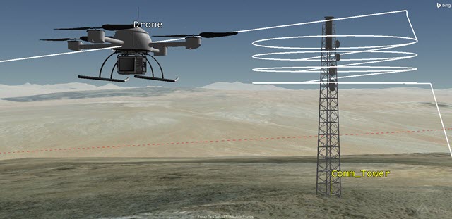
Inspection Paths
Custom Report
Create a custom report that shows the length of the mission and the amount of power drained from the drone's battery. Place the dynamic report on the 3D Graphics window. Based on the drone configuration, you have approximately twenty eight (28) minutes of battery life. You require a buffer of two minutes.
- In the Object Browser, right-click on Drone () and select the Report & Graph Manager (
 ).
). - In the Installed Styles list on the right, right-click on the Flight Profile by Time report.
- Select Properties ().
- In the Report Contents field, select Flight Profile By Time-Fuel Consumed.
- Click the Remove button. Since you're not burning fuel, this is not needed in the report.
- In the Report Contents field, ensure Flight Profile By Time-Ground Speed is selected.
- In the Data Providers list on the left, expand Flight Profile By Time if required.
- Select Energy Consumed. You may need to scroll through the list to find it.
- Move (
 ) Energy Consumed to the Report Contents field.
Change the Units
- Click Units.
- Disable the Use Defaults option.
- In the New Unit Value list, select watt-seconds (Ws).
- Click OK.
- Click OK. The warning is telling you that the original Flight Profile by Time report is locked out and that your new report is being saved in the My Styles folder.
- Click OK to dismiss the warning.
Generate the Report
- In the Styles list, expand the My Styles folder.
- Rename the report "My Flight Profile by Time."
- Generate the report.
- Close the Report & Graph Manager ().
Dynamic Display
Place the custom report onto the 3D Graphics window.
- Return to Drone's () properties ().
- Select the 3D Graphics - Data Display page.
- Click the Add... button.
- In the Add a Data Display window, select My Flight Profile by Time and click OK.
- Make any desired changes to Position and / or Appearance and click OK.
View in 3D
- Bring the 3D Graphics window to the front.
- Zoom To Drone ().
- Reset () the scenario, adjust the Step Size (
 ,
, ) as required, and click Start ().
 - When the drone lands, how much time elapsed from take off to landing?
- With an estimated battery life of 28 minutes minus the two (2) minute buffer, can you complete the mission?
- When finished, Reset () the scenario.
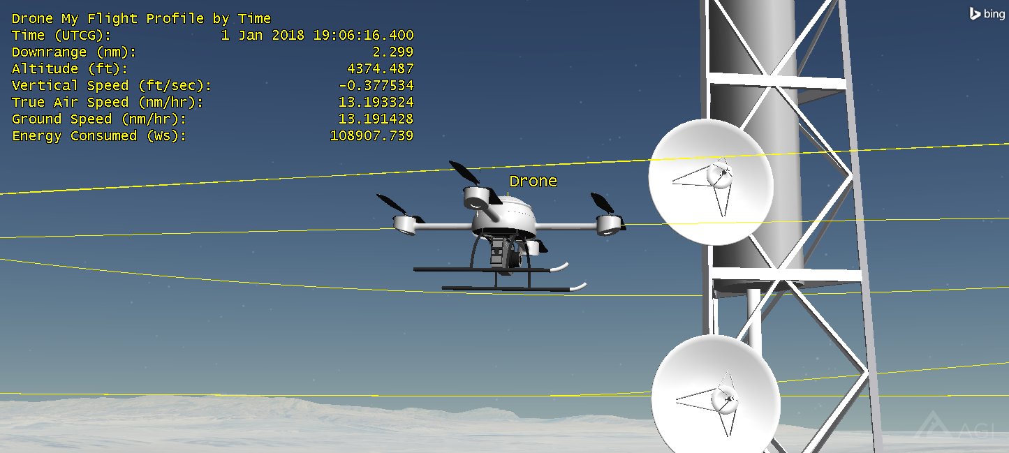
Dynamic Display
As the scenario plays, you can see the report dynamically display on the 3D Graphics window.
Disable the Data Display
- Open Drone's () properties ().
- Select the 3D Graphics - Data Display page.
- Turn off My Flight Profile by Time / Show.
- Click OK.
Remote Controller
There are two requirements that need to be met. You need to determine if the remote controller has constant contact with the drone during the mission, and should the drone malfunction, where will you loose control inside the designated communication area (Comm_Area). The manufacturer provides a certain amount of remote control specifications but not a lot. Therefore, you will use simple transmitter and receiver models for the preliminary analysis of the communications.
- Using the Insert STK Objects Tool, insert a Transmitter (
 ) object using the Define Properties () method.
 - When the Select Object window appears, select Technicians () in the list and click OK.
- On the Basic - Definition page, set the following:
- Click Apply.
- Select the Constraints - Basic page.
- Disable Line of Sight.
- Click OK.
- Rename the Transmitter () object "Tech_Tx."
| Option | Value |
|---|---|
| Frequency: | 2.4 GHz |
| EIRP: | 26 dBm (decibel-milliwatts) |
Disable Line-of-sight, Terrain Mask, or Az-El Mask constraints to take advantage of the over-the-horizon analysis capabilities of the TIREM module.
Drone Receiver
The manufacturer doesn't provide any specifications for the drone's receiver, so the only thing to do is set it up to use TIREM.
- Using the Insert STK Objects Tool, insert a Receiver (
 ) object using the Define Properties () method.
 - When the Select Object window appears, select Drone () in the list and click OK.
- Select the Constraints - Basic page
- Disable Line of Sight.
- Click OK.
- Rename the Receiver () object "Drone_Rx."
Link Budget
A simple link budget reports the values that determine the drone receiver's reception. For the purposes of this scenario, you will focus on Eb/No (energy per bit to noise power spectral density ratio). The minimum Eb/No requirement is five (5) dB.
- In the Object Browser, right-click on Drone_Rx.
- Select Access (
 ).
). - In the Associated Objects list, expand (
 ) Technicians () and select Tech_Tx ().
 - Click the Link Budget... button in the Reports area.
- When the link budget report appears, browse to the Eb/No (dB) column.
- How is the reception between Technicians and the drone?
- Close the link budget report and the Access tool.
- Extend the Analysis menu and select the Remove All Accesses option.
Coverage Analysis
The simple link budget analysis was very good. Basically, the line of sight between the technicians and the drone was never broken, so terrain wasn't much of a factor. However, should the drone's programming malfunction, terrain could become a communications issue. You want to keep the drone above 100 feet AGL at all times for this analysis.
- Using the Insert STK Objects Tool, insert a Coverage Definition (
 ) object using the Insert Default () method.
 - Rename the Coverage Definition () object “Tx_Coverage."
- Open Tx_Coverage’s () properties ().
- On the Basic – Grid page, change Grid Area of Interest Type: to Custom Regions.
- Click the Select Regions button.
- Move Comm_Area to the Selected Regions field.
- Click OK.
Set the Point Granularity
You are analyzing a smaller area that requires a smaller point granularity. You also should assign assets so that the receiver properties are applied to each point in the grid.
- In the Grid Definition field, change Point Granularity to Distance: and set the value to 0.25 km.
- Click Apply.
- Click the Grid Constraint Options... button.
- Set the Reference Constraint Class: to Receiver.
- In the Use Object Instance field, select Drone/Drone_Rx.
- Click OK.
- Change Point Altitude to Altitude above Terrain and set the value to 100 ft.
- Click Apply.
Assets
- Select the Basic - Assets page.
- In the Assets list, select Tech_Tx and click the Assign button.
- Click Assign.
Interval
Change the interval to compute for one second.
- Select the Basic - Interval page.
- In the Access Interval field, open the pull down menu and select Replace With Times.
- Change Stop: to +1sec.
- Click OK.
Compute Coverage
You've enclosed most of the hill with an Area Target object (Comm_Area). Grid points are laid out every 0.25 kilometer. The grid has been raised 100 feet off the ground. When you selected the Receiver object as the grid constraint, you basically placed the receiver at each point in the grid. Selecting the Transmitter object as the asset, you will compute coverage between the transmitter and the receiver at each point in the grid.
- In the Object Browser, right-click on Tx_Coverage.
- Expand the CoverageDefinition menu.
- Click Compute Accesses.
Analyze Coverage
Use a Coverage Figure of Merit object to analyze coverage.
- Using the Insert STK Objects Tool, insert a Figure Of Merit (
 ) object using the Insert Default () method.
 - When the Select Object window appears, select Tx_Coverage () and click OK.
- Rename the Figure Of Merit () object “CovAt_100FT."
- Open CovAt_100FT's () Properties ().
- On the Basic - Definition page, set the following:
- Click Apply.
| Option | Value |
|---|---|
| Type: | Access Constraint |
| Constraints: | Eb/No |
| Across Assets: | Maximum |
| Compute: | Maximum |
Grid Stats
The Grid Stats report summarizes the minimum, maximum and average static value for the Figure Of Merit over the entire grid.
- In the Object Browser, right-click on CovAt_100FT ().
- Select the Report & Graph Manager ().
- Generate the Grid Stats report.
- Scroll to the bottom of the report and note the Minimum (dB) and Maximum (dB) values.
You will use the values from the report to create color contours on the 3D Graphics window which will show you areas inside the Comm_Area () in which you will have and not have control of the drone.
Create Contours
You can specify how levels of coverage quality display in both the 2D and 3D Graphics windows by showing contours. To accurately display contour levels for figures of merit in the 2D and 3D Graphics window, you should know the approximate range of values for the current Figure Of Merit. These were obtained using the Grid Stats report.
- Return to CovAt_100FT's () properties ().
- Select the 2D Graphics - Static page.
- Change Filled Area - % Translucency to 25.
- Enable Show Contours and set the following Level Adding values:
- Click the Add Levels button.
- Ensure the Color Method is set to Color Ramp and set the following:
- In the Color Interpolation (points must be filled) field, enable Natural Neighbor Sampling.
- Click Apply.
| Option | Value |
|---|---|
| Start: | 5 dB (this is the lowest acceptable value) |
| Stop: | 85 dB (round down or use the actual maximum value from the Grid Stats report) |
| Step: | 5 dB |
| Option | Value |
|---|---|
| Start Color: | red |
| End Color: | blue |
Imbed a 3D Graphics Window Legend
The Legend provides you with a convenient way to interpret contour data displayed in the 2D and 3D Graphics windows.
- Click the Legend... button.
- When the Legend appears, click the Layout... button.
- In the 3D Graphics Window field, enable Show at Pixel Location.
- In the Text Options field, set the following:
- In the Range Color Options field, set Color Square Width (pixels) to 50.
- Bring the 3D Graphics window to the front.
- In the 3D Graphics window tool bar, click the Orient North button.
- Set the view so that you can see the Comm_Area and have some space above it to place the legend.
- Click the upper left hand corner of the 3D Graphics window.
- Click OK to close the Layout window.
- Close the floating Legend window.
- When finished, close Cov_100ft's () properties ().
| Option | Value |
|---|---|
| Title: | Eb/No dB |
| Number Of Decimal Digits: | 0 |
Wherever you click on the map, that's where the upper left hand corner of the legend will be placed. If the legend will resize, it will spread to the right.
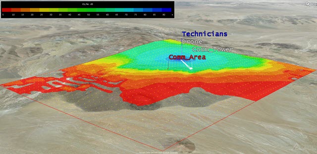
Coverage
Areas with color are areas that meet the requirement of an Eb/No of five (5) dB or higher. Areas without color are areas that you'll most likely lose communication to the drone from the controller if it's at an altitude of 100 feet. The lower the drone flies, coverage will most likely decline. Looking at the 3D Graphic window from the back of the hill with the technicians on the other side, you get an excellent example of TIREM in action. On your own, you can set different altitudes for the Coverage Definition () object and recalculate the results.
The FAA sets rules on how high a drone can fly. For the purposes of this scenario, we kept the altitude below 400 ft AGL. For further information concerning Small Unmanned Aircraft Regulations, you can visit the FAA Website.
Save Your Work
- When finished, close all reports.
- Close the Report & Graph Manager ().
- Save () your work.