STK Pro, STK Premium (Air), STK Premium (Space), or STK Enterprise
You can obtain the necessary licenses for this training by contacting AGI Support at support@agi.com or 1-800-924-7244.
The results of the tutorial may vary depending on the user settings and data enabled (online operations, terrain server, dynamic Earth data, etc.). It is acceptable to have different results.
Capabilities covered
This lesson covers the following STK Capabilities:
- STK Pro
Problem statement
Engineers and operators require a quick and simple way to simulate multi-hop relays of information (e.g. communications, images, data) between satellites and ground sites. With the increased global seismic activity, Italian intelligence wants you to collect visual imagery on one of the greatest tourist attractions; the Roman Colosseum. They want you to monitor the geography of the area around the Colosseum and its structural integrity.
To do this, you must take as many pictures of the Colosseum as possible and return them to White Sands or Guam within the next three weeks.
Solution
With STK, you can build a STK Scenario to determine when you can take near-real-time images of the Colosseum in daylight over the next three weeks. You will use the cameras attached to Landsat 7 or Landsat 8 satellites. After you take the images, you will uplink to a selected TDRS satellite and then downlink to a White Sands or Guam ground site.
What you will learn
Upon completion of this tutorial, you will have an understanding of the following:
- Chain objects
- Constellation objects
- Complete Chain Access Reports
- Individual Strand Access Reports
Video guidance
Watch the following video. Then follow the steps below, which incorporate the systems and missions you work on (sample inputs provided).
Creating a new scenario
You must start by creating a new STK scenario:
- Launch STK (
 ).
).
- Click in the Welcome to STK window.
- Enter the following in the STK: New Scenario Wizard:
- Click after you enter the scenario information.
- Click Save (
 ) once the scenario loads. You will create a folder with the same name as your scenario in the location specified above.
 - Verify the scenario name and location.
- Click .
- Close the Insert STK Objects window if it appears on start up.
| Option | Value |
|---|---|
| Name | Image_Relay |
| Description | How can I take pictures of the Colosseum and relay them in near-real-time? |
| Location | C:\Users\<username>\Documents\STK 12\ |
| Start | 1 Jul 2016 16:00:00.000 UTCG |
| Stop | + 21 days |
Turn off Terrain Server
The Terrain Server adds geographic features to the 3D Graphics Window that you do not need for this scenario's calculations.
- Right-click on Image_Relay (
 ) in the Object Browser.
 - Select Properties (
 ).
). - Select the Basic - Terrain page.
- Turn off Use terrain server for analysis.
- Click .
Globe Manager - KML window
You can use the KML window to add Keyhole Markup Language (KML) files (.kml/.kmz) to a 3D Graphics window. This enhances the visuals in the 3D Graphics window for movie making, briefings and situational awareness. Use a local *.kmz file to visualize the Roman Colosseum in the 3D Graphics window.
- Click Window in the upper ribbon.
- Click Tile Vertically in the Window drop down.
- Launch the Globe Manager (
 ) from within the 3D Graphics window.
 - Select the KML tab in the Globe Manager side bar.
- Click Open KML Content (
 ).
). - Browse to the location of your KML file. The default location is <STK install folder>\Data\Resources\stktraining\KML.
- Select romecolosseum.kmz.
- Click .
- Click Save ().
View the Roman Colosseum in the 3D Graphics Window
Once loaded, you can view the KML model in the 3D Graphics window.
- Right-click on model (
 ) in the KML browser.
 - Select Zoom To (
 ).
). - Close the informational dialog. The message informs you that the model was created using Google Sketchup.
- Mouse around in the 3D Graphics window until you can clearly see the Roman Colosseum. You may need to left-click then drag to pan around the Colosseum or you may need to scroll out with the mouse wheel to zoom out.
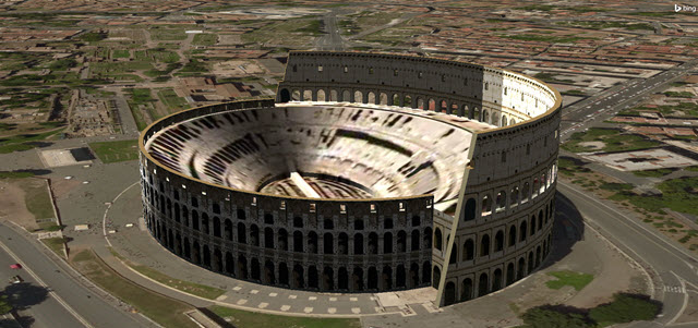
3D Graphics View of the Roman Colosseum
Promote the KML Model to an STK Object
You can use the Colosseum model for analysis in STK by promoting it into an STK object. Since the Colosseum is the target of your imaging satellites, promote it to an STK target object.
- Return to the Globe Manager.
- Expand (
 ) the model directory.
 - Right-click the Model (
 ) option.
 - Select the Import as Target option from the menu. You should see a new Target (
 ) object appear in the Object Browser.
 - Right-click on Model (
 ) in he Object Browser.
 - Select Rename.
- Rename the new Target () object "Colosseum."
View in 2D Graphics Window
- Bring the 2D Graphics window to the front.
- Left-click and drag with the Zoom In (
 ) tool on 2D Graphics window until you can clearly see the Colosseum.
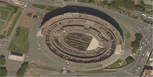
2D Graphics View of the Roman Colosseum
Model ground sites
You’ll use the information in the Facility Database to model selected U.S. Tracking and Data Relay Satellite System (TDRSS) ground sites. Specifically, you will add the White Sands and Guam Remote Ground Terminals to the scenario.
Insert a White Sands Ground Terminal.
- Click Insert Object (
 ).
). - Insert a Facility (
 ) object with the From Standard Object Database method.
 - Enter WSGT in the Name: field when the Search Standard Object Data window opens.
- Click .
- Select the Facility Name White Sands STDN WH3K from the Results list. You must have your Data Source as the AGI's Standard Object Data Service.
- Click . You should see a new Facility () object in the Object Browser named White_Sands_STDN_WH3K.
Insert a Guam Remote Ground Terminal
- Return to the Search Standard Object Data window.
- Enter Guam in the Name: field.
- Click .
- Select the Facility Name GRGT STDN GWMJ from the Results list. You must have your Data Source as the AGI's Standard Object Data Service.
- Click . You should see a new Facility () object in the Object Browser named GRGT_STDN_GWMJ.
- Close the Search Standard Object Data window when finished.
Group the TDRSS ground sites
In your scenario, you have the two ground stations used by the TDRSS network. You can group them together with a Constellation object. You want either of these facilities to collect the data whenever either one can complete the chain.
- Insert a Constellation (
 ) object using the Insert Default method.
 - Right-click on Constellation1 () in the Object Browser.
- Select Rename.
- Rename Constellation1 () to "TDRSS_Ground".
- Right-click on TDRSS_Ground (
 ).
). - Select Properties ().
- Select the Basic - Definition page when TDRSS_Ground's () properties open.
- Enable Facility () in the Selection filter.
- Move (
 ) the Facility () objects from the Available Objects list to the Assigned Objects list.
 - Click .
Landsat satellites
You can take pictures of the Colosseum with two Landsat satellites and up link the images to selected TDRS satellites.
- Insert a Satellite (
 ) object using the From Standard Object Database method.
 - Enter Landsat in the Name or ID field once the Search Standard Object Data window opens.
- Click .
- Hold the Cntrl key while clicking on Landsat 7 and Landsat 8 in the Results list. This will select both Landsats at the same time. You must have your Data Source as the AGI's Standard Object Data Service.
- Click .
- Click to exit the Search Standard Object Data window, once the satellites have been propagated
Satellite cameras
You can use Landsat 7 and Landsat 8 in your analysis. The two Landsats are propagated with pre-configured Sensor objects (cameras).
- Expand () the Landsat8_39084 () in the Object Browser.
- Click Delete (
 ) to remove the Sensor (
 ) object named Landsat8_Tirs_Ir_FixedPt_FieldOfView.
 - Bring the 3D Graphics window to the front.
- Right-click on Landsat7_25682 ().
- Select Zoom to in order to view the Sensor () object's field of view.
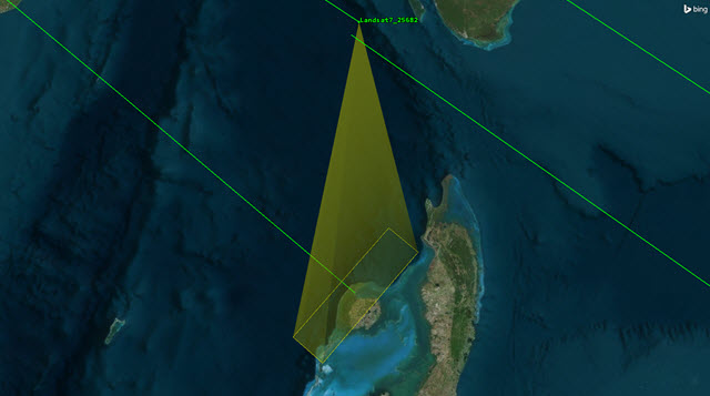
Landsat7_25682 Sensor Field of View
Group your Landsat satellites
Insert a Constellation object that groups your Landsat satellites for analysis.
- Insert a Constellation () object using the Insert Default method.
- Right-click on Constellation2 () in the Object Browser.
- Select Rename.
- Rename Constellation2 () to "Landsat_Sats".
- Right-click on Landsat_Sats ()
- Select Properties ().
- Select the Basic - Definition page within Landsat_Sat's properties.
- Enable Satellite () in the Selection filter.
- Move () the Satellite () objects from the Available Objects list to the Assigned Objects list.
- Click .
Group the cameras
You can insert a Constellation object that groups your camera for analysis.
- Insert a Constellation () object using the Insert Default method.
- Right-click on Constellation3 () in the Object Browser.
- Select Rename.
- Rename Constellation3 () to "CamerasFOV".
- Right-click on CamerasFOV.
- Select Properties ().
- Select the Basic - Definition page within CamerasFOV’s () properties ().
- Enable Sensor () within the Selection Filter.
- Move () the Sensor () objects on each Landsat from the Available Objects list to the Assigned Objects list.
- Click .
TDRS satellites
You can create a satellite constellation from within the Search Standard Object Data window. Your constellation will include the three TDRS satellites.
- Insert a Satellite () object using the From Standard Object Database method.
- Enter TDRS in the Name or ID: field when the Search Standard Object Data window opens.
- Click .
- Select TDRS 3, TDRS 5 and TDRS 10 from within the Results: list. You must have your Data Source as the AGI's Standard Object Data Service.
- Set the Insert Options frame to the following:
- Click .
- Click to exit the Search Standard Object Data window when the satellites have been propagated.
- Click Save ().
| Option | Value |
|---|---|
| Auto Select Color | on |
| Create Constellation from Selected | on |
| Name: | TDRS_Sats |
Define a Chain of events
A chain is a list of objects in order of access. Your chain can have objects as individuals or in groups as constellations.
In this analysis, you need to analyze a chain of events from: the Colosseum, to the camera field of view, then to a Landsat satellite, then to a TDRS satellite, and then to a TDRSS ground site.
- Insert a Chain (
 ) object using the Insert Default method.
 - Right-click on Chain () in the Object Browser.
- Select Rename.
- Rename Chain1 () to "Colosseum_To_Ground".
Defining the Chain's order
You need to define the order of access within the chain. The chain's order should have these qualities:
- The Colosseum must be visible.
- At least one member of the CamerasFOV () constellation must be able to see the Colosseum.
- The Landsat satellite that takes the picture must be able to transmit to a TDRS satellite.
- The member of the TDRS_Sats () constellation that receives the images can downlink to either a White Sands or Guam ground site.
To give the Chain object these qualities, follow this procedure:
- Right-click on Colosseum_To_Ground () in the Object Browser.
- Select Properties ().
- Select the Basic - Definition page within Colosseum_To_Ground's () properties.
- Move () the following objects from the Available Objects list to the Assigned Objects list in this order:
- Colosseum ().
- CamerasFOV ().
- Landsat_Sats ().
- TDRS_Sats ().
- TDRSS_Ground ().
- Ensure that the objects are in the Assigned Objects list in the order specified.
- Click .
- Click Save ().
Constrain Access to Rome
The TDRS cameras need to take pictures of the Colosseum only during daylight hours. To model this, you need to impose a constraint based on the position of the Sun.
- Right-click on Colosseum () in the Object Browser.
- Select Properties ().
- Select the Constraints - Sun page within the properties of Colosseum ().
- Enable Lighting.
- Select Direct Sun from the drop-down list.
- Click .
When can I "see" it?
Now, you can answer the original question--When will you have the opportunity to take pictures of the Roman Colosseum and relay them to White Sands or Guam in near-real-time? You can calculate the Complete Chain Access to see when the chain is active. While the chain is active, the satellite's cameras can "see" the Colosseum and will relay a picture of it.
- Click Save ().
- Right-click Colosseum_To_Ground () in the Object Browser.
- Select Report & Graph Manager (
 ).
). - Turn off Show Graphs in the Styles frame once the Report & Graph Manager () opens.
- Select Complete Chain Access in the Installed Styles list.
- Click . This may take a few moments to complete.
- Use the Complete Chain Access report to answer the following questions:
- Which date has the longest access time?
- What are the most access periods found in one period of daylight?
Visual analysis
You can look at a complete chain access in either the 2D or 3D Graphics windows.
- Right-click the first access Start Time time in the Access report.
- Hover over Start Time in the context menu.
- Select Set Animation Time.
The time of access will be different in your report because your scenario is based on relative time (Today +\-). The animation will be set to start at the beginning of the access period.
![]()
Animation toolbar with access times
Make labels visible at long distances
To obtain improved situational awareness, you can make your satellite and ground site labels visible at greater distances in the 3D Graphics window.
Satellite labels
- Select all the Satellite () objects in the Object Browser. You can hold the Ctrl key on your keyboard while clicking to select multiple satellites.
- Right-click on one of the Satellite () objects.
- Select Properties ().
- Select the 3D Graphics - Model page when the properties window opens.
- Slide the Simple Model, Label slider in the Detail Thresholds frame all the way to the right.
- Click .
Facility labels
- Select all the Facility () objects in the Object Browser. You can hold the Ctrl key on your keyboard while clicking to select multiple satellites.
- Right-click on one of the Facility () objects.
- Select Properties ().
- Select the 3D Graphics - Model page when the properties window opens.
- Slide the All slider in the Detail Thresholds frame all the way to the right.
- Click .
Target label
- Right-click on Colosseum () in the Object Browser.
- Select Properties ().
- Select 3D Graphics - Model page when the properties window opens.
- Slide the All slider in the Detail Thresholds frame all the way to the right.
- Click .
Complete Chain Access View
Now, you can view the complete chain access in the 3D Graphics window.
- Click Save ().
- Bring the 3D Graphics window to the front.
- Click the Home View in the 3D Graphics window toolbar.
- Use your mouse to obtain a clear view of the complete chain.
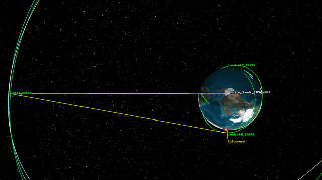
Complete Chain View
You can see that the sensor on Landsat 8 is taking a picture of the Colosseum, Landsat 8 is relaying the picture to TDRS 3, and TDRS 3 is relaying the picture to White Sands. You can also view this in the 2D Graphics window if you prefer.
What can your objects see?
You can create a report that verifies what you see in the 3D Graphics window.
You can use the Individual Strand Access report to balance timelines against accuracy of assets. For example, using this report (or graph) would help you determine the impact on your mission should any of the satellites or ground stations become inoperable.
- Close the Complete Chain Access report, if you have not already.
- Return to the Report & Graph Manager ().
- Select Individual Strand Access in the Installed Styles list.
- Click .
- Use the Individual Strand Access report to answer the following questions:
- What is the first satellite to image the Colosseum?
- If one of your Landsat satellites became disabled, would you still be able to complete the chain?
- Are all TDRS satellites used? If not, which satellites are not used?
Save your work
Since you have completed this training, don't forget to save all your hard work!
- Close any remaining report windows.
- Close the Report & Graph Manager ().
- Save () your work.