Part 5:
Add Fidelity with STK Pro
STK Pro, STK Premium (Air), STK Premium (Space), or STK Enterprise
You can obtain the necessary licenses for this training by contacting AGI Support at support@agi.com or 1-800-924-7244.
STK Pro introduces more sophisticated modeling through advanced access constraints, flexible sensor shapes, complex visibility links, more object tracks, and digital terrain data. STK Pro allows you to:
- Constrain model behavior based on motion and geographic limitations including analytical and visual terrain.
- Define advanced sensor fields-of-view and fields-of-regard using custom geometry and pointing.
- Build system networks using defined groups or sequential, multi-link relationships called "chains".
Analytical and Visual Terrain
AGI works with several sources of terrain data. When used with STK, terrain
exploits sophisticated multi-dimensional interpolation algorithms to provide accurate
360 degree azimuth-elevation masks for access calculations from any point on the
Earth's surface. These algorithms also provide altitude information for
facilities, places, and targets you define. Terrain, when used visually, allows a vivid 3D visual depiction
of the Earth's true surface relief and its effect on accesses and visibility. Terrain, when used for analysis, includes terrain elevation data in the
computation of an azimuth-elevation mask; the position of a facility,
place or target; altitude reference for an aircraft, facility, place, ship, or target;
height above ground for a facility, place or target; boundary wall for an area target
or line target.
Add Terrain and Imagery to Determine its Impact on Line of Sight Visibility
Watch the following video. Then follow the steps below, which incorporate the systems and missions you work on (sample inputs provided).
- Add Terrain and Imagery

- Create a new scenario with the default time period.
- Click create a Scenario (
 ).
). - In the New Scenario Wizard set the following options:
- Name the scenario (e.g. "STK_Pro").
- Define the analysis start and stop times or accept the defaults.
- Click OK.
- Add analytical terrain to the scenario.
- Right-click on the scenario () and open the Properties (
 ).
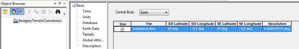
). - Select the Basic - Terrain page.
- Clear the Use terrain server for analysis check box.
- Click the Add button and browse to the terrain data file.
- Select USGS DEM (DEM) (*.dem) in the file type drop down list.
- The example file is located at <STK Install Folder>\Data\Resources\stktraining\samples
- Select hoquaim-e.dem and click Open.
- Click OK to apply changes and dismiss the Properties Browser.
- Convert the terrain data file to a terrain inlay file (*.pdtt).
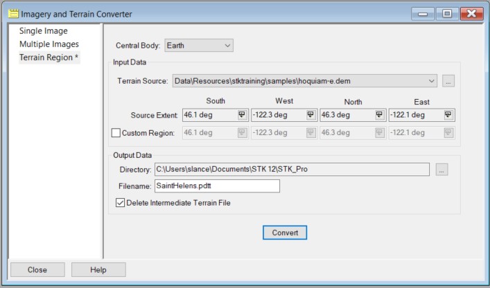
- Click the Utilities menu and select Imagery and Terrain Converter...
- Select the Terrain Region page.
- Select the Terrain Source previously loaded in the scenario from the drop-down list (e.g. hoquiam-e.dem).
- In the Output data section, click the ellipsis (
 ) button to select the Output Data Directory (e.g. current scenario directory).
 - Enter a filename (e.g. SaintHelens) in the Filename text field.
- Click Convert.
- Click Close to dismiss the Imagery and Terrain Converter.
- Add visual terrain to the scenario.
- Click the Globe Manager (
 ) icon on the 3D Graphics window toolbar or click the View menu and select Globe Manager.
 You can drag and drop .pdtt files directly onto the STK globe.
-
Click the Add Terrain/Imagery (
 ) button and select Add Terrain/Imagery (
 ) or right-click Earth in the Globe Manager and select Add Terrain/Imagery...
- Select the output data directory you chose previously from the Path drop-down list.
- Click to select the *.pdtt file (e.g. SaintHelens.pdtt) in the list.
- Click Add.
- When prompted, click Yes to enable terrain for analysis.
- Right-click on the *.pdtt file in the Globe Manager and select Zoom To.
Click the Flashlight ( ) icon on the 3D Graphics Window menu bar to brighten the terrain file if it appears to be nighttime at Mount Saint Helens.
If you have an active internet connection ( ), your imagery should be clear when zoomed in. If you do not have an active internet connection, you can instead load the preinstalled imagery using the Add Terrain/Imagery procedure and opening the St Helens.jp2 imagery file located at C:\Program Files\AGI\STK 12\STKData\VO\Textures.
- Ensure that Ground Sites Consider Terrain.
- Model a ground site (any type:
 ,
, ,
,  ) on the terrain region using one of the available insert methods (examples below).
- Insert a Place () and Search by Address (requires internet () (e.g. Mount St. Helens, WA). If you do not internet access, insert a Place and Define Properties, entering a Latitude of
46.19120 deg and a Longitude of -122.19440 deg.
- Insert a ground site (any type: ,, ) on the terrain region by using 3D Object Editing.
- Ensure the ground site (any type: ,, ) considers terrain height for its altitude.
- Right-click on the ground site (e.g. Mount_St_Helens_WA) and select Properties ().
- Select the Basic - Position page.
- Verify the Use terrain data for altitude option is checked.
- Click Apply to apply the changes and keep the Properties Browser open.
- Create and Display Terrain Obscuration.
- Return to the ground site's (e.g. Mount_St_Helens_WA) Properties Browser.
- Define an azimuth-elevation mask and use it for an access constraint.
- Select the Basic - AzElMask page.
- Select Terrain Data from the Use: drop-down list.
- Enable Use Mask for Access Constraint.
- Click Apply to apply the changes and keep the Properties open.
By enabling the Use Mask for Access Constraint option, the Az-El Mask constraint is enabled on the Constraints – Basic page.
- Display the azimuth-elevation mask at the ground site.
- Select the 2D Graphics - AzElMask page.
- Select the Show check box for the At Range option.
- Enter a max range for the mask display (e.g. ten (10) km).
- Click OK to accept the changes and dismiss the Properties Browser.
- Mouse around the 3D Graphics window to take a look at the azimuth-elevation mask display.
- Ensure a Moving Vehicle Considers Terrain.
- From the Insert STK Objects (
 ) tool, select Ground Vehicle (
 ) and choose the Define Properties method.
 - Ensure the vehicle considers terrain along its route.
- Select the Basic - Route page.
- Select Terrain in the Altitude Reference - Reference: field.
- Set a Granularity type (e.g. 0.01 km).
- Select Terrain Height as the Interp Method.
- Insert waypoints (examples below):
- Type in waypoint values.
- On the Basic - Route page, click Insert Point twice to add two waypoints manually.
- Enter values for the first waypoint (e.g. Lat = 46.23 deg, Lon = -122.23 deg).
- Enter values for the second waypoint (e.g. Lat = 46.19 deg, Lon = -122.13 deg).
- Click OK to accept the changes and dismiss the Properties browser.
- Click the waypoints in the 3D window.
- Make sure the ground vehicle's Properties Browser is closed.
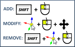
- Use the 3D Object Editing tool to model the ground vehicle's route.
- Determine if Terrain is Obscuring the View.
- Compute Access (
 ) between the ground site (,, ) and ground vehicle () and generate an Access report.
 - Click the Access () tool or extend the Analysis menu and select Access.
- On the Access page, click the Select Object... button and select the ground site (e.g. Mount_St_Helens_WA) as the Access For object (From).
- Select the ground vehicle () as the To object.
- Click the Compute button.
- Click Access... in the Reports section of the Access tool.
- Add intervals (
 ) to the Timeline View.
 - In the Timeline View toolbar, select Add Time Components (
 ).
). - Add the ground vehicle's availability time span to the Timeline View.
- Select the Ground Vehicle () on the left.
- Select AvailabilityTimeSpan in the Components for section on the right.
- Click Apply to add the availability interval to the Timeline View.
- Add the access intervals to the Timeline View.
Starting with STK 11.1, Access Intervals are automatically added to the Timeline View when calculating Access. For STK 11.1 or later, this step is not necessary and may be skipped.
- Select the Access () object on the left.
- Select AccessIntervals in the Components for section on the right.
- Click OK to add the Access Intervals to the Timeline View and dismiss the Add Time Components tool.
- Center Timeline View on the availability time span.
- Right-click on the availability time span interval.
- Select Center.
- Animate (
 ) and mouse around the 3D Graphics window to visualize when the terrain obstructs access.
 - Use the Slide Bar to scroll through the ground vehicle's route and visualize when the terrain obstructs access.
Don't forget to save your work!
 ) object.