Holding - Racetrack
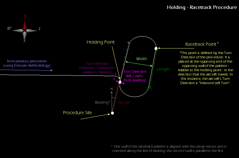
A racetrack holding procedure is a patrol in a rectangular oval. The holding point for the procedure is the point at which the aircraft enters and exits the holding circle and is the reference point for procedures that are set to end on a course to the next procedure. This holding point is defined by a bearing and range from the procedure site; the racetrack is oriented parallel to the line of bearing. The site of a holding procedure is only a reference point for the holding pattern, and may not be encompassed by the aircraft's flight path.
The procedure contains three control points - the procedure site, the Holding point, and the Racetrack point - as indicated in the diagram below. The Holding Point is placed relative to the procedure site, along the Bearing and at a distance equal to the Range. The Racetrack point is placed at the opposite end of the Holding Point, on the opposing wall of the pattern.
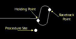
Click the image to view a detailed diagram.
Altitude
Altitude parameters define the altitude that the aircraft will attempt to achieve and sustain during the procedure.
Table - Altitude Parameters
| Parameter |
Description
|
| Use Aircraft Default Cruise Altitude
|
Select this check box to define the altitude of the procedure using the default cruise altitude specified in the currently selected cruise performance model.
|
| Altitude
|
If Use Aircraft Default Cruise Altitude is not selected, select an altitude reference (AGL or MSL) and then define the aircraft's altitude for the procedure.
The altitude is constrained by the lowest ceiling value of the active performance models in the current mission phase. |
Hold Options
| Field
|
Description
|
| Profile Mode |
The profile mode defines how the aircraft will perform during the holding pattern with respect to airspeed and altitude. Select from the following modes:
- STK 8 Compatibility Mode - The aircraft will use the selected level off maneuver and fly the pattern at the speed at which it arrived at the entry point.
- Level off, fly cruise profile speed - The aircraft will use the selected level off maneuver and fly the pattern at its cruise speed, accelerating or decelerating as necessary to achieve it.
- Allow climb/descent on station - The aircraft will climb or descend to the procedure's altitude over the course of the holding pattern, eliminating the need for a level off maneuver.
|
| Level Off Maneuver |
A level off maneuver is used to bring an aircraft to the altitude specified for a procedure, if the aircraft is unable to attain that altitude during the course of that procedure. Select from the following leveling off options:
- Automatic - STK's Aviator capability will determine if a level off maneuver is required, and the direction of the maneuver if needed.
- Left Turn - The direction of the maneuver will be a left turn.
- Right Turn - The direction of the maneuver will be a right turn.
- No Turn - A maneuver will not be performed. If a level off maneuver is required to reach the specified altitude, then the procedure will be invalidated.
|
| Bearing
|
The bearing of the holding point from the site. Specify a True or Magnetic north reference using the drop-down menu.
|
| Range
|
The distance to the holding point, which is the point at which the aircraft enters and exits the holding pattern.
|
| Width
|
The width of the holding pattern.
|
| Length
|
The distance between the centers of the pattern's arcs.
|
| Entry Maneuver |
The entry maneuver defines how the aircraft will enter the holding pattern. Select from the following maneuver options:
- No Maneuver - The aircraft will enter the holding pattern at the normal holding point.
- Use Standard Entry Turns - The aircraft will perform one of three entry turns based on the standard entry maneuvers defined in the FAA Instrument Flying Handbook; Aviator will evaluate all three standard entries and use the maneuver with the least turn angle.
- Use Alternate Entry Points - The aircraft enter the holding pattern from an alternate point rather than the holding point described above. The alternate point will be an endpoint of a straight leg, or along the arc at the end, whichever is the most efficient point to arrive at. The aircraft will exit the pattern at the holding point, as normal. If the final course of the previous procedure is set to automatically point to the next procedure, it will point at the hold point and not the entry point.
|
| Turn Direction
|
Select an option to define if the aircraft enters the hold inbound or outbound from the site along the bearing and if the aircraft turns left or right during the procedure.
|
| Number of Full Turns
|
The number of times that the aircraft will complete the holding pattern.
|
| Refuel/Dump Mode |
The Refuel/Dump mode applies when the aircraft is performing a Refuel/Dump operation during the holding pattern, and defines when the aircraft will leave the holding pattern after it has completed refueling or dumping fuel. Select from the following modes:
- Full Number of Turns - The aircraft will complete all of the turns defined for the procedure, regardless of when the operation has been completed.
- Exit at End Of Turn - The aircraft will leave the holding pattern at the end of the turn in which the operation has been completed.
- Immediate Exit - The aircraft will leave the holding pattern immediately upon completing the operation.
|
Hold Cruise Airspeed
Hold Cruise Airspeed parameters define the airspeed performance characteristics of the aircraft during the holding segment of the procedure.
Table - Hold Cruise Airspeed
| Parameter |
Description |
| Airspeed Type |
Select the method for determining the airspeed from the following options:
- Minimum Airspeed - constant airspeed at the minimum cruising airspeed for the aircraft.
- Max Endurance Airspeed - variable airspeed that maximizes the length of time that the aircraft can remain in flight.
- Max Range Airspeed - variable airspeed that maximizes the distance that the aircraft can fly.
- Max Performance Airspeed – a custom performance airspeed and fuel flow that you can use to model specific flight conditions
- Maximum Airspeed - constant airspeed at the maximum cruising airspeed for the aircraft.
- Other Airspeed - constant, manually defined airspeed.
With the exception of Other Airspeed, the actual airspeed will be defined by the currently selected cruise performance model, or possibly by the currently selected climb or descent performance model if the aircraft is climbing or descending.
|
| Airspeed |
Displays the airspeed. If the airspeed type is Other Airspeed, enter the desired airspeed value; otherwise, the calculated value will be displayed and cannot be edited. Select a reference from the drop-down menu - true airspeed (), calibrated airspeed (), equivalent airspeed (), or number. |
Enroute Options
Enroute Options define maneuvering performance characteristics of the aircraft during enroute segments of the procedure.
Table - Enroute Options Parameters
| Option |
Description |
| Delay Enroute Climbs and Descents
|
Select this check box to have the aircraft begin climbing or descending at a point in time during the procedure such that it won't achieve the new altitude until the start of the arc or pattern, or until it has reached the procedure site (whichever is applicable to the specific procedure). |
| Use Max Speed When Computing Turn Radii |
Select this check box to force the aircraft maintain its cruise speed when turning, even if doing so will result in the aircraft making a turn large enough that it takes longer to complete than it would complete a slower, smaller turn. |
| Turn Factor
|
The Turn Factor is the maximum amount - expressed as a multiplier - that the turn radius will be increased to minimize the bank angle required to complete the turn. The factor is applied only to turns that are performed enroute to the procedure's first control point. The full circles that correspond (or are tangent) to the start/stop turns at the extended radius may not intersect if the factor is set high enough. This parameter is a limit and may not actually be achieved due to the requirement to generate an appropriate turn sequence. You can adjust the slider or enter the value manually in the box, with the minimum value being 1 and the maximum value being 10. |
Enroute Cruise Airspeed
Enroute Cruise Airspeed parameters define the airspeed performance characteristics of the aircraft during enroute segments of the procedure.
Table - Enroute Cruise Airpseed Parameters
| Parameter |
Description |
| Airspeed Type |
Select the method for determining the airspeed from the following options:
- Minimum Airspeed - constant airspeed at the minimum cruising airspeed for the aircraft.
- Max Endurance Airspeed - variable airspeed that maximizes the length of time that the aircraft can remain in flight.
- Max Range Airspeed - variable airspeed that maximizes the distance that the aircraft can fly.
- Max Performance Airspeed – a custom performance airspeed and fuel flow that you can use to model specific flight conditions.
- Maximum Airspeed - constant airspeed at the maximum cruising airspeed for the aircraft.
- Other Airspeed - constant, manually defined airspeed.
With the exception of Other Airspeed, the actual airspeed will be defined by the currently selected cruise performance model, or possibly by the currently selected climb or descent performance model if the aircraft is climbing or descending.
|
| Airspeed |
Displays the airspeed. If the airspeed type is Other Airspeed, enter the desired airspeed value; otherwise, the calculated value will be displayed and cannot be edited. Select a reference from the drop-down menu - true airspeed (TAS), calibrated airspeed (CAS), equivalent airspeed (EAS), or Mach number. |
Enroute Turn Direction
Enroute Turn Direction parameters define the direction that the aircraft will turn during enroute segments of the procedure.
Table - Enroute Turn Direction Parameters
| Parameter |
Description |
| First Turn |
The direction of the turn made from the end of the previous procedure as the aircraft sets its course toward the procedure site. Select from the following options:
- Automatic - STK's Aviator capability will determine the direction of the turn.
- Turn Left - Specifies a left turn.
- Turn Right - Specifies a right turn.
|
| Second Turn |
The direction of the turn made to achieve the outbound course at the procedure site. Select from the following options:
- Automatic - Aviator will determine the direction of the turn.
- Turn Left - Specifies a left turn.
- Turn Right - Specifies a right turn.
|