VOACAP
STK's VOACAP propagation loss model combines detailed hourly predictions of the distribution of worldwide atmospheric and man-made radio noise, platform mobility models, wireless link calculations, and the mission analysis environment of STK. This fused communications analysis — using multiple layers of the ionosphere through different mission domains such as the space and ground environments — makes it easy to:
- Create a realistic scenario for HF communications modeling
- Improve the fidelity of HF communications link budget calculations
- Clarify the effects of HF signal degradation in the context of the mission
VOACAP predicts HF propagation between a transmitter and receiver at any two points on Earth over a 24-hour cycle. The VOACAP model is based on ionospheric conditions within the various layers. The condition of the ionosphere depends on:
- Solar cycle
- Season
- Diurnal cycle
- Latitude and longitude position
Propagation loss includes aspects such as:
- Electron vertical profile through each layer of the ionosphere
- Absorption losses
- Deviation losses of high angles
- E-layer bending
- E-sporadic layer obscuration loss
- Ground loss
- Auroral adjustment of median signal level
- Transmit and receive antenna gains (and for radar: target RCS)
The VOACAP model evaluates up to 11 frequencies, for 90 transmission and reception angles, for up to five hops, and up to six modes. Internally it has two compute models. One model is considered a "short-distance" algorithm, which is a quasi-ray-traced path through the atmosphere.VOACAP uses this short-distance algorithm when the great-arc path is less than 7,000 km. The other compute model is a "long-distance" algorithm, which is a more empirical path model that evaluates the transmission rather than evaluate the reception. VOACAP uses this "long-distance" algorithm for great-arc paths greater than 10,000 km. For path distances between the distances of the short-distance and long-distance algorithms, VOACAP computes both short-distance and long-distance algorithms and applies a smoothing algorithm. This smoothing is one of the major differences between IONCAP and VOACAP.
VOACAP measures the system performance at the ionospheric layer through this atmospheric absorption model by looking at parameters such as Received Isotropic Power and Eb/No, which is the Bit Error Rate. VOACAP also measures Sky Wave Propagation Loss and Delays.
Solar activity configuration
Sunspot numbers are important for satellite operators and also for signal transmission analysis and prediction. They are one of several mechanisms used to indicate the level of solar activity. A sunspot is a cooler region of the Sun, and these cooler regions have a higher magnetic field, causing higher solar activity.
In general, the higher the solar activity, the better the HF propagation and the higher the maximum usable frequency. However, high sunspot numbers can produce sudden ionospheric disturbances and traveling ionospheric disturbances.
Sunspot number
The sunspot number is computed based on observations, and its peaks and troughs are somewhat periodic on an 11-year cycle. You can find historical and future predicted sunspot numbers here:
Solar flux index
While the VOACAP model uses sunspot number as an input, if you know the solar flux index you can change the solar activity configuration to Solar Flux. STK uses ITU-R P.371 (SS 5, Eq 2) to convert between the solar flux data and the sunspot number.
It is important to set the Sunspot Number or Solar Flux based on the expected state of the ionosphere.
VOACAP parameters
| Option | Description |
|---|---|
| Man-made Noise |
Man-made noise characterizes the type of noise environment at the receive side of a link. The values associated with these are those defined by ITU-R P.372 at 3 MHz. The options include:
|
| Minimum Take-off Angle | This value is typically very small unless the antenna performance is very poor at low angles. These low angles should not be considered in the estimation of the upper useful frequencies. Also, you may increase the takeoff angle if the terrain is obstructing the low takeoff angles and reception angles. |
| Required Reliability | This is an estimate of the percent of days within the month that the signal quality is adequate. |
| Required SNR |
This option depends on the receiver specifications and is a metric for defining adequate service. VOACAP expects this to be an hourly median signal power relative to the hourly median noise in a 1 Hz bandwidth. The required SNR (signal-to-noise ratio) is estimated by the following equation: Required SNR = 10 + 10*log10(BW) BW is the receiver bandwidth. |
| Multipath Power Tolerance | This governs the amount of skywave signal power deviation that is considered across the different modes. A value of 0 dB means VOACAP will not consider multiple paths. |
| Multipath Delay Tolerance | This governs the amount of skywave signal delay deviation that is considered across the different modes. A value of zero (0) seconds means VOACAP will not consider multiple paths. |
| Coefficient Data Type | There are two coefficient data sets, CCIR and URSI. AGI recommends the CCIR coefficient set. If you select the URSI coefficient set, you can select Use Daily Average Data Set to use a daily averaging of the coefficient set. |
| Compute Alternative Frequencies | Select this option to execute the VOACAP model using the transmit frequency and 10 other frequencies spread across the HF band. The 10 frequencies are logarithmically spaced across the HF band from 2 Hz to 30 MHz. |
STK/VOACAP integration
The VOACAP model source code is written in FORTRAN and is freely available. The model, in its original form, is compiled into an executable and performs a substantial amount of file input and output. The version of VOACAP in STK has been slightly modified in order to remove the file operations and build the model into a dynamic link library for direct call from within STK. The algorithms and the model itself are unchanged.
VOACAP can execute in one of three modes: a point-to-point method, an area coverage method, and batch mode. STK uses VOACAP in a point-to-point mode.
You can use the VOACAP model to perform trade studies related to:
- Optimal location for reception
- Best time of day for reception
- Best usable frequency
- Optimal transmit and receive angles
There are a few VOACAP outputs that directly impact STK's Link Budget report. These include:
- transmit azimuth
- transmit elevation
- transmit gain
- propagation range
- propagation loss
- receive azimuth
- receive elevation
- receive gain values
There are also some VOACAP outputs that do not directly influence STK's Link Budget parameters, but which are still valuable, such as:
- reliability
- mode
- maximum usable frequency
Finally, if you want to see a VOACAP output parameter that is not included as a report element in STK's data providers, you can obtain the full VOACAP output table in the traditional VOACAP format. See the Data Providers section of the STK Help for more information.
VOACAP mode
The mode tells you what layers of the ionosphere contributed to the signal propagation. The mode also provides information about which algorithm (short-distance or long-distance) it used when determining the sky wave path. The format of the mode depends on the algorithm that you select.
Short-distance algorithm
The short-distance algorithm formats the mode as the layer name prefixed by the number of hops from that layer. For example, 3F1 indicates that there were three hops from the F1 layer; furthermore, you know that the short-distance algorithm dominated.
Long-distance algorithm
The long-distance algorithm formats the mode as two layer names. The exact number of hops is unknown because the algorithm evaluates the angles on the transmit side, then evaluates the angles at the reception side. The path between is unknown. In this case, the mode represents the layer on the transmit side followed by the layer on the receive side. For example, F1F2 indicates that the F1 layer contributed on the transmit side and the F2 layer contributed on the receive side. You know that the long-distance algorithm dominated.
Skywave Dopplers
STK VOACAP reports multiple skywave Dopplers for both communications and radar applications, but it is more prevalent to radar analysis. Therefore, the following description of skywave Dopplers is in the context of radar Doppler analysis.
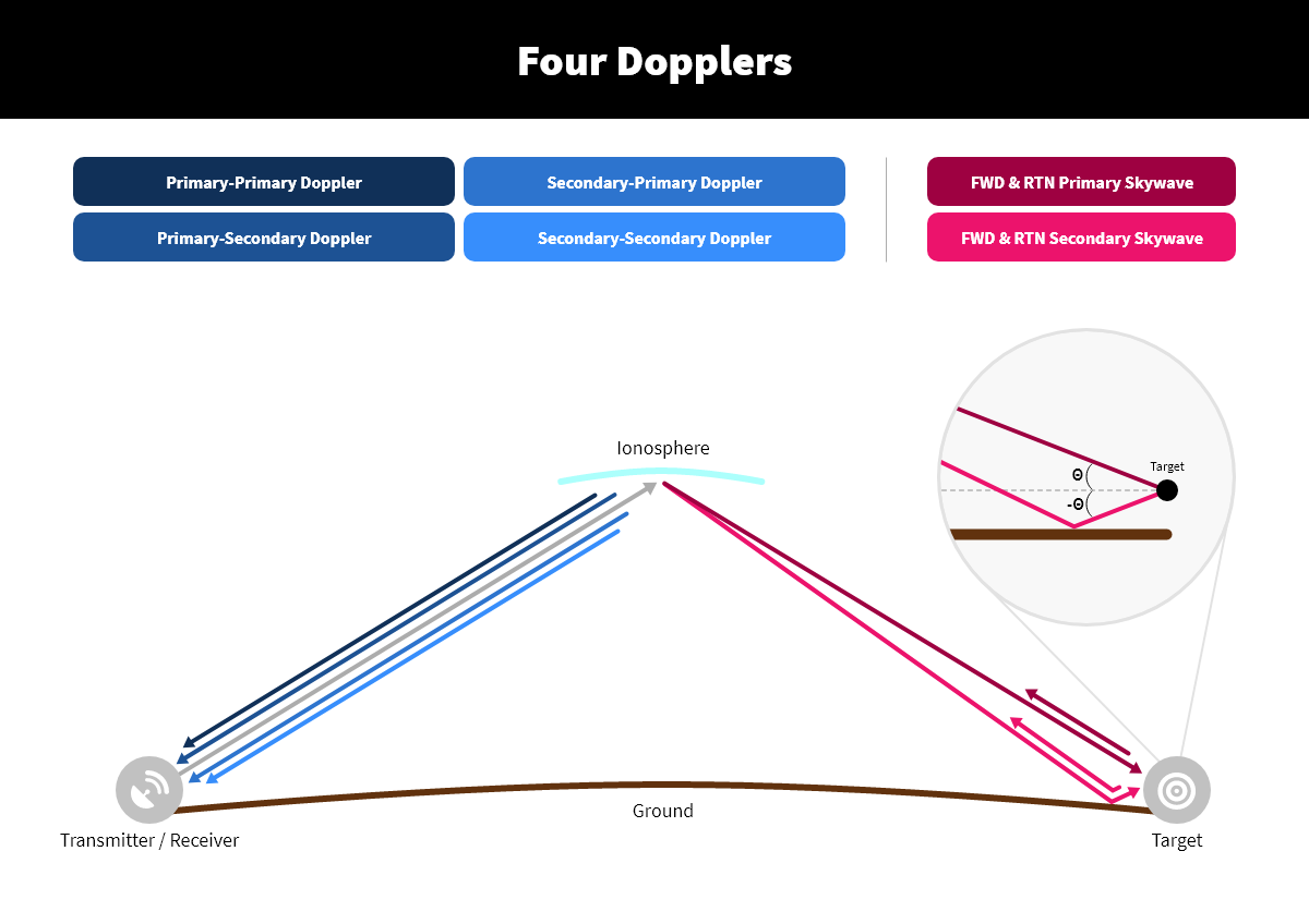
STK VOACAP assumes that the direct skywave signal impinging upon a destination target not only illuminates that target directly, but that there is an equally strong illumination from that direct skywave bouncing off the ground very close to the destination target and then hitting the target. Thus, there are two signal paths that are from the emitter to the target. The first path is the “primary” skywave, which is the path from the transmitter to target via only a skywave path (which may include multiple hops). The second path is the “secondary” skywave, which is the path from the transmitter to the target via a skywave that bounces off the ground very close to the target. If the primary skywave consists of multiple hops, then the secondary skywave path includes the same number of hops. STK assumes the distance from the emitter to the target is large such that the difference between path length of the primary and secondary skywave paths is negligible for HF purposes.
There are two paths to the target and two paths returning back to the radar, resulting in the following four Doppler types:
- Primary-Primary Doppler is from the path from emitter to target via the primary skywave and then returning from target to receiver also via the primary skywave path.
- Secondary-Secondary Doppler is from the path from emitter to target and back via a secondary skywave path. The signal bounces very close to the target before illuminating the target and bounces very close to the target again before journeying back to the receiver.
- Primary-Secondary Doppler is from the path from emitter to target via the primary skywave and returning from the target to the receiver via the secondary skywave.
- Secondary-Primary Doppler is from the path from emitter to target via the secondary skywave and then returning from target to receiver via the primary skywave.
The following figure illustrates the two skywave paths and these four Doppler paths.
For a monostatic radar situation, the return path considers the same close-in bounce at the target. So, although there are four Dopplers, two will always be the same for monostatic.
For bistatic radar, the transmit and receive capabilities are not colocated. Thus, the primary-secondary doppler and the secondary-primary dopplers will be different, giving rise to four unique Doppler values.
All the Doppler values are in the VOACAP data providers.
STK reports the secondary dopplers as if the secondary signal was strong enough to be detected. It does not determine if the signals are actually strong enough to be received or not.
System performance analysis is based on just the primary skywave path.
Limitations of VOACAP
- Since VOACAP is an over-the-horizon model, you should disable the Line-of-Sight (LOS) constraint. If the LOS constraint is not disabled, there are no access intervals.
- The frequency range of the transmitter must be between 2 MHz and 30 MHz. If the transmit frequency falls outside this range, at any time step, the Message Viewer reports an error and the model fails to execute.
- The d-layer of the ionosphere can have a significant impact on HF propagation. Since the height of the d-layer is approximately 50 km to 60 km, if either end of the circuit goes above 50 km, the model would not be applicable. If either end of the circuit goes above 50 km, at any time step, the model issues an error in the Message Viewer and the model fails to execute.
- The VOACAP model assumes circuit end points are on the ground. For long range circuits, this is reasonable since the height of the d-layer is very low in comparison to the circuit's long range.