Helix Antenna Pattern
STK Communications provides standard models for helix antennas.
1Johnson, Richard C, Antenna Engineering Handbook, 3rd ed., New York: McGraw-Hill (1993), chapter 13
2Kraus, John D., Antennas, 2nd ed., New York: McGraw-Hill (1988), chapter 7.
These models are valid under the following conditions:
- Only the axial mode of radiation is supported.
- The helix has fixed turn spacing.
- The helix has uniform diameter (tapered helices are not supported).
- The ratio of the circumference of the helix to wavelength is between 0.75 and 1.33.
- The turnspace distance is approximately equal to one-quarter of the wavelength.
- The pitch turn angle (calculated by STK) is between 12 and 15 degrees.
This antenna uses a polar coordinate system.
The following options are available for Helix antennas:
| Field | Description |
|---|---|
| Design Frequency |
This is the frequency of the antenna. The antenna design frequency is independent of the operational frequency of a transmitter, receiver, or radar. Changing the frequency of a transmitter, receiver, or radar does not update an embedded antenna's design frequency, nor vice versa. The design frequency is solely used at antenna configuration time to compute the antenna size from its max gain or beamwidth settings. A mismatch between signal frequency and antenna design frequency typically causes performance degradation. |
| Diameter | The diameter of the helix. |
| Efficiency | Specifies the efficiency factor of the antenna, varying from 0 to 100 percent. Since no antenna is perfect, the efficiency factor allows you to specify the degradation in performance. Typical values fall in the range of 70 to 90 percent. |
| Turn Spacing | The center-to-center distance between the turns of the helix. |
| Number of Turns | The total number of turns of the helix. |
| Back-Lobe Gain |
You can use back-lobe gain two different ways:
|
If you use the default frequency of 14.5 GHz (instead of a frequency in the usual range for helix operation), make sure to adjust the above parameters accordingly, e.g. 0.005 m for Diameter, 0.005 m for Turn Spacing and 10-25 as the Number of Turns.
The following illustration shows a helix antenna pattern:
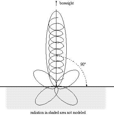
Helix antenna pattern
The radiation gain pattern is assumed to be around the axis of the Helix. Currently, it is calculated up to 90 degrees from the axis. Radiation gain toward the back direction (i.e. more than 90 degrees from the axis) is not calculated.
The default helix antenna values are good for S-band frequencies (1.0-2.5 GHz), the normal operating band for helix antennas. For other frequencies proper helix sizes must be entered.