Radars use range (or pulse travel time) based attenuation to reduce the strong returns from the nearby clutter objects.
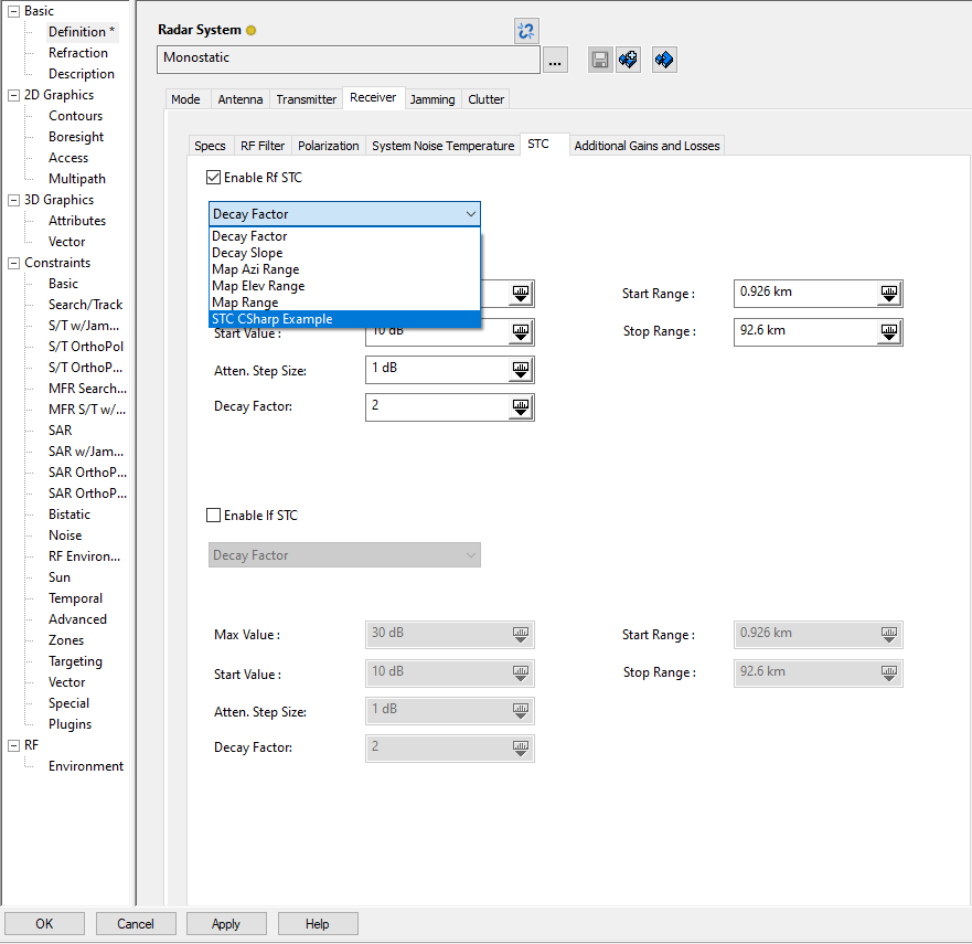
You can enable STC at Radio Frequency (RF) or Intermediate Frequency (IF) signal levels or both. You then select an STC type from one of the following categories:
Descriptions of the STC types are provided below.
Computation-based STC types
The computation based STC types are:
-
Decay Factor. STC is a factor of range. It is computed as an inverse power (decay factor) of the range to the cell of interest. For example, attenuation is decreased as a function of R-2, where R is the range and 2 is the attenuation factor. The STC attenuation is set at the STC start value at the minimum range. The attenuation is decreased as a function of the factor of the range to the cell of interest. The STC application is stopped once the attenuation value is decreased to zero dB.
-
Decay Slope. STC attenuation is stated as a decay slope, for example, 6 dB/Octave. The STC attenuation is set at the STC start value at the minimum range. The attenuation is decreased using the decay slope values until the value is zero.
The parameters for these two types are the following:
| STC Parameter | Description |
|---|---|
| Max Value (dB) | Maximum value of STC attenuation |
| Start Value (dB) | STC attenuation value at the minimum range |
| Atten. Step Size (dB) | Attenuation step size |
| Decay Factor | Attenuation decay factor, for example, R-3, where R is the range and 3 is the decay factor |
| Decay Slope / Octave (dB/octave) | Decay slope of the STC attenuation |
| Start Range | Minimum range, when STC is applied |
| Stop Range | Range at which STC is cut off; the STC attenuation value may decay to zero (dB) before the stop range depending on the decay factor or the decay slope values |
External file-based STC types
You provide the STC attenuation tables in an external STC file. Attenuation values are in dBs.
STC map types are based on ground radar systems. The azimuth and elevation angle values for the STC map types are defined based on the radar site's local horizontal reference frame.
Select one of the following STC types and enter the name of the STC file in the Filename field or click the ellipsis to browse to and select a file.
-
Map Range. You provide a table of range versus attenuation. If the range to the cell of interest is within the minimum and maximum limits of the table range, then the attenuation value is read from the table and applied. The attenuation values are NOT interpolated.
-
Map Azimuth Range. This is a two-dimensional table of azimuth versus range. Rows contain the azimuth data and the columns extend over the range. The STC attenuation is applied for all elevation angles. The attenuation values are NOT interpolated. A same attenuation value is applied over the range cells until the next range is reached in the data table.
-
Map Elevation Range. This is a two-dimensional table of elevation versus range. Rows contain the elevation data and the columns extend over the range. The STC attenuation is applied for all azimuth angles.
The external file is not automatically reloaded after you make changes to it. To reload the file, click .
Radar plugin STC type
You can create your own plugin to provide the radar STC. The data should have the same format as for an external STC file. For more information on building and registering a plugin for STK, see Extend the User Interface Using Plugins. After you have registered your radar STC plugin, it will appear as an option for Rf STC and If STC on the STC tab of a radar Receiver tab. In the following image, the radar STC plugin is called "STC CSharp Example."