EOIR Optical Properties
When you choose EOIR as the Sensor Type on the Basic - Definitions page of a sensor's properties, you can select the Optical tab to specify optical parameters for selected bands. Some optical properties appear in the general tab pane, while others appear in these subpanels:
General optical properties
You can specify the following properties on the tab; some are dependent on the selection of the input mode.
| Property | Description | ||||||||||||||||||||||||||||
|---|---|---|---|---|---|---|---|---|---|---|---|---|---|---|---|---|---|---|---|---|---|---|---|---|---|---|---|---|---|
| Input |
Choose which two optical parameters are inputs, used to calculate a third parameter. The pairing options on the shortcut menu are:
|
||||||||||||||||||||||||||||
| Auto Rebalance Parameters |
If you select this check box, EOIR will rebalance the parameters listed below to stay within their valid parameter limits. If you do not select this check box, EOIR will warn you when the settings would cause a calculation that is outside the valid parameter range. The following are the rebalanced parameters, along with their minimum and maximum limits and units.
|
||||||||||||||||||||||||||||
| F/# | Specify the F Number (Effective Focal Length/Effective Pupil Diameter) of the optical prescription. The default value is 2.0. This property is not available for Input = Focal Length and Entrance Pupil Diameter. | ||||||||||||||||||||||||||||
| Effective Focal Length | Specify the focal length (in cm) of the "single lens equivalent" optical prescription. The default is 200.0 cm. This property is not available for Input = F/# and Entrance Pupil Diameter. | ||||||||||||||||||||||||||||
| Entrance Pupil Diameter | Specify the diameter (in cm) of the "single lens equivalent" optical prescription. The default is 100.0 cm. This property is not available for Input = F/# and Focal Length. |
This diagram provides a visual definition of some terms in the table above.
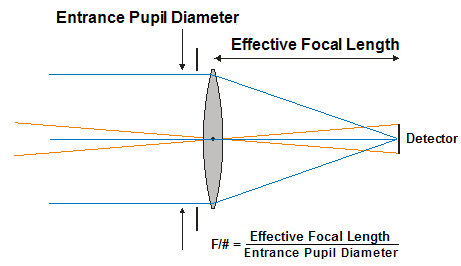
Image Quality
In the Image Quality subpanel of the Optical tab, you can specify the following properties:
| Property | Description |
|---|---|
| Input |
Choose one of the levels of image quality. The options on the dropdown menu are:
EOIR models aberrations based on a root-mean-square wavefront error: Diffraction Limited = 0.0, Negligible = 0.07, Mid = 0.14, and Moderate = 0.21. |
| RMS Wavefront Error | Specify a custom value (in waves) for the RMS wavefront error. The default is 0.0. This property is only valid for Input = Custom Wavefront Error. |
| Data File | If you choose Input as "Custom OTF/MTF" or "Custom PSF", then you must specify a data file. Click the ellipsis button to browse to and select a file. |
| Data File Sampling |
Enter a value for one of the following two sampling settings. Make the selection based on the data file that you selected.
|
| Longitudinal Defocus | You can blur the image by displacing the point of perfect focus off of the pixels by this linear distance, in mm. The default is 0.0 mm. This does not apply for Input as Custom PSF and Custom OTF/MTF. See the diagram below for a pictorial definition of this property. |

Optical Transmission
In the Optical Transmission subpanel of the Optical tab, you can specify the following properties:
| Property | Description |
|---|---|
| (method) |
Select the method of specifying the optical transmission value. The options on the shortcut menu are:
|
| Band Effective Value | Enter a value for the optical transmission as a ratio from 0.0 to 1.0. The default is 1.0. This is only applicable for Input = Band Effective Value. |
| Spectral Transmission File | Click the ellipsis button to browse to and select a spectral transmission file. This is only applicable for Input = Band Spectral Transmission Function. |
Diffraction Wavelength
In the Diffraction Wavelength subpanel of the Optical tab, you can specify the following properties:
| Property | Description |
|---|---|
| (type) |
Select the type of reference diffraction wavelength in the sensor's spectral band to use for diffraction modeling calculations. The options on the shortcut menu are:
|
| Wavelength | Enter the reference wavelength in um. This only applies to Input = User Defined. |
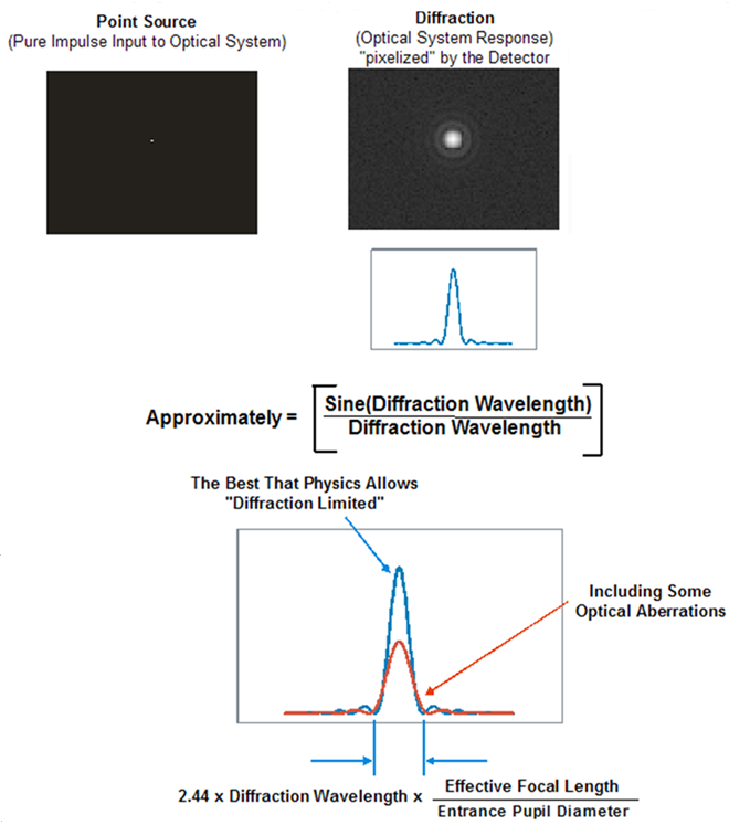
Image quality function descriptions
The following subsections describe the functions you can select for custom image quality specification.
Optical transfer function (OTF)
The optical system OTF is a product of three terms:
- The diffraction OTF
- The Hufnagle optical quality factor (OQF) - models degradations due to aberrations
- The defocus OTF
Modulation transfer function (MTF)
You can define an MTF for the detector footprint that accounts for the spatial averaging performed by individual pixels. The STK EOIR computational engine does not use detector footprint MTFs internally. However, STK does provide them in EOIR reports. Although the detector footprint MTF is not part of the computation for a sensor response to a sensor scene, defining a detector footprint MTF is still useful in that it enables a straightforward comparison of the spatial frequency filtering aspects of the detector with the optics and system-level degradations, such as line-of-sight jitter.
Point spread function (PSF)
The system PSF is the two-dimensional Fourier transform of the system OTF. You can select a grid-based, spatially-varying point spread functions within an EOIR scene generation. You can also provide a CSV file that represents the various PSFs combined and specify the rows and columns to even split the provided file in two. This way you can extract each individual PSF and associate it with a region of the simulated scene.