EOIR Radiometric Properties
The Radiometric tab is available for a sensor when you select Sensor Type as EOIR on the sensor properties Definition page. Use this tab to define the radiant energy measurement properties of the sensor.
Saturation and Sensitivity
Make selections regarding EOIR's saturation and sensitivity approach using the following setting choices:
| Setting | Description |
|---|---|
| Units of Saturation and Sensitivity |
Selecting one of the following types:
|
| Simulate Saturation | Select this check box to have EOIR simulate saturation. Then pixels can only measure up to the specified saturation level of radiant signal. This is the way physical detectors would behave. Saturation defines the "brightest" signal that the sensor can measure. |
| Simulate Quantization |
Select this check box to have EOIR simulate quantization. EOIR then performs the analog to digital conversion of the output image. To maintain realism, EOIR applies the quantization noise to the NEI/NER dark noise when you do NOT select this check box (don't simulate quantization). |
Radiometric parameter input mode
From the Input shortcut menu, select whether to use High Level or Low Level radiometric parameters.
High Level parameters
You can populate and edit sensor performance data with measurements from an actual sensor or estimates for a sensor being developed.
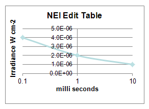
Sensitivity defines the "noise floor" of the sensor. The sensor will not detect signals below this level. Use the table in the Sensitivity section of the page to enter the following data:
| Parameter | Description |
|---|---|
| Integration Time | Enter the time in msec. For a definition of integration time, see the subsection in this topic called "Specifying an integration time." |
| Equivalent Value |
Enter the Equivalent Value for Noise Equivalent Irradiance/Radiance (NEI/NER) vs. Integration Time. To maintain realism, EOIR applies the quantization noise to the NEI/NER dark noise when you do NOT select the Simulate Quantization check box (don't simulate quantization). |
Dynamic Range is the ratio of the brightest signal to the noise floor. Use the table in the Dynamic Range section of the page to enter the following data:
| Parameter | Description |
|---|---|
| Integration Time | Enter the time in msec. For a definition of integration time, see the subsection in this topic called "Specifying an integration time." |
| Equivalent Value | Enter the Equivalent Value for Saturation Equivalent Irradiance/Radiance (SEI/SER) vs. Integration Time. |
For each of these tables, you can do the following:
- Click to add another pair to the table.
- Select a pair entry and click to delete it. STK will not allow you to remove the last remaining pair entry of either table.
Low Level parameters
Specify the following radiometric parameters:
| Parameter | Description |
|---|---|
| Quantum Efficiency Mode | Select the method for specifying the Quantum Efficiency (QE) value. The options are Band Effective and Spectral Response. |
| Spectral QE File | Click the ellipsis button to choose a file of SRF-formatted spectral profile of QE values. This is only available when you choose Spectral Response as the Quantum Efficiency Mode. |
| QE | Enter a spectrally flat band-effective quantum efficiency value in e-/photon. The default value is 1.0. This is only avaliable when you choose Band Effective as the Quantum Efficiency Mode. |
| Detector Fill Factor | This parameter is restricted to a value of 1.0, so there is no input necessary. |
| Read Noise | Enter the root-mean-square number of the electrons-per-pixel (e-/pixel) noise from reading out the charge. The default value is 1.0. |
| Dark Current Rate | Specify the average rate of accumulated dark noise per detector in e-/s pixel. |
Analog to Digital Conversion
You can specify the following parameters for converting analog to digital.
| Parameter | Description |
|---|---|
| ( method) |
Select a method for specifying the analog to digital quantization. Choose one of the following options:
where QSS is quantization step size. The noise value is specified by the equation Noise = (dark current * integration time) + read noise, which becomes the QSS. |
| Full-Well Capacity | Specify the maximum number of electrons per detector (e-/pixel), i.e., where a detector will saturate. The default value is 100,000.000, and the maximum value is 1e15. This only applies to the Full-Well methods. |
| Digital Bit-Depth | Specify the number of bits to quantize the dynamic range of the signal into digital counts. The default value is 8. This only applies to the Bit-Depth methods. |
| Quantization Step Size | Specify the number of electrons per digital count in the quantized digital output. The default value is 100.0, and the maximum value is 1e12. This only applies to the Bit-Depth methods. |
Specifying an integration time
When preparing to take measurements with the sensor model, you specify an Integration Time. This is the time interval over which a radiant signal is collected before generating an image. The longer the time, the more photons get collected. This field is equivalent to the "exposure time" setting on an old analog film camera.
The sensor model uses the Integration Time to interpolate into the Edit tables to compute Dynamic Range and NEI/NER and SEI/SER. In the case where the selected Integration Time is outside of the bounds of numbers entered in the table or there was only a single point entered, a physics-based approximation is used to extrapolate Dynamic Range, NEI/NER, and SEI/SER.