Basic Constraints
Basic Constraints enable you to impose standard access constraints on an object. You can also opt to exclude time intervals that satisfy a given constraint.
When an access involves a child object (i.e., sensor, transmitter, receiver, antenna, or radar), use the child object's parent or grandparent in the table below to determine whether the constraint can be used for access to that child object. For example, if a constraint can be used for accesses to all vehicles, then that constraint can also be used for any child object of a vehicle.
In the following table, abbreviations in the "Constraints used for accesses to..." column are:
| F = facility | Pl = place | T = target | V = all vehicles | S = satellite | M = missile | L = launch vehicle |
| A = aircraft | Sh = ship | AT = area target | LT = line target | P = planet | St = star |
| Constraint | Description | Constraint used for accesses to... |
|---|---|---|
| Azimuth Angle | For facilities and targets, STK measures azimuth in the local horizontal plane, tangent to the surface of the central body. This angle is measured from the local north direction toward the local east direction. An azimuth of 0 degrees specifies a location directly to the north, and an azimuth of 180 degrees specifies a location directly to the south. For ships, ground vehicles, and aircraft, STK measures the azimuth from the projection of the earth-fixed velocity vector. In the case where the vehicle is stationary, STK measures azimuth from local north in the topocentric frame. For other objects, STK measures azimuth in the plane perpendicular to nadir from the projection of the inertial velocity vector to the projection of the relative position vector. This angle is measured in a positive sense according to the right-hand rule about the nadir vector. An azimuth of 0 degrees specifies a location directly in front of the object, and an azimuth of 180 degrees specifies a location directly behind the object. |
F Pl T P St V |
| Azimuth Rate | The azimuth rate is the rate of change of the azimuth angle. | F Pl T P St V |
| Angular Rate |
The angular rate is defined as the angular rate of the direction of the apparent relative position between the two objects, as observed by the owner of the constraint. Let r represent the apparent relative position and v represent the apparent relative velocity. Then the angular rate ω is h⁄r2, where r=||r||, h=||h||, and h = r ⨯ v. Facilities, Targets, and Places observe and measure v in central body fixed coordinates; vehicles observe and measure v in central body inertial coordinates.
|
F Pl T V P St |
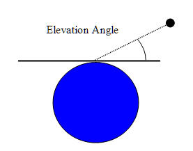
| Elevation Angle | For objects other than facilities and targets, elevation is measured as the angle between the nadir vector and the relative position vector minus 90 degrees. The elevation angle is positive for objects above the plane perpendicular to nadir. For facilities and targets, elevation is measured as the angle above the local horizontal plane, where the local horizontal plane is tangent to the surface of the central body. The elevation angle is positive for objects above the local horizontal plane. |
F Pl T P St V |
|
Elevation Angle constraint as applied to a satellite
Elevation Angle as defined for a facility or target |
||
| Elevation Rate | The elevation rate is the rate of change of the elevation angle. | F Pl T P St V |
| Altitude | Access to the object is constrained by minimum and maximum altitude specified by the constraint. For cases in which ships or ground vehicles have a constant altitude that is near or equal to the minimum altitude constraint, numerical noise may determine access times and yield no access. In these circumstances, you should set the minimum altitude value to just under the desired constraint. For example, for a desired minimum constraint of 50 m, set the minimum altitude to 49.99m so that the object will show access when at the exact desired minimum constraint altitude. |
All |
| Range | The range is measured as the distance between the two objects. | F Pl T V |
| Range Rate | Range rate is the component of the relative velocity along the line of sight of the two objects. | F Pl T V |
| Propagation Delay | Access to the object is constrained by the minimum and maximum time it takes the signal to travel between the two objects. | F Pl T V |
| Line of Sight |
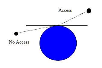
If you select this check box, STK limits the access to the object to lines of sight not obstructed by the ground. The Line of Sight ground model differs by object class. For more insights, see the subsection More on the Line of Sight constraint. |
AT LT F Pl T P St V |
|
Line of Sight constraint as applied to satellites
Line of Sight constraint as applied to a facility, ground vehicle, ship, or target |
||
| Terrain Mask | If you select this check box, STK constrains access to the object by any terrain data in the line of sight to which access is being calculated. See comparison with AzEl Mask. | F Pl T P St V |
| 3DTiles Mask | If you select this check box, access to the object is constrained by any 3D Tileset data in the line of sight to which access is being calculated. | F Pl T P St V |
| AzEl Mask | If you select this check box, STK constrains access to the object by azimuth-elevation masking. The mask used can come from terrain or a custom az-el mask as defined in the basic properties of the facility, place, or target. See comparison with Terrain Mask. | F Pl T V P |
| Field of View | If you select this check box, STK denies access if the associated object is not within the field of view as defined by the angle settings for the sensor type in question. It is independent of the same setting on the parent object. If enabled, this constraint looks at the parent sensor properties. | All |
| Sensor AzEl Mask | (Sensors only) If you select this check box, STK constrains access to the object by azimuth-elevation masking relative to the sensor's parent's body frame. The custom az-el mask used can come from an azimuth-elevation mask file (.aem) or a body mask file (.bmsk), as defined in the Basic- SensorAzElMask properties of the sensor. | F Pl T P St V |
| Use this Maximum Time Step in Access Computations | If you select this check box, access computations will have a maximum time step that you specify in the adjacent field. | All |
Constraints and parent-child object relationships
STK computes access using the constraints that you applied to the pair of objects that are the subjects of the access computation. An object that is the child of another, such as a sensor attached to a facility, does not inherit imposed constraints from its parent. In some instances, such as an access computation with constraints that are only dependent on position and in which the children objects do not have translational offsets, you can use a parent object as a proxy for its children objects to compute access more efficiently.
More on the Line of Sight constraint
The Line of Sight constraint computes whether or not the ground obstructs the line of sight between two objects, using a simple ground model. Higher fidelity ground models are available using the AzElmask or TerrainMask constraints. The Line of Sight ground model differs by object class.
| Object Class | Line of Sight Constraint Description |
|---|---|
| AreaTarget/LineTarget | STK models the Line of Sight constraint by considering each of its edge points. STK considers an edge point unobstructed by the ground if its elevation to the other object is greater than 0 degrees. If you select the "Access to Whole Object" check box, then every edge point is required to meet this condition. |
| Planet/Star | Neither object has a ground model of itself, so if you enable the Line of Sight, then STK uses the other object's Line of Sight computation. In addition, STK models a planet at its center point. If the planet's central body is the same as the central body of the other object in the access computation, then the planet's line of sight is not obstructed by the planet's surface. |
| AboveGround vehicles (Aircraft/Satellite/LaunchVehicle/Missile) | These objects use a simple ellipsoid model of the ground, using its central body shape. |
| Surface vehicles (GroundVehicle/Ship) | Normally these vehicles use a simple ellipsoid model of the ground, using its central body shape. However, the ellipsoid is reduced when the altitude is negative so that a vehicle always remains on or above its ground model. Vehicles located on the surface of their ground model effectively compute a minimum elevation angle constraint of zero to model line of sight. |
| Ground locations (Facility/Place/Target) | These objects model the ground as the ellipsoid passes through their ground position with the same surface normal vector as that of
its central body ellipsoid shape. A facility, place, or target configured with nonzero height above ground may look
downward from that height to its ground model. As of STK 6.1, if you enable the AzElMask constraint, then the ellipsoid model of the ground will be reduced so that so that it does not interfere with the AzElMask's model of the ground. The Line of Sight constraint serves as a prefilter before STK applies the AzElMask constraint, to enhance computational speed. STK 11.6 (and later) applies this same reduction in the Line of Sight ellipsoid if you enable the TerrainMask, so that it doesn't interfere with the TerrainMask's model of the ground. |
Because the objects involved in an Access computation may use different ground models, STK employs a set of rules to resolve differences to ensure accuracy. In situations where both objects have the Line of Sight constraint enabled, it may be the case that one constraint is preferred over another so that STK ignores the Line of Sight constraint enabled by one object.
| Type of Access | Line of Sight Constraint Description |
|---|---|
| Accesses involving a Planet/Star | As of STK 11.6, if the other object has a Line of Sight, Terrain Mask, or Az-El Mask constraint enabled, then STK will ignore the Planet/Star Line of Sight computation so that it can apply the other object's model of the ground correctly. |
| Accesses involving objects with different central bodies | In this case, STK will compute the Line of Sight constraint for each object. |
For accesses involving objects with the same central body, sometimes STK will ignore one object's Line of Sight constraint, depending on the class of objects involved.
| AboveGround Vehicles | Line of Sight Constraint Description |
|---|---|
|
To AboveGround vehicles |
Each vehicle uses the same ground model. STK will only compute one line of sight. |
| To Ground vehicles | STK will ignore the AboveGround vehicle's Line of Sight model in deference to the Ground vehicle's Line of Sight model. |
| To Ground locations | STK will ignore the AboveGround vehicle's Line of Sight model in deference to the Ground location's Line of Sight model. |
| To AreaTargets/LineTargets | STK will ignore the AboveGround vehicle's Line of Sight model in deference to the AreaTarget/LineTarget Line of Sight model. |
| Ground Vehicles | Line of Sight Constraint Description |
|---|---|
|
To AboveGround vehicles |
STK will ignore the AboveGround vehicle's Line of Sight model in deference to the Ground vehicle's Line of Sight model. |
| To Ground vehicles | STK will compute each vehicle's Line of Sight model. However, their models of the ground may be different. |
| To Ground locations | STK will compute both Line of Sight models. However, their models of the ground may be different. |
| To AreaTargets/LineTargets | STK will ignore the Ground vehicle's Line of Sight model in deference to the AreaTarget/LineTarget Line of Sight model. |
| Ground Locations | Line of Sight Constraint Description |
|
To AboveGround vehicles |
STK will ignore the AboveGround vehicle's Line of Sight model in deference to the Ground location's Line of Sight model. |
| To Ground vehicles | STK will compute both Line of Sight models. However, their models of the ground may be different. |
| To Ground locations | STK will compute both Line of Sight models. However, their models of the ground may be different. |
| To AreaTargets/LineTargets | STK will ignore the Ground location's Line of Sight model in deference to the AreaTarget/LineTarget Line of Sight model. |
For a more complete discussion of the Line of Sight constraint, see Line of Sight (PDF).
Facilities, targets, and places may also model the ground using an Az-El Mask constraint or a Terrain Mask constraint. If these masks allow negative elevations, then these models would conflict with the simple ellipsoid model of the ground used by the Line of Sight constraint. The other constraints’ models are considered to be of higher fidelity than the simple ellipsoidal ground model. For this reason, the Line of Sight constraint has been modified so that its ellipsoid shape no longer conflicts with the ground models used by these constraints. The deconfliction between the Line of Sight and Az-El Mask was introduced in STK 6.1; the deconfliction between the Line of Sight and Terrain Mask was introduced in STK 11.6.
When you enable both the Line of Sight and Az-El Mask or when you enable both the Line of Sight and the Terrain Mask, then the access results are the same as if you did not enable the Line of Sight at all. The presence of the Line of Sight constraint, however, follows for faster computations even though the access intervals will ultimately be determined by the Az-El Mask or Terrain Mask constraints.
When computing an access from a facility, place, or target that is configured to use an Az-El Mask or TerrainMask constraint, you should also turn on the facility/place/target Line of Sight constraint. This ensures that the ground will be modeled correctly, using the Az-El Mask or Terrain Mask in preference to the ellipsoidal ground model, should any modeling mismatches occur. If you clear the Line of Sight on the facility/target/place but leave Line of Sight enabled for the other access object, then STK will include the other object’s model of Line of Sight in the computation, possibly conflicting with the Az-El Mask or Terrain Mask. When you enable the Line of Sight constraint on the facility/target/place, STK will use its Line of Sight computation in preference to a vehicle’s Line of Sight model, so that it won’t conflict with the Az-El Mask or Terrain Mask constraints.
AzEl Mask or Terrain Mask
When using a Facility, Place, or Target object in an access computation, you can account for obscuration of the line of sight by terrain in one of two ways: selection of the Terrain Mask constraint or selection of the AzEl Mask constraint. While both constraints serve to model the same physical obstruction, there are important differences between the constraints that you should consider when selecting between the two.
Advantages and disadvantages of the AzEl Mask constraint
The AzEl Mask constraint leverages a provided or computed AzEl Mask to determine visibility. The mask may be computed from terrain information to be representative of terrain based visibility restrictions. You can construct terrain-based AzEl masks by extending a number of rays in directions of constant azimuth outwards from the facility, place, or target location. Obstruction information is stored along each ray. During visibility computations, STK uses obstruction information from the two rays that bound the current direction of interest to compute an interpolated visibility metric.
The main advantages of the AzEl Mask constraint are:
- STK computes the mask once and can store and apply it to all subsequent access computations.
- You can share the mask with the scenario without needing to share the source terrain information.
- You can visualize the mask.
- The mask accounts for all geometries, making it easily applicable to moving objects.
- It is a good option for ground stations.
The disadvantages of the AzEl Mask constraint are:
- The up-front computation of the mask is computationally expensive, especially in coverage applications where STK applies the constraint to the coverage grid points.
- Since STK uses interpolation to determine instantaneous visibility, the results are not exact.
Advantages and disadvantages of the Terrain Mask constraint
The Terrain Mask constraint determines instantaneous visibility based on detecting intersections of the instantaneous line of sight with the terrain surface.
The main advantages of the Terrain Mask constraint are:
- There are no wasted computations; STK only computes obscuration in directions of interest.
- The constraint is extremely efficient for cases where the two objects are statically located in the central body fixed reference frame.
- STK does not need to use interpolation, so results are of the highest possible fidelity.
- STK only needs to apply the constraint to one end object for cases where the two objects are statically located in the central body fixed reference frame.
The disadvantages of the Terrain Mask constraint are:
- STK must evaluate each line of sight against the terrain during visibility computations to moving objects.
- You must include terrain information when sharing a scenario.
- There is no related visualization capability.
Recommended use cases
- Use Az El Mask for ground station visibility to a constellation of satellites.
- Use Terrain Mask for cell tower visibility to the local area (using coverage).