Az-El Orientation Method | Quaternion Orientation Method | Euler Angles Orientation Method | YPR Angles Orientation Method
Orientation Methods
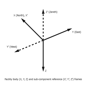
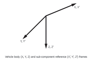
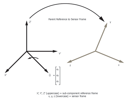
Several different orientation methods are available for specifying the direction in which a sensor or antenna is pointing with respect to a reference frame fixed in the body frame of the sensor's or antenna's parent object (vehicle, facility, etc.). This topic refers to this parent body-fixed reference frame as the subcomponent reference frame. The options available and the data that you must provide depend on the orientation method you select. Each method defines the orientation of the sensor or antenna body frame with respect to the subcomponent reference frame. The orientation of the sensor or antenna with respect to other coordinate frames (e.g., central body inertial or central body fixed) will depend on the attitude of its parent object. For example, the default attitude for an Earth orbiting satellite is "Nadir alignment with ECI velocity constraint", which points the satellite's Z axis toward the Earth. Hence, it is reasonable to set the nominal boresight direction of a satellite-based sensor or antenna to be along the Z axis to facilitate Earth viewing. On the other hand, setting the nominal boresight along the Z axis of a facility is not convenient as it will also be pointed toward the Earth. A better nominal direction in this case is along the negative Z axis. The subcomponent reference frame is selected for various STK objects in such a way that using nominal boresight direction along the reference Z axis is reasonable. For a vehicle, the subcomponent reference frame coincides with the vehicle body frame, which is the frame defined by the vehicle attitude. For a facility, the subcomponent reference frame is offset from the facility body frame by a 180 degree rotation about the body X-axis.
The subcomponent reference frame mentioned above is introduced only to simplify definitions of sensor and antenna orientation. Subcomponent reference frames are not actual frames within STK.
For fixed sensors, you can choose from the following orientation methods:
- Az-El
- Euler Angles
- Quaternion
- YPR Angles
Descriptions for these choices and their accompanying parameters are in subsections below. STK provides the following default values:
Az-El orientation method
Azimuth = 0 deg
Elevation = 90 deg
About Boresight = Rotate
Quaternion orientation method
qx = 0
qy = 0
qz = 0
qs = 1
Euler Angles orientation method
Euler A = 0 deg
Euler B = 0 deg
Euler C = 0 deg
Sequence = 313
YPR Angles orientation method
Yaw = 0 deg
Pitch = 0 deg
Roll = 0 deg
Sequence = YPR
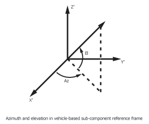
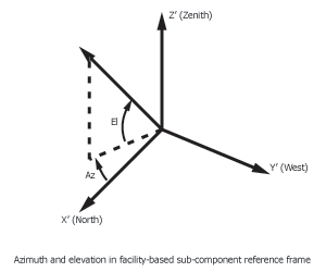
Az-El orientation method
- Azimuth is measured from the X axis in the XY plane of the subcomponent reference frame about its Z axis in the right-handed sense for vehicle-based sensors and in a left-handed sense for facility-based sensors.
- Elevation is defined as the angle between the XY plane of the subcomponent reference frame and the sensor or antenna boresight measured toward the positive Z axis.
About boresight
The sensor's or antenna's Z axis always coincides with its boresight direction and is unambiguously defined by the azimuth and elevation. However, orientation of the other two axes with respect to the parent's reference frame is determined by the About Boresight option. You can set About Boresight to:
Rotate
This indicates rotation about the Z axis of the subcomponent reference frame by the azimuth angle, followed by rotation about the new Y axis by 90 degrees minus the elevation angle. If you are familiar with Euler angle sequences, you will recognize this as a 323 rotation sequence, where the first rotation is by the azimuth angle, the second rotation is 90 degrees minus the elevation angle, and the third rotation angle is zero.
When you set About Boresight to Rotate, the complete orientation of the sensor or antenna fixed frame is as follows:
- The Z axis is aligned with the boresight.
- The Y axis runs along the intersection of the subcomponent reference XY plane and the parent body XY plane.
- The XY plane is perpendicular to the sensor or antenna boresight so that it forms an azimuth angle with the parent reference Y axis.
The X axis, also referred to as the "Up vector," completes the right-handed sensor or antenna frame. It is also evident from the following figures that for the default orientation of elevation = 90 deg and azimuth = 0 deg, the sensor or antenna frame coincides with the subcomponent reference frame:

The direction cosine matrix between the sensor or antenna frame and the vehicle body frame with the About Boresight set to Rotate is defined in terms of Az and El as:
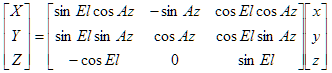
Therefore, for a sensor or antenna pointing along the vehicle axes, the corresponding Azimuth and Elevation values are:
| Boresight Direction | Azimuth (deg) | Elevation (deg) |
|---|---|---|
| +X | 0 | 0 |
| -X | 180 | 0 |
| +Y | 90 | 0 |
| -Y | -90 | 0 |
| +Z | 0 | 90 |
| -Z | 0 | -90 |
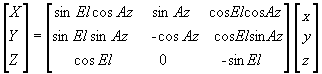
The direction cosine matrix between the sensor or antenna frame and the facility body frame with the About Boresight set to Rotate is defined in terms of Az and El as:
Hold
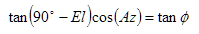
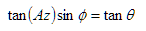
This indicates rotation about the Y axis of the subcomponent reference frame followed by rotation about the new X axis. This is equivalent to a 213 Euler angle sequence, where the third rotation angle is zero. The Hold option produces the same boresight as the Rotate option, which is defined by the azimuth and elevation angles as described above. However, the other two axes, X and Y, are obtained via the 213 sequence of Euler rotations with the last Euler angle set to zero. In other words, the Euler rotations are sought first about Y’, and then about X such that they produce the Z axis along the boresight direction prescribed by the azimuth and elevation.
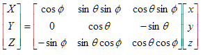
The direction cosine matrix between the sensor or antenna frame and the vehicle body frame with About Boresight set to Hold is defined in terms of the following two angles:
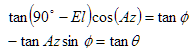
which can be determined as functions of azimuth and elevation as follows:
The direction cosine matrix between the sensor or antenna frame and the facility body frame with About Boresight set to Hold is defined in terms of the following two angles:
Level
TheLevel option for About Boresight is available only for targeted tracking sensors and is designed to minimize rotation of sensor pattern on the ground. Level indicates that the boresight is aligned with the line of sight to the target, while the sensor's X axis is constrained to be in the plane parallel to the meridian plane passing through the target.
UpVector
The About Boresight UpVector option is available only for targeted tracking sensors. STK uses it to constrain the sensor’s X axis to the direction of the specified vector, offset by the specified clock angle. The clock angle offset is measured in the sensor body XY plane, positive about the boresight, locating the direction from the sensor body X axis of the projection of the constraint vector into the XY plane.
Quaternion orientation method
The Quaternion Method is based on a unit rotation vector and its corresponding angle through which the parent reference frame is rotated in order to align it with the sensor or antenna frame.
Quaternion Method Geometry
The Quaternion is defined as:
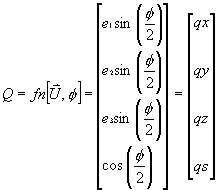
where
 is the unit rotation vector [e1, e2, e3] expressed in the spacecraft frame about which the spacecraft frame is rotated, and
  is the angle through which the parent reference frame is rotated until it is aligned with the sensor or antenna frame.
Specify the vector and scalar components of the quaternion describing the rotation from the parent object's reference frame to the sensor or antenna body frame. The vector components are qx, qy, and qz, and qs is the scalar component. The quaternion must have unit length.
Euler Angles orientation method
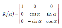
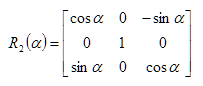
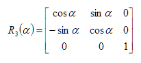
The Euler Angles method uses a three-rotation sequence about a local axis starting from the subcomponent reference frame and rotating to the sensor or antenna frame, where the initial sensor or antenna boresight is along the Z axis of the subcomponent reference frame as shown in the figure above. The sequence of three rotations is defined about either the X, Y, or Z axis, where X=1, Y=2, Z=3. Hence, a ZXZ sequence is defined as 313.
The overall transformation is a combination of three single-axis rotations about moving axes. Each of these rotations is defined in the following table:
Rotation About X-axis by angle  |
Rotation About Y-axis by angle |
Rotation About Z-axis by angle |
|
|
|
STK provides all possible sequences for combinations of the ijk sequence: 121, 123, 131, 132, 212, 213, 231, 232, 312, 313, 321 and 323.
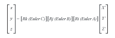
To determine the direction cosine matrix between the sensor or antenna frame and the subcomponent reference frame, the transpose of the above equations would be required as:

YPR Angles orientation method
Similarly to Euler Angles, the YPR Angles method specifies attitude using three rotations in a chosen sequence: the rotation about the reference X axis is called roll (R), the rotation about the reference Y axis is called pitch (P), and the rotation about the reference Z axis is called yaw (Y). Sequences are identified using either numbers (1 is the X axis, 2 is the Y axis, 3 is the Z axis) or letters (R is the X axis, P is the Y axis, Y is the Z axis). Unlike Euler angles, the rotations are not made about axes defined by an earlier rotation. Instead, each rotation is made about the reference system's axes.
The following example shows how YPR angles are related to Euler angles. A YPR sequence 123 and angles A, B, and C produce the following rotations in order:
- Rotate by angle A about the X axis of the reference axes
- Rotate by angle B about the Y axis of the reference axes
- Rotate by angle C about the Z axis of the reference axes
In this example, the resulting attitude is the same as produced by an Euler rotation by angles A, then B, and then C using the Euler sequence 321.
In YPR angles, the names yaw, pitch, and roll do NOT refer to the angles normally used in aviation; the terms yaw, pitch, and roll in aviation refer to 321 Euler angles.