STK Pro, STK Premium (Air), STK Premium (Space), or STK Enterprise
You can obtain the necessary licenses for this tutorial by contacting AGI Support at support@agi.com or 1-800-924-7244.
The results of the tutorial may vary depending on the user settings and data enabled (online operations, terrain server, dynamic Earth data, etc.). It is acceptable to have different results.
This lesson requires an internet connection and version 12.8 of the STK software or newer to complete.
Capabilities covered
This lesson covers the following capabilities of the Ansys Systems Tool Kit® (STK®) digital mission engineering software:
- STK Pro
- Analysis Workbench
Problem statement
Mission planners and operators need a quick way to determine the response time of a U.S. Coast Guard search and rescue mission. Distress beacons are picked up by the National Oceanic and Atmospheric Administration (NOAA) Search and Rescue Satellite Aided Tracking (SARSAT) satellite system. Once the distress call is confirmed, a rescue helicopter is dispatched to the distress beacon's location. You want to understand how long it will take for the helicopter to reach the disabled watercraft once the distress call has been received.
Solution
Use the Analysis Workbench capability's Time Tool to analyze the response time of the search and rescue mission. Add the individual steps as time-based events to the Timeline View in your analysis. From the issuing of the distress call to dispatched helicopter, each event will occur in a series, one triggering the next.
What you will learn
Upon completion of this tutorial, you will be able to:
- Add time components to the Timeline View
- Use the Analysis Workbench capability's Time Tool
- Create different time components, including Time Instants, Intervals, and Interval Lists
Video guidance
Watch the following video. Then follow the steps below, which incorporate the systems and missions you work on (sample inputs provided).
Creating a new scenario
First, you must create a new STK scenario.
- Launch the STK application (
 ), then build from there.
 - Click
 Create a Scenario in the Welcome to STK dialog box.
 - Enter the following in the STK: New Scenario Wizard:
- Click when you finish.
- Click Save (
 ) when the scenario loads. The STK application creates a folder with the same name as your scenario for you.
 - Verify the scenario name and location in the Save As dialog box.
- Click .
| Option | Value |
|---|---|
| Name | SAR_Response |
| Location | Default |
| Start | 15 Dec 2023 16:00:00.000 UTCG |
| Stop | + 1 day |
Save (![]() ) often during this lesson!
) often during this lesson!
Disabling Terrain Server
You will not use streaming terrain in your analysis, so you can turn off the Terrain Server.
- Right-click on SAR_Response () in the Object Browser.
- Select Properties (
 ).
). - Select the Basic - Terrain page when the Properties Browser opens.
- Clear the Use terrain server for analysis check box.
- Click to accept your change and to close the Properties Browser.
Setting the distress call's location
Use a
Inserting a new Target object
Create a new Target object and name it DistressLocation.
- Select Target (
 ) in the Insert STK Objects Tool.
 - Select the Insert Default () method.
- Click .
- Right-click on Target1 () in the Object Browser.
- Select Rename in the shortcut menu.
- Rename Target1 () DistressLocation.
Setting the geographic location of the distress call
The distress location is in the Atlantic Ocean east of New England.
- Open DistressLocation's () Properties ().
- Select the Basic - Position page when the Properties Browser opens.
- Set the following in the Position panel:
- Click to accept your changes and to close the Properties Browser.
| Option | Value |
|---|---|
| Latitude | 43 deg |
| Longitude | -70 deg |
Inserting the NOAA SARSAT satellites
NOAA weather satellites that are part of the SARSAT system detect and relay distress signals from emergency beacons to the appropriate search and rescue authorities. This tells agencies like the U.S. Coast Guard who is in trouble and where they are. Create a
- Insert a Satellite (
 ) object using the From Standard Object Database (
 ) method.
 - Enter NOAA in the Name or ID field when the Search Standard Object Data dialog box opens.
- Click .
- Select the following satellites in the Results list:
- NOAA_20_JPSS-1_43013
- NOAA_21_JPSS-2_54234
- Noaa19_33591
The NOAA-20 and NOAA-21 satellites (also known as JPSS-1 and JPSS-2, respectively) are part of the Joint Polar Satellite System (JPSS) and orbit the Earth from pole to pole. The NOAA-19 satellite is in a sun-synchronous orbit.
- Select the Create Constellation from Selected check box in the Insert Options panel.
- Enter NOAA_Sats in the Name field.
- Click .
- Click to close the Search Standard Object Data dialog box once the Satellite objects are propagated.
Removing an unneeded sensor
The Noaa19_33591 satellite was imported with an attached Sensor object, which isn't used in your analysis. You can remove it from your scenario.
- Right-click on Noaa19_Avhrr3_Vir_FixedPt_FieldOfView (
 ) in the Object Browser.
 - Select Delete (
 ) in the shortcut menu.
 - Click to confirm in the Delete Object dialog box.
Modeling the distress beacon's routing
A
Inserting a new Chain object
Create a Chain object that starts at DistressLocation and ends at the NOAA_Sats constellation.
- Insert a Chain (
 ) object using the Insert Default () method.
 - Rename Chain1 () DistressCall.
Defining the chain's start and end objects
Start by choosing the start object and end object in your chain.
- Open DistressCall's () Properties ().
- Select the Basic - Definition page when the Properties Browser opens.
- Click the Start Object ellipsis (
 ).
). - Select DistressLocation () when the Select Object dialog box opens.
- Click to confirm your selection and to close the Select Object dialog box.
- Click the End Object ellipsis ().
- Select NOAA_Sats (
 ) in the Select Object dialog box.
 - Click to confirm your selection and to close the Select Object dialog box.
Creating the Chain object's connections
After you choose the start and end objects in your chain, you need to build the chain's connections. It doesn't matter in which order you place the connections in the Connections list. What matters is the From Object must be able to access the To Object. In this simple chain, the from and to objects are your start and end objects.
- Click in the Connections panel.
- Click the From Object ellipsis ().
- Select DistressLocation () in the Select Object dialog box.
- Click to confirm your selection and to close the Select Object dialog box.
- Click the To Object ellipsis ().
- Select NOAA_Sats () in the Select Object dialog box.
- Click to confirm your selection and to close the Select Object dialog box.
- Click to accept your changes and to close the Properties Browser.
Building time components using the Time Tool
You will build time components for the mission using the Analysis Workbench capability, which comprises four application-wide tools that you can use to create custom components and insert them into your scenarios. One of these tools, the
- Interval List: A set of intervals, such as access intervals
- Collection of Interval Lists: A group of related Interval Lists, such as lighting intervals like Direct Sun, Umbra, and Penumbra intervals
- Time Arrays: A set of Time Instants, such as threshold crossings and acquisition Of signal times
You can use the
- Click Add Time Components (
 ) in the Timeline View toolbar.
 - Select DistressCall () in the objects list when the Select Timeline Component dialog box opens.
- Select CompleteChainAccessIntervals (
 ) in the Components for: DistressCall list.
 - Click to close the Select Timeline Component dialog box.
CompleteChainAccessIntervals is an Interval List, which is the set of intervals for which the chain is completed. It is computed by overlapping all the individual strand accesses of the Chain object.
Visualizing an access in the 3D Graphics window
Use the Timeline View's gray pointer and the 3D Graphics window to visualize access between the NOAA satellites and the distress location.
- Bring the 3D Graphics window to the front.
- Right-click on DistressLocation () in the Object Browser.
- Select Zoom To in the shortcut menu.
- Look at the Timeline View. You will see all the accesses between NOAA satellites in NOAA_Sats () and DistressLocation ().
- Place your cursor on the gray pointer (
 ) in the Timeline View.
 - Click and drag the gray pointer to the first access interval.
- Return to the 3D Graphics window.
- Hold down your mouse's right button and zoom out until you can see DistressLocation () and the NOAA satellite it is accessing.

NOAA Satellite access
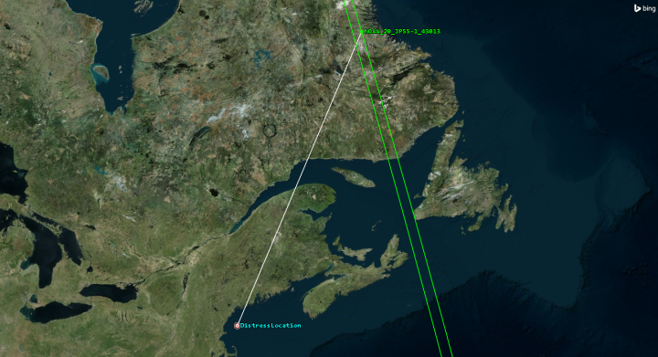
Distress location ACCESS to a NOAA satellite
Confirming the distress call
Due to the large number of false alarms received by the NOAA satellites, a rescue response is initiated only after a second satellite pass confirms the distress signal.
Creating a new Interval
A time
- Right-click on DistressCall () in the Object Browser.
- Select Analysis Workbench... (
 ) in the shortcut menu.
 - Select the Time tab when the Analysis Workbench opens.
- Click Create new Interval (
 ) in the Time Tool toolbar.
Using the Interval From List component type
The Interval From List component type is a single interval created from an Interval List and is defined by a specified Interval List component.
- Keep the default Interval From List as the Type when the Add Time Component dialog box opens.
- Enter DistressConfirmed in the Name field.
- Click the Interval List ellipsis ().
- Select DistressCall () in the object list when the Select Reference Interval List dialog box opens.
- Select CompleteChainAccessIntervals (
 ) in the Interval Lists for: DistressCall list.
 - Click to close the Select Reference Interval List dialog box.
Adding the second satellite pass
The distress call is confirmed by the second satellite pass. When the access displays on the Timeline View in the DistressConfirmed row, you will know that the second satellite has confirmed the distress call.
- Open the Interval Selection drop-down list when you return to the Add Time Component dialog box.
- Select Count forward from Start.
- Enter 2 in the Interval Number field.
- Click to close the Add Time Component dialog box.
- Click and drag DistressConfirmed () from the Components for: DistressCall list to the Timeline View's Time Display.
- Keep the Analysis Workbench open.
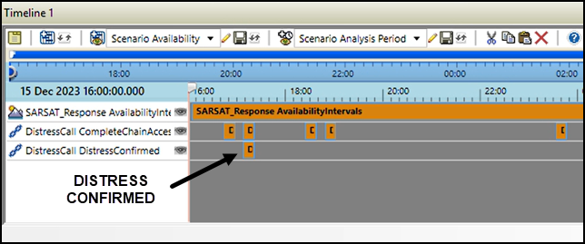
Distress call Confirmed
Inserting the helicopter's preparation time
Once the distress signal is confirmed, it takes time to contact the rescue station and for them to prepare and dispatch a rescue helicopter.
Creating a new Time Instant
A
- Return to the Time Tool.
- Select DistressCall () in the object tree.
- Click Create new Time Instant (
 ) in the Time Tool toolbar.
 - Click Type: when the Add Time Component dialog box opens.
Using the Fixed Time Offset component type
The Fixed Time Offset component type is a time instant offset by a fixed time relative to another time instant component.
- Select Fixed Time Offset () in the Select Component Type list when the Select Component Type dialog box opens.
- Click to close the Select Component Type dialog box.
- Enter Rescue Launch Time in the Name field when you return to the Add Time Component dialog box.
- Click the Reference Time Instant ellipsis ().
- Select DistressCall () in the object list when the Select Reference Time Instant dialog box opens.
- Expand (
 ) DistressConfirmed (
 ) in the Time Instants for: DistressCall list.
 - Select Stop (
 ).
). - Click to close the Select Reference Time Instant dialog box.
Setting the rescue launch time
The rescue launch time begins 20 minutes after the distress confirmed time. Add the Rescue_Launch_Time Time Instant to the Time Display.
- Enter 20 min in the Time Offset field when you return to the Add Time Component dialog box.
- Click to close the Add Time Component dialog box.
- Click and drag Rescue_Launch_Time () from the My Components (
 ) folder to the Timeline View's Time Display.
 - Keep the Analysis Workbench open.
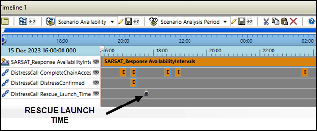
Rescue launch time
Creating the Coast Guard Air Station
The rescue helicopter will launch from U.S. Coast Guard Air Station Cape Cod, which is the only Coast Guard Aviation facility in the northeastern United States, and fly to the distress location.
- Insert a Place (
 ) object using the Insert Default () method.
 - Rename Place1 () Coast_Guard_Air_Station_Cape_Cod_MA.
- Open Coast_Guard_Air_Station_Cape_Cod_MA's () Properties ().
- Select the Basic - Position page when the Properties Browser opens.
- Enter the following in the Position panel:
- Click to accept your changes and to close the Properties Browser.
| Option | Value |
|---|---|
| Latitude | 41.66541 deg |
| Longitude | -70.52475 deg |
Modeling the rescue helicopter's mission
The Coast Guard station operates MH-60 Jayhawk rescue helicopters. Model the rescue helicopter and its flight route.
Inserting an Aircraft object
Insert a new
- Insert an Aircraft (
 ) object using the Insert Default () method.
 - Rename Aircraft1 () RescueHelicopter.
Using the Great Arc propagator
The Great Arc Propagator defines the route of an aircraft that follows a point-by-point path over the surface of the Earth at a given altitude.
- Open RescueHelicopter's () Properties ().
- Select the Basic - Route page when the Properties Browser opens.
Using a Time Instant as the Start Time
You can change the takeoff time of your helicopter by using the Rescue_Launch_Time Time Instant component you created.
- Open (
 ) the Start Stop drop-down menu.
 - Select Start Time in the drop-down menu.
- Select Time Component... in the Start Time submenu.
- Select DistressCall () in the object list when the Select Time Instance dialog box opens.
- Select Rescue_Launch_Time (
 ) in the Time Instants for: DistressCall list.
 - Click to close the Select Time Instance dialog box.
- Click to accept you change and to keep the Properties Browser open.
Creating the helicopter's route waypoints
The helicopter will take off from the Coast Guard Base, fly north along the coast, and then turn towards the distress location.
- Click to create your first waypoint.
- Enter the following values for waypoint one:
- Click .
- Enter the following values for the second waypoint:
- Click .
- Enter the following values for the third waypoint:
- Click to accept your changes and to keep the Properties Browser open.
| Option | Value |
|---|---|
| Latitude | 41.66541 deg |
| Longitude | -70.52475 deg |
| Altitude | 1000 ft |
| Speed | 160 mi/hr |
| Option | Value |
|---|---|
| Latitude | 42.6 deg |
| Longitude | -70.5 deg |
| Turn Radius | 500 ft |
| Option | Value |
|---|---|
| Latitude | 43 deg |
| Longitude | -70 deg |
| Altitude | 100 ft |
| Speed | 10 mi/hr |
Now the helicopter, instead of launching at the start of the scenario (default), will launch 20 minutes after the confirmation of the distress call. Furthermore, since the launch time depends on the distress call intervals, if those intervals change, the launch time will automatically update.
Changing the Aircraft object's model
You will use a more realistic model for your helicopter and change its appearance in your scenario.
- Select the 3D Graphics - Model page.
- Click the Model File ellipsis () in the Model panel.
- Select sh-60_seahawk.glb in the File dialog box.
- Click .
- Click to accept your changes and to close the Properties Browser.
The MH-60 Jayhawk is based on the SH-60 Seahawk helicopter.
Viewing the rescue helicopter's flight route
View thee Rescue Helicopter's flight route in the 3D Graphics window.
- Select the Basic - Route page.
- Copy the time from the second waypoint.
- Paste the time in the Current Scenario Time field of the Animation toolbar.
- Select the Enter key.
- Click to close the Properties Browser.
- Bring the 3D Graphics window to the front.
- Zoom to RescueHelicopter ().
- Zoom out until you can see RescueHelicopter's () flight route.
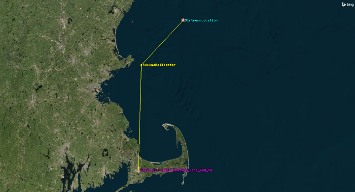
Rescue helicopter flight route
Adding the helicopter's flight time
Add the Interval of the helicopter's flight to the Timeline View.
- Return to the Analysis Workbench.
- Select the Time tab.
- Select RescueHelicopter () in the object tree.
- Click and drag EphemerisTimeSpan (
 ) from the Installed Components () folder to the Timeline View.
 - Keep the Analysis Workbench open.
Rescue Helicopter's flight time
Showing position updates
Create a new Interval List to determine when the rescue helicopter might receive updates on the position of the distress location as it approaches. Updates are received when a NOAA satellite accesses DistressLocation. This is accomplished by merging the DistressCall Complete Chain Access intervals with the RescueHelicopter's Ephemeris Time Span interval.
Creating a new Interval List
An
- Return to the Analysis Workbench.
- Select the Time tab.
- Select DistressCall () in the object list.
- Click Create new Interval List (
 ) in the Time Tool toolbar.
Using the Merged Interval List type
A Merged Interval List component type contains intervals merged from multiple intervals or Interval List Time Components using one of several merging operations.
- Click Type: when the Add Time Component dialog box opens.
- Select Merged () in the Select Component Type list when the Select Component Type dialog box opens.
- Click to close the Select Component Type dialog box.
- Enter Distress Position Updates in the Name field when you return to the Add Time Component dialog box.
- Make sure the default AND value is showing in the Operation field.
- Select the first time component in the Time Components list.
- Click .
- Select the second time component in the Time Components list.
- Click .
Adding DistressCall to the Time Components list
Add DistressCall's Complete Chain Access intervals to the Time Components List.
- Click .
- Select DistressCall () in the object list when the Select Time Intervals dialog box opens.
- Select CompleteChainAccessIntervals () in the Components for: DistressCall list.
- Click to close the Select Time Intervals dialog box.
Adding RescueHelicopter's ephemeris time span to the Time Components list
Add the rescue helicopter's Ephemeris Time Span interval to the Time Components list.
- Click .
- Select RescueHelicopter () in the object list when the Select Time Intervals dialog box opens.
- Select EphemerisTimeSpan (
 ) in the Components for: RescueHelicopter list.
 - Click to close the Select Time Intervals dialog box.
- Click to close the Add Time Component dialog box.
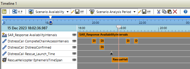
Adding the Distress Position Updates to the Timeline View
With your Merged Interval List created, add it to the Timeline View.
- Click and drag Distress_Position_Updates () from the My Components () folder to the Timeline View's Time Display.
- Click to close the Analysis Workbench.
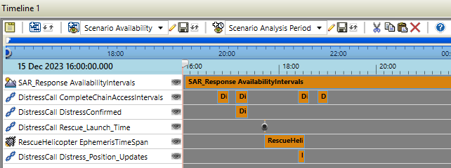
Distress position updates
You can see that the rescue helicopter receives an update about the distress position's location as it approaches the distress site.
Reviewing the system response time
Use the Time Display to see just how long it takes from the time the distress call is confirmed to the time that the rescue helicopter reaches the distress location. The Coast Guard aims for no greater than a two-hour total response time, calculated from the time of notification of the Coast Guard until the time of arrival on scene, including the preparation time.
- Right-click on DistressCall DistressConfirmed time component interval.
- Select Set Animation Time to Interval Stop Time in the shortcut menu.
- Note the time in the Animation Toolbar.
- Right-click on the RescueHelicopter EphemerisTimeSpan time component interval.
- Select Set Animation Time to Interval Stop Time in the shortcut menu.
- Note the time in the Animation Toolbar.
You can see then that the help arrives approximately one and a quarter hours after the Coast Guard was notified and approximately two and a half hours after the beacon was first activated.
Saving your work
Clean up your workspace and close out your scenario.
- Close all reports and windows except the 2D and 3D Graphics windows.
- Save () your work.
- Close the scenario when finished.
Summary
You practiced using the Timeline View and the Time tool in Analysis Workbench to interact with your scenario. You used Time components to set access constraints and from timeline intervals for your reports or graphs. You set your object behaviors and display properties with Time components and used the Timeline View to evaluate the total system response time.
On your own
In order for the rescue helicopter to receive updates on the position of the distress location as it approaches, the route needs to overlap with at least one of the Complete Chain Access intervals. You can relocate the distress location and modify the rescue helicopter's route so they overlap allowing time for the helicopter to get distress position updates. This will then display Distress_Position_Updates intervals. All the time components that you created will automatically update.