STK Premium (Space) or STK Enterprise
You can obtain the necessary licenses for this tutorial by contacting AGI Support at support@agi.com or 1-800-924-7244.
The results of the tutorial may vary depending on the user settings and data enabled (online operations, terrain server, dynamic Earth data, etc.). It is acceptable to have different results.
Capabilities covered
This lesson covers the following capabilities of the Ansys Systems Tool Kit® (STK®) digital mission engineering software:
- STK Pro
- Astrogator
Problem statement
You have a satellite in a near-circular, equatorial orbit. You want to raise the apogee, and then the perigee.
Solution
Use the STK/Astrogator® capability to model the satellite and raise its apogee and perigee using an Automatic Sequence. You will perform a 100-meter-per-second burn at every perigee until the apogee altitude is greater than 10,000 kilometers. After that, you will perform a 100-meter-per-second burn along the velocity vector at apogee until the perigee altitude is greater than 10,000 kilometers.
What you will learn
Upon completion of this tutorial, you will be able to:
- Open and design Automatic Sequences
- Set and configure user-defined stopping conditions
- Create and generate custom graphs
Video guidance
Watch the following video. Then follow the steps below, which incorporate the systems and missions you work on (sample inputs provided).
Creating a new scenario
First, you must create a new STK scenario, and then build from there.
- Launch the STK application (
 ).
). - Click
 Create a Scenario when the Welcome to STK dialog box opens.
 - Enter the following in the STK: New Scenario Wizard:
- Click when you finish.
- Click Save (
 ) when the scenario loads. The STK application creates a folder with the same name as your scenario for you.
 - Verify the scenario name and location in the Save As dialog box.
- Click .
| Option | Value |
|---|---|
| Name | PulsedOrbitRaise |
| Location | Default |
| Start | Default |
| Stop | + 2 days |
Save (![]() ) often during this lesson!
) often during this lesson!
Configuring an Astrogator satellite
The Astrogator capability contains specialized analysis for interactive orbit maneuver and spacecraft trajectory design. Astrogator calculates the satellite's ephemeris by running a Mission Control Sequence, or MCS, that you define according to the requirements of your mission.
Astrogator enables you to model impulsive and finite maneuvers as well as high-fidelity orbit propagation. It provides targeting methods, including:
- A differential corrector used to find the necessary values of control parameters (such as launch epoch or burn duration) to meet desired mission goals.
- An optimizer used to change control parameters to achieve a goal, while applying a set of constraints that define the problem space.
Furthermore, Astrogator allows you to define automatic sequences. These represent predefined sets of actions that can be performed whenever a specified event occurs, such as a maneuver that occurs at every periapsis. These details highlight just some of Astrogator's many features.
Astrogator also utilizes a component catalog and editor in the STK application called the Component Browser. The
Inserting a Satellite object
Start by inserting a Satellite object into the scenario.
- Bring the Insert STK Objects tool (
 ) to the front.
 - Select Satellite (
 ) in the Select An Object To Be Inserted list.
 - Select Insert Default () in the Select A Method list.
- Click .
- Right-click on Satellite1 () in the Object Browser.
- Select Rename in the shortcut menu.
- Rename Satellite1 () TransferSat.
Changing the propagator to Astrogator
Change the satellite's propagator to Astrogator.
- Right-click on TransferSat () in the Object Browser.
- Select Properties (
 ) in the shortcut menu.
 - Select the Basic - Orbit page when the Properties Browser opens.
- Open the Propagator drop-down list.
- Select Astrogator.
- Click to confirm your change and to keep the Properties Browser open.
Configuring the Initial State segment
Use the
- Select Initial State (
 ) in the Mission Control Sequence (MCS).
 - Select the Elements tab.
- Open the Coordinate Type drop-down list.
- Select Keplerian.
- Set the following Keplerian values:
- Keep the remaining default values.
- Click to confirm your changes and to keep the Properties Browser open.
| Option | Value |
|---|---|
| Semi-major Axis | 7000 km |
| Eccentricity | 0.001 |
| Inclination | 0 deg |
Creating and designing an Automatic Sequence
Automatic Sequences are MCS elements that are structurally similar to Sequence segments, but are not MCS segments, properly. Rather, Automatic Sequences can be assigned to Propagate and (finite) Maneuver segments, and function as subroutines, which execute in response to specified stopping conditions of those segments.
Creating a new Automatic Sequence
Create a new Automatic Sequence in the MCS toolbar.
- Click Automatic Sequence Browser (
 ) in the MCS toolbar.
 - Click when the Automatic Sequence Browser opens.
- Enter Small Burn in the Name field of the Field Editor dialog box.
- Click to confirm your change and to close the Field Editor dialog box.
You will notice that the Stop sequence is the only one available by default. It is called any time a Stopping Condition in the Propagate segment is matched.
Editing the Automatic Sequence
You want the Automatic Sequence to run when well-defined circumstances occur.
- Select Small Burn in the Automatic Sequence Browser.
- Click .
- Click Insert Segment After (
 ) in the MCS toolbar of the Automatic Sequence Properties dialog box.
 - Select Maneuver (
 ) in the Segment Selection dialog box.
 - Click to confirm your selection and to close the Segment Selection dialog box.
- Note that the Maneuver Type defaults to Impulsive.
For an
Setting the Maneuver segment's attitude
The Attitude Control field enables you to select the mode in which the maneuver pointing direction is prescribed. When using Attitude Control - Along Velocity Vector, the satellite object’s attitude is such that the Delta-V vector aligns with the spacecraft's inertial velocity vector. The inertial reference frame depends on the central body of the satellite object. Either the thruster set or an engine model defines the Delta-V in the body frame. Delta-V Magnitude is the magnitude of the impulse to be added to the spacecraft velocity vector in distance / time.
- Select the Attitude tab.
- Note the Attitude Control defaults to Along Velocity Vector
- Enter 100 m/sec in the Delta-V Magnitude field.
- Click to confirm your changes and to close the Automatic Sequence Properties dialog box.
- Click to confirm your changes and to close the Automatic Sequence Browser.
- Click to confirm your changes and to keep the Properties Browser open.
Renaming the Propagate segment
Rename the default Propagate segment.
- Right-click on Propagate (
 ) in the MCS.
 - Select Rename in the shortcut menu.
- Rename Propagate () Raise Apogee.
Creating and configuring a stopping condition
Use the Propagate segment to model the movement of the spacecraft along its current trajectory until meeting a specified stopping condition. The segment uses the defined propagator and integrator to propagate the state, adding each point to the ephemeris as it goes.
After each step, the segment checks to see if any stopping conditions were met during the step. If so, it then finds the exact point, within tolerance, where the stopping condition is satisfied. From that point, the segment either executes an automatic sequence or stops the propagation and passes the state at that point to the next segment. Astrogator also adds an ephemeris point at the time that the stopping condition is triggered.
- Ensure the Trip value for the Duration Stopping Condition is set to 43200 sec (which is equivalent to 0.5 day) in the Stopping Conditions panel.
- Click New... () on the Stopping Conditions panel toolbar.
- Select Periapsis (
 ) in the New Stopping Condition dialog box.
 - Click to confirm your selection and to close the New Stopping Condition dialog box.
Using the automatic sequence
You will trigger the Small Burn automatic sequence when the Periapsis stopping condition is met.
- Click the Sequence ellipsis (
 ) in the Stopping Conditions panel.
 - Select Small Burn (
 ) in the Select Component dialog box.
 - Click to confirm your selection and to close the Select Component dialog box.
- Enter 2 in the Max Trip Times field.
- Click to confirm your changes and to keep the Properties Browser open.
When the Periapsis stopping condition is met, instead of stopping the propagation and passing the control to the next segment, the Periapsis stopping condition automatically starts the Small Burn sequence. After the maneuver is executed, the control is passed back to the Raise Apogee Propagate segment that propagates the orbit to the next stopping condition, which again is Periapsis. The maneuver is executed for the second and last time, since the Max Trip Times field is set to 2. The control is passed back to the Propagate segment for the remainder of the propagation duration.
Running the Mission Control Sequence
To calculate the trajectory of the spacecraft you must run the Mission Control Sequence. Astrogator will proceed through the MCS and run each segment, generating an ephemeris for the spacecraft. As it runs the MCS, Astrogator carries the trajectory and state of the spacecraft determined so far from one segment to the next.
- Click Run Entire Mission Control Sequence (
 ) in the MCS toolbar.
 - Save () the scenario.
Since the periapsis condition has been met twice, the Propagate segment no longer stops the propagation at periapsis; instead, it is stopped when the duration of a half day is met.
Generating a Maneuver Summary report
Verify the results with a Maneuver Summary report.
- Right-click on TransferSat () in the Object Browser.
- Select Report & Graph Manager... (
 ) in the shortcut menu.
 - Select the Maneuver Summary (
 ) report in the Installed Styles (
 ) folder when the Report & Graph Manager opens.
 - Click .
- Leave the Maneuver Summary report open.
A Maneuver Summary report is a great place to verify the MCS run when there are multiple burns, especially if they are executed from within Automatic Sequences. The segment column is useful to see which segment fired the maneuver and the Total Fuel Used is useful for fuel budget information.
Adding a constraint for the apogee radius
Instead of limiting the number of Small Burn maneuvers to execute, you can allow Astrogator to continue the Raise Apogee segment until a certain threshold is met. You can do this by adding a new stopping condition with a constraint to check when you reach an apogee of 10,000 kilometers or greater.
Updating the Periapsis stopping condition
Update the Periapsis stopping condition to remove the Duration stopping condition and increase the Max Trip Times to its original default value.
- Return to TransferSat's () Properties ().
- Select Raise_Apogee () in the MCS.
- Select the Periapsis stopping condition in the Stopping Conditions panel.
- Enter 1000 in the Max Trip Times field.
- Select the Duration stopping condition.
- Click Delete (
 ) in the Stopping Conditions panel toolbar.
Adding an apoapsis stopping condition
You need to stop the sequence just when the apoapsis radius is greater than 10,000 kilometers. You can do this by adding a constraint.
- Click New... () on the Stopping Conditions panel toolbar.
- Select Apoapsis () in the New Stopping Condition dialog box.
- Click to confirm your selection and to close the New Stopping Condition dialog box.
Adding a new constraint component
Add a user-defined trigger for determining whether your stopping condition has been satisfied with a new constraint component.
- Click the Constraints panel ellipsis ().
- Select UserDefined () in the Select Constraints dialog box.
- Click Insert Component (
 ).
).
Renaming the constraint
Update the name of the constraint.
- Double-click on the ComponentName entry in the Component Details list.
- Enter Apoapsis GT 10000 in the String Value field in the String Field dialog box.
- Click to confirm your change and to close the String Field dialog box.
Selecting the stopping criteria
Configure the stopping condition so that the test parameter must be greater than a stated value.
- Double-click on the Criteria entry.
- Open the Selection drop-down list in the Listbox Field dialog box.
- Select Greater Than.
- Click to confirm your selection and to close the Listbox Field dialog box.
Changing the calculation object
Replace the default calculation object with a Radius of Apoapsis object from the Component Browser.
- Double-click on the CalcObject entry.
- Click the Component ellipsis () in the Embedded Component Link Selection dialog box.
- Expand (
 ) Keplerian Elems in the Select Component dialog box.
 - Select Radius Of Apoapsis ().
- Click to confirm your selection and to close the Select Component dialog box.
- Click to confirm your change and to close the Embedded Component Link Selection dialog box.
Specifying the constraint's target value
Specify the target value for the constraint.
- Double-click on the Value entry.
- Enter 10000 km in the Real field in the Real Number Field dialog box.
- Click to confirm your change and to close the Real Number Field dialog box.
- The Component Details list should look like the following:
- Click to confirm your changes and to close the Select Constraints dialog box.
- Click to confirm your changes and to keep the Properties Browser open.
| Option | Value |
|---|---|
| ComponentName | Apoapsis_GT_10000 |
| Criteria | Greater Than |
| CalcObject | Radius_Of_Apoapsis |
| UseAbsoluteValue | False |
| Value | 10000 km |
Re-running the Mission Control Sequence
With your constraint defined, run the MCS.
- Click Run Entire Mission Control Sequence () in the MCS toolbar.
- Save () the scenario.
Refreshing the Maneuver Summary Report
Refresh the Maneuver Summary Report to see changes using the new stopping conditions.
- Return to the Maneuver Summary report
- Click Refresh (F5) (
 ) in the Maneuver Summary Report toolbar.
 - Note that the number of maneuvers has increased.
- Close the Maneuver Summary Report.
Creating a custom graph of the apogee radius
You can create a new graph style that will graph the radius of apogee.
Creating a new graph style
Create a new graph style to chart the satellite's apogee radius.
- Return to the Report & Graph Manager ().
- Select the My Styles () folder.
- Click Create new graph style (
 ) in the Styles panel toolbar.
 - Name the new graph (
 ) Apo Peri Graph.
 - Select the Enter key to set the name and to open the custom report's Properties ().
Selecting the data provider, group and elements
You will use the Classical Elements data provider which contains classical osculating orbital elements, sometimes referred to as Keplerian elements, computed using ephemeris with respect to the object's central body, as observed from the requested coordinate system, as a function of time.
- Select the Content page when the Property Browser opens.
- Expand () Classical Elements () data provider in the Data Provider list.
- Expand () the ICRF () data provider group.
- Select the Apogee Radius (
 ) data provider element.
 - Click Insert Y Axis () in the Y Axis panel.
- Click to confirm your selection and to close the Property Browser.
Generating the custom graph
With your data provider selected, generate the graph.
- Select Apo Peri Graph () in the My Styles () folder.
- Click .
- An apogee is reached. If the apogee radius is greater than 10,000 kilometers, control is passed onto the next segment in the MCS. Otherwise, nothing happens and the control is sent back the propagator.
- A perigee is reached. In this case, the Automatic Sequence is fired and the control is sent back to the propagator.
- Close the Apo Peri Graph ().
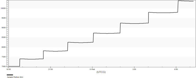
Apogee Radius graph
The Raise Apogee segment propagates until:
Raising the perigee with constraints
You want to raise the satellite's perigee up to a minimum radius of 10,000 kilometers. To accomplish this, you will create a new Propagate segment with similar logic to the Raise Apogee segment.
Inserting a new Propagate segment
Add a new Propagate segment at the end of TransferSat's MCS.
- Return to TransferSat's () Properties ().
- Right-click on the Return Segment (
 ) in the MCS.
 - Select Insert Before... in the shortcut menu.
- Select Propagate () in the Segment Selection dialog box.
- Click to confirm your selection and to close the Segment Selection dialog box.
Updating the Propagate segment's properties
Change the name and the color of the new Propagate segment.
- Select Propagate () in the MCS.
- Click Segment Properties () in the MCS toolbar.
- Enter Raise Perigee in the Name field in the Edit Segment dialog box.
- Open the Color drop-down list.
- Select a color that's different from Raise_Apogee (), such as Red.
- Click to confirm your changes and to close the Edit Segment dialog box.
- Click to confirm your changes and to keep the Properties Browser open.
Inserting an Apoapsis stopping condition
To raise the perigee, you need to burn at apogee. You can use the Small Burn sequence previously defined as the triggered event.
- Click New... () in the Stopping Conditions panel toolbar.
- Select Apoapsis () in the New Stopping Condition dialog box.
- Click to confirm your selection and to close the New Stopping Condition dialog box.
Setting the sequence
Trigger the Small Burn Automatic Sequence to fire when the Apopapsis stopping condition is met.
- Click the Sequence ellipsis ().
- Select Small Burn () in the Select Component dialog box.
- Click to confirm your selection and to close the Select Component dialog box.
- Select Duration in the Stopping Conditions list.
- Click Delete () in the Stopping Conditions panel toolbar.
- Click to confirm your changes and to keep the Properties Browser open.
Inserting a Periapsis stopping condition
You want to stop the propagation only when the perigee radius is greater than 10,000 kilometers. You can add that as a constraint.
- Click New... () in the Stopping Conditions panel toolbar.
- Select Periapsis () in the New Stopping Condition dialog box.
- Click to confirm your selection and to close the New Stopping Condition dialog box.
Adding a new constraint component
Add a constraint to the Periapsis stopping condition.
- Click the Constraints panel ellipsis ().
- Select UserDefined () in the Select Constraints dialog box.
- Click Insert Component ().
Changing the component name
Update the constraint component's name.
- Double-click on the ComponentName entry in the Component Details list
- Enter Periapsis GT 10000 in the String Value field in the String Field dialog box.
- Click to confirm your change and to close the String Field dialog box.
Selecting the criteria
Configure the stopping condition so that the test parameter will be satisfied when it is greater than a stated value.
- Double-click on the Criteria entry.
- Open the Selection drop-down list in the Listbox Field dialog box.
- Select Greater Than.
- Click to confirm your selection and to close the Listbox Field dialog box.
Selecting the calculation object
Use the radius of periapsis as the calculation object for the constraint.
- Double-click on CalcObject.
- Click the Component ellipsis () in the Embedded Component Link Selection dialog box.
- Expand () Keplerian Elems in the Select Component dialog box.
- Select Radius Of Periapsis ().
- Click to confirm your selection and to close the Select Component dialog box.
- Click to confirm your change and to close the Embedded Component Link Selection dialog box.
Changing the value
Set the target value for Radius Of Periapsis calculation to 10,000 km.
- Double-click on the Value entry.
- Enter 10000 km in the Real field in the Real Number Field dialog box.
- Click to confirm your change and to close the Real Number Field dialog box.
- Click to confirm your changes and to close the Select Constraints dialog box.
- Click to confirm your changes and to keep the Properties Browser open.
Running the Entire Mission Control Sequence
With your new Propagate segment configured, run the entire mission control sequence.
- Click Run Entire Mission Control Sequence () in the MCS toolbar.
- Bring the 3D Graphics window to the front.
- Use your mouse to obtain a view of TransferSat's () orbit.
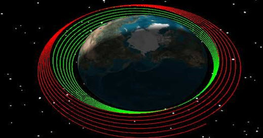
TransferSat's Orbit
Adding the perigee radius to the custom graph
Add the radius of perigee to the custom graph you created earlier to view the effects of your orbit-raising strategy.
Updating the Apo Peri Graph's properties
Open Apo Peri Graph's properties to add the additional data provider element.
- Return to the Report & Graph Manager ().
- Right-click on Apo Peri Graph () in the My Styles () folder.
- Select Properties () in the shortcut menu.
- Select the Content page when the Properties Browser opens.
Selecting a second data provider element
Add the Perigee Radius data provider element to your graph.
- Expand () the Classical Elements () data provider.
- Expand () the ICRF () data provider group.
- Select the Perigee Radius () data provider element.
- Click Insert Y Axis () in the Y Axis panel.
- Click to confirm your selection and to close the Property Browser.
Generating the updated custom graph
With the perigee radius now added, generate your custom Apo Peri graph.
- Select Apo Peri Graph () in the My Styles () folder.
- Click .
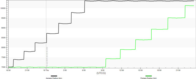
Apogee and Perigee Radius graph
After the Raise Apogee Propagation segment is finished, the Raise Perigee Propagate segment runs until the Perigee is above 10,000 kilometers.
Saving your work
Clean up and close out your scenario.
- Close any open reports, properties, and the Report & Graph Manager.
- Save () your work.
Summary
You created a Satellite object in an initial orbit. Using an Automatic Sequence to trigger a 100-meter-per-second burn, you raised the satellite's apogee in a transfer orbit by limiting the number of trips and the duration of time between which the maneuver could be performed. You then modified your orbit-raising strategy by setting user-defined stopping conditions and constraining the stopping conditions to trigger the Automatic Sequence, which performed a 100-meter-per-second burn at every perigee until the apogee altitude was greater than 10,000 kilometers. After that, you used the same Automatic Sequence in another segment with different stopping conditions and constraints to perform 100-meter-per-second burns along the velocity vector at apogee until the perigee altitude was greater than 10,000 kilometers.