Introduction to Multifunction Radar
STK Pro, STK Premium (Air), STK Premium (Space), or STK Enterprise
You can obtain the necessary licenses for this tutorial by contacting AGI Support at support@agi.com or 1-800-924-7244.
The results of the tutorial may vary depending on the user settings and data enabled (online operations, terrain server, dynamic Earth data, etc.). It is acceptable to have different results.
Capabilities covered
This lesson covers the following STK Capabilities:
- STK Pro
- Radar
Problem statement
You need a new multifunction radar (MFR) system with multiple waveforms for tracking, spinning volume search, and fixed horizon search. If you are an engineer or operator charged with designing or purchasing this system, you would want the ability to simulate those radar systems beforehand. How do you do that?
Solution
You can use the STK Radar capability to simulate a multifunction radar (MFR) system. You can even visualize the multiple waveforms for tracking, spinning volume search, and fixed horizon search.
What you will learn
STK Multifunction radar models multiple radar beams and the simultaneous handling of tasks by them. For example, you can model beams that follow a schedule to carry out tasks, assign beams to scan search zones or track targets, or apply multiple waveform strategies while tracking a target.
When you complete this tutorial, you will be able to:
- Employ the Multifunction Radar user interface
- Design a multibeam system
- Implement tasking by time intervals
- Create and assign waveform strategies
- Set up polarization
- Create reports and graphs of data providers
Video Guidance
Watch the following video. Then follow the steps below, which incorporate the systems and missions you work on (sample inputs provided).
Creating a new scenario
First, you must create a new STK scenario; then build from there.
- Launch STK (
 ).
). - Click Create a Scenario (
 ) in the Welcome to STK dialog box.
 - Enter the following in the STK: New Scenario Wizard:
- Click when you finish.
- Click Save (
 ) after the scenario loads. STK creates a folder with the same name as your scenario for you.
 - Verify the scenario name and location in the Save As window.
- Click .
| Option | Value |
|---|---|
| Name | STK_MFR |
| Start | 26 Apr 2023 18:00:00.000 UTCG |
| Stop | + 1 hr |
Save (![]() ) often during this lesson!
) often during this lesson!
Cleaning up the 3D Graphics window
Since you're using terrain in the 3D Graphics window, it's a good idea to use the Label Declutter option for the 3D Graphics window. This option moves the labels away from the central body and toward the viewer, which prevents the labels from being obscured by the terrain.
- Bring the 3D Graphics window to the front.
- Click Properties (
 ) in the 3D Window toolbar.
 - Select the Details page.
- Select the Enable check box in the Label Declutter panel.
- Click to apply the changes and dismiss the Properties Browser.
Creating the radar site as a Place object
Before you can make a multifunction radar system, you need to set the location of the radar system and then some aircraft for it to track. This multifunction radar is located near a regional airport. You can use the Place (![]() ) object as a base for the Radar (
) object as a base for the Radar (![]() ) object.
) object.
- Select Place (
 ) in the Insert STK Objects tool.
 - Select the Define Properties () method.
- Click .
- Set the following when the Properties Browser opens:
- Click to apply the changes and dismiss the Properties Browser.
- Right-click Place1 () in the Object Browser.
- Select Rename in the shortcut menu.
- Rename Place1 () to Radar_Site.
| Option | Value |
|---|---|
| Latitude | 34.7422 |
| Longitude | -118.225 |
| Height Above Ground | 50 ft |
The radar antenna is 50 feet above the ground. When you elevate the Place (![]() ) object 50 feet, any attached objects are also at that altitude.
) object 50 feet, any attached objects are also at that altitude.
Viewing the radar site in 3D
Zoom to the radar site for situational awareness.
- Bring the 3D Graphics window to the front.
- Right-click Radar_Site () in the Object Browser.
- Select Zoom To.
- Use your mouse to view the radar site and surrounding territory.
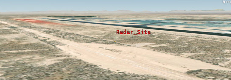
Radar Site
Adding a large civilian airliner
Model a civilian airliner that is flying through the regional airport's zone from south to north.
- Insert an Aircraft (
 ) object using the Define Properties () method.
 - Select the Basic - Route page when the Properties Browser opens.
- Open the Reference drop-down menu in the Altitude Reference panel.
- Select MSL.
- Click .
- Set the following for waypoint one:
- Click .
- Set the following for waypoint two:
- Click to apply the changes and keep the Properties Browser open.
| Option | Value |
|---|---|
| Latitude | 33.0 deg |
| Longitude | -118.0 deg |
| Option | Value |
|---|---|
| Latitude | 37.0 deg |
| Longitude | -118.0 deg |
Specifying the airliner radar cross section
Radar cross section (RCS) is an important property of any potential radar target. With STK's Radar capability, you can specify the RCS of a potential target before you set up and constrain a radar system.
- Select the RF - Radar Cross Section page.
- Clear the Inherit check box. This enables you to set an individual RCS value that overrides the scenario-level RCS value.
- Enter 20 dBsm in the Constant RCS Value field in the Band Properties panel. This value is typical of a large civilian airliner.
- Click to apply the changes and dismiss the Properties Browser.
- Rename Aircraft1 () to Airliner.
Viewing the airliner in 3D
- Zoom to Airliner ().
- Select the 3D Graphics window. You can see the Airliner with the radar site in the distance.
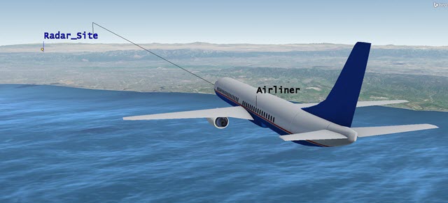
Airliner and Radar Site
Adding a small private aircraft
Model a small, single-engine aircraft that is flying in from east to west toward the local airfield.
- Insert an Aircraft () object using the Define Properties method ().
- Select the Basic - Route page.
- Set Reference to MSL.
- Click .
- Set the following for waypoint one:
- Click .
- Set the following for waypoint two:
- Click to apply the changes and keep the Properties Browser open.
| Option | Value |
|---|---|
| Latitude | 34.75 deg |
| Longitude | -117.50 deg |
| Altitude | 5000 ft |
| Speed | 140 mi/hr |
| Option | Value |
|---|---|
| Latitude | 34.75 deg |
| Longitude | -119.0 deg |
Changing the object's 3D graphics model
To improve the realism of the 3D Graphics view of this aircraft, change the model of the private plane.
- Select the 3D Graphics - Model page.
- Click the Model File ellipsis (
 ) in the model panel.
 - Select single_engine.glb in the File dialog box.
- Click .
- Click to apply the changes and keep the Properties Browser open.
Specifying the small private aircraft radar cross section
The private, single-engine aircraft has a much smaller RCS than the airliner.
- Select the RF - Radar Cross Section page.
- Clear the Inherit check box.
- Set Constant RCS Value to 10 dBsm. This value is typical of a popular, single-engine aircraft.
- Click to apply the changes and dismiss the Properties Browser.
- Rename Aircraft2 () to PrivatePlane.
Viewing the small private aircraft in 3D
- Zoom to PrivatePlane ().
- Bring the 3D Graphics window to the front. You can see the private plane and the radar site in the distance.
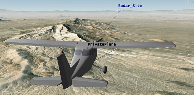
Private Plane and Radar Site
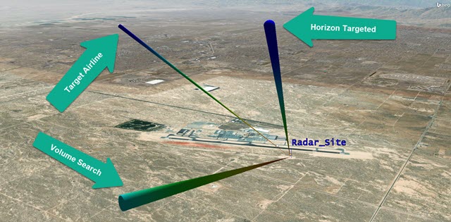
Establishing your multifunction radar system
The multifunction radar could have many antennas performing different tasks. To define your STK Multifunction Radar, you'll break it down to four beams.
- Beam 1 (Target Airliner) locks onto and tracks the airliner.
- Beam 2 (Volume Search) spins and scans the horizon.
- Beam 3 (Horizon Search) is fixed and scans in one direction.
- Beam 4 (Horizon Targeted) simulates Beam 3 switching from a fixed-search pattern to tracking the private plane.
If an aircraft flies through the fixed beam (Beam 3, Horizon Search), your search and track data should have a small fluctuation. The exact size of the fluctuation depends on the size and speed of the aircraft. Such fluctuations are reflected in the signal-to-noise ratio (SNR) and the probability of detection (PDET) data providers. In response, Beam 3 shuts off and Beam 4 (which is exactly like Beam 3 except targeted) tracks the detected aircraft.
- Insert a Radar (
 ) object using the Insert Default () method.
 - Select Radar_Site () when the Select Object dialog box appears.
- Click .
- Rename Radar1 () to MFRadar.
Setting up the multifunction radar system
A multifunction radar models multiple radar beams working together at the same location. Each beam has its own power specifications and constraints.
- Right-click MFRadar () in the Object Browser.
- Select Properties ().
- Select the Basic - Definition page when the Properties Browser opens.
- Click the Radar System component selector ().
- Select Multifunction (
 ) in the Select Component dialog box.
 - Click to close the Select Component dialog box.
- Click to apply the changes and keep the Properties Browser open.
Specifying the beam orientation
All the beams created in this scenario are oriented along the Radar (![]() ) object's pointing type (fixed).
) object's pointing type (fixed).
- Select the Pointing tab.
- Ensure Pointing Type is set to Fixed Orientation.
- Ensure Orientation Method is set to Azimuth Elevation in the Fixed Orientation panel.
- Ensure Azimuth is 0 deg.
- Ensure Elevation is 90 deg.
When you design beams and set their individual azimuth and elevation values, they remain fixed relative to the Radar (![]() ) object.
) object.
Setting the radar transmitter power limit
Start by setting the multifunction radar's transmitter power limit. This is the peak output power of the transmitter.
- Select the Transmitter tab.
- Enter 40 dBW in the Max Power field.
- Click to apply the changes and keep the Properties Browser open.
Specifying the transmitter polarization
Polarization is a property of an electromagnetic wave. It describes the orientation of the electric field vector with reference to the antenna's orientation. The transmitter is linearly polarized with the electrical field aligned with the reference axis.
- Select the Polarization tab under the Transmitter tab.
- Select the Use check box.
- Select Linear from the drop-down menu.
- Click to apply the changes and keep the Properties Browser open.
Setting the radar receiver polarization
The receiver is linearly polarized with the electrical field aligned with the reference axis.
- Select the Receiver tab.
- Select the Polarization tab.
- Select the Use check box.
- Set the Polarization to Linear.
- Click to apply the changes and keep the Properties Browser open.
Adding gain
During communications and radar analysis, it is often necessary to model gains and losses that affect performance but are not defined using built-in analytical models. When the transmitted signal returns to the receiver, the system adds a separate gain to the signal.
- Select the Additional Gains and Losses tab under the Receiver tab.
- Click .
- Enter 10 dB in the Gain cell of the Pre-Receive Gains/Losses panel.
- Click to apply the changes and keep the Properties Browser open.
Configuring Beam 1 (Target Airliner beam)
For each of the four beams, you will generally follow this pattern:
-
You will configure the beam.
-
You will choose or create a waveform strategy for the beam.
-
You will visualize the beam in the 3D Graphics window.
-
You will create an Access report between the aircraft and the beam.
However, each beam has a unique purpose in the scenario and requires different settings as a result. Don't expect this pattern to be the exact same case for each beam. You can use the above pattern as a guide for understanding the basics of each beam and then compare how each beam is unique. For instance, the horizon beams (Beams 3 and 4) will use a time interval, unlike Beams 1 and 2. Beams 1 and 4 are both targeted beams.
With the workflow defined, configure the first beam. Beam 1 has a frequency of 2.9 GHz with a beam width of 1.4 degrees. This beam tracks the airliner with a power of 20 dBW and a 30 db Gain.
- Select the Beams tab.
- Double-click Beam001 in the BeamID cell.
- Rename Beam001 to Target Airliner.
- Select the Beam Spec tab within the Beams tab.
- Set the following options:
- Click to apply the changes and keep the Properties Browser open.
| Option | Value |
|---|---|
| BeamWidth | 1.4 deg |
| Gain | 30 dB |
Setting the pointing options for Beam 1 (Target Airliner)
You will set the beam to target the airliner.
- Select the Pointing tab.
- Open the Pointing Type drop-down menu.
- Select Targeted.
- Move (
 ) Airliner () from the Available Targets list to the Assigned Target list in the Targeted panel.
 - Click to apply the changes and keep the Properties Browser open.
Creating range-dependent waveform strategies for Beams 1 and 4
You can change the beam's frequency, power, or both by creating unique waveforms for that beam based on distance to the target. You can also define the pulse properties and number of pulses in the Radar Waveforms window. The Target Airliner beam will track the civilian airliner. During the scenario analysis period, the airliner's distance from the radar site varies from 20 to 250 kilometers. You can switch waveforms based on the distance to the aircraft from the radar. The default waveform strategy settings in STK are optimal. However, for this scenario, you will use different frequencies based on the distance to the aircraft. Therefore, you need to duplicate and customize four new waveforms. STK's multifunction radar will automatically switch from one waveform to another based on the distance between the airliner and the radar site. Later, you will reuse these four waveforms for Beam 4, another targeted beam.
- Click Component Browser (
 ) at the top of the page.
 - Open the Show Component Type drop-down menu when the Component Browser opens.
- Select Radar Components.
- Select Radar Waveforms (
 ) in the View All Radar Components list.
Setting the long-range rectangular waveform
Each beam in the Radar Waveforms list is created to track at certain distances, but you need to adjust the frequency. The long-range rectangular waveform uses low pulse repetition frequency (PRF) rectangular pulses.
- Select Long Range Rectangular () in the Radar Waveforms list.
- Click Duplicate component (
 ) in the Radar Waveforms toolbar.
 - Type Airliner Long Range Rectangular in the Name field when the Field Editor dialog box opens.
- Click to close the Field Editor dialog box.
- Double-click Airliner Long Range Rectangular (
 ) in the Radar Waveforms list.
 - Select the Frequency option in the Specs panel when the Waveform - Airliner Long Range Rectangular dialog box opens.
- Enter 2.0 GHz in the Frequency field.
- You can see that the default PRF is 0.0005 MHz in the Pulse Definition panel.
Adding a component to your collection
You can save a custom-built component and make it available in other scenarios.
- Click to close the Waveform - Airliner Long Range Rectangular dialog box.
Setting the medium-range rectangular waveform
The medium-range rectangular waveform uses medium PRF rectangular pulses.
- Select Medium Range Rectangular () in the Radar Waveforms list.
- Click Duplicate component ().
- Type Airliner Medium Range Rectangular in the Name field when the Field Editor dialog box opens.
- Click to close the Field Editor dialog box.
- Double-click Airliner Medium Range Rectangular () in the Radar Waveforms list.
- Select the Frequency option.
- Enter 3.0 GHz in the Frequency field.
- You can see that the default PRF is 0.002 MHz in the Pulse Definition panel.
- Click to close the Waveform - Airliner Medium Range Rectangular dialog box.
Setting the short-range rectangular waveform
The short-range rectangular waveform uses high PRF rectangular pulses.
- Select Short Range Rectangular () in the Radar Waveforms list.
- Click Duplicate component ().
- Type Airliner Short Range Rectangular in the Name field when the Field Editor dialog box opens.
- Click to close the Field Editor dialog box.
- Double-click Airliner Short Range Rectangular () in the Radar Waveforms list.
- Select the Frequency option.
- Enter 8.0 GHz in the Frequency field.
- You can see that the default PRF is 0.005 MHz in the Pulse Definition panel.
- Click to close the Waveform - Airliner Short Range Rectangular dialog box.
Setting the ultra-long range rectangular waveform
The ultra-long range rectangular waveform uses very low PRF rectangular pulses.
- Select Ultra Long Range Rectangular () in the Radar Waveforms list.
- Click Duplicate component ().
- Type Airliner Ultra Long Range Rectangular in the Name: field when the Field Editor dialog box opens.
- Click to close the Field Editor dialog box.
- Double-click Airliner Ultra Long Range Rectangular (
 ) in the Radar Waveforms list.
 - Select the Frequency option.
- Enter 1.0 GHz in the Frequency field.
- You can see that the default PRF is 0.0001 MHz in the Pulse Definition panel.
- Click to close the Waveform - Airliner Ultra Long Range Rectangular dialog box.
Overriding waveform strategies
Multifunction Radar supports dynamic waveform switching for each of the active beams in the multifunction radar system.
- Return to MFRadar's () properties ().
- Select the Basic - Definition page.
- Select the Beams tab.
- Select the Waveforms tab.
- Open the shortcut menu.
- Select Range.
- Select the Override Default check boxes for Short Range, Medium Range, Long Range, and Ultra Long Range.
- Look at the distances for each beam. The waveforms will automatically switch based on the distances set for each strategy.
Choosing a waveform strategy for Beam 1 (Target Airliner)
Now that you have made the four different waveform strategies, you need to select them in the Component Selector. Later, you will add other waveform strategies for the remaining three beams too.
Applying the new short range waveform strategy
- Click the Short Range Waveform component selector ().
- Select Airliner Short Range Rectangular (
 ) in the Select Component dialog box.
 - Click to close the Select Component dialog box.
Applying the new medium range waveform strategy
- Click the Medium Range Waveform component selector ().
- Select Airliner Medium Range Rectangular () in the Select Component dialog box.
- Click to close the Select Component dialog box.
Applying the new long range waveform strategy
- Click the Long Range Waveform component selector ().
- Select Airliner Long Range Rectangular () in the Select Component dialog box.
- Click to close the Select Component dialog box.
Applying the new ultra long range waveform strategy
- Click the Ultra Long Range Waveform component selector ().
- Select Airliner Ultra Long Range Rectangular () in the Select Component dialog box.
- Click to close the Select Component dialog box.
- Click to apply the changes and keep the Properties Browser open.
Setting visualization of Beam 1 (Target Airliner)
You can control the 3D display of antenna patterns on the 3D Graphics Attributes page. The settings on this page are applied to all beams in the system.
- Select the 3D Graphics - Attributes page.
- Select the Show Volume check box in the Volume Graphics panel.
- Enter 0.1 km in the Gain Scale (per dB) field.
- Select the Set azimuth and elevation resolution together check box in the Pattern panel.
- Enter 0.5 deg in the Resolution field, which is located in the Azimuth panel.
- Click to apply the changes and dismiss the Properties Browser.
Viewing Beam 1 (Target Airliner) in 3D
- Bring the 3D Graphics window to the front.
- Zoom To Radar_Site ().
- Adjust the view to see the entire beam.
- Click Decrease Time Step (
 ) in the Animation toolbar and set the Time Step to 5.00 sec.
 - Click Start (
 ) to animate the scenario. The tracking beam follows the airliner.
 - Click Reset (
 ) when you are finished.
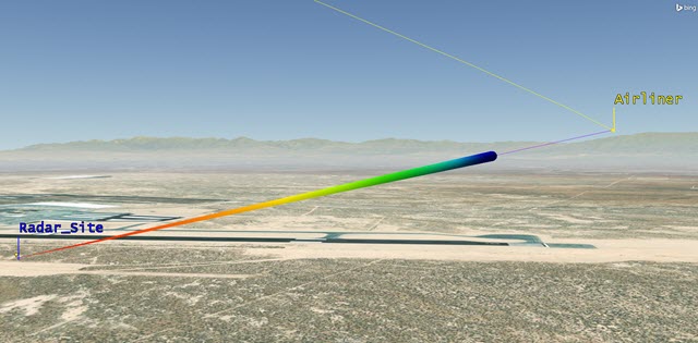
Target Airliner Tracking Airliner
Creating a custom report with Beam 1 (Target Airliner)
Now that Beam 1 targets the airliner, you determine exactly when Beam 1 can see the airliner during the scenario with an custom report. Later, you will repeat this process for the other three beams.
Computing Access
First, generate access intervals between MFRadar (![]() ) and Airliner (
) and Airliner (![]() ).
).
- Right-click MFRadar () in the Object Browser.
- Select Access... (
 ) in the shortcut menu.
 - Select Airliner () in the Associated Objects list when the Access tool opens.
- Click
 .
. - Click .
Creating the Beam 1 (TargetAirliner) report
Create a custom report using data providers that are important to your analysis.
- Select My Styles () in the Styles list.
- Click Create new report style (
 ) in the Styles toolbar.
 - Name the report Target Airliner.
- Press Enter on your keyboard to open the report's properties.
Choosing the required data providers
The content of a report or graph is generated from the selected data providers for the report or graph style.
- Select the Content page in the Report Style - Target Airliner dialog box.
- Expand (
 ) the Radar Multifunction (
 ) data provider in the Data Providers list.
 - Expand () the Target Airliner () group.
- Move () the following elements to the Report Contents field, in the order shown:
- Time (
 )
) - Waveform ID ()
- S/T Integrated SNR ()
- S/T Integrated PDet ()
- S/T Pulses Integrated ()
Adding azimuth and range to the report
Adding azimuth and range to your custom report enhances situational awareness.
- Scroll to the top of the Data Providers list.
- Expand () the AER Data () data provider.
- Expand () the Default () group.
- Move () the following elements to the Report Contents field, in the order shown:
- Azimuth ()
- Range ()
- Click to save the custom report style and dismiss the Report Properties Browser.
Generating the target airliner report
You want to see Integrated PDET values of 0.800000 or better. The remainder of the report provides you with enhanced situational awareness.
- Select Target Airliner (
 ) in My Styles ().
 - Click .
- Scroll through the report.
- Close the following windows when you are finished:
- Target Airliner report
- Report & Graph Manager
- Access Tool
Because you are switching the waveform strategy based on the airliner's distance from the radar site, you have good tracking except at longer ranges.
Configuring Beam 2 (Volume Search)
The Volume Search beam is sweeping the horizon, performing a volume search.
- Open MFRadar's () properties ().
- Select the Basic - Definition page.
- Select the Beams tab
- Click .
- Double-click Beam001 in the BeamID cell.
- Rename Beam001 to Volume Search.
- Select the Beam Spec tab.
- Enter 30 dB in the Gain field.
- Enter 5 deg in the BeamWidth field.
- Click to apply the changes and keep the Properties open.
You had to enter the gain before changing the beam width. You want a larger beam width, so your gain must be decreased. If you don't adjust the gain first, you will receive an error message due to an invalid sidelobe gain computation.
When creating two or more beams, whenever you click , the highlighted beam in the Beams list will jump to the top beam that you can see. Make sure to reselect the beam you are currently working with prior to making further changes. Otherwise, you will change the properties of the wrong beam.
Choosing a waveform strategy for Beam 2 (Volume Search)
- Return to the Components Browser ().
- Select Radar Waveforms in the Radar Components list.
- Select Rectangular () in the Radar Waveforms list.
- Click Duplicate component ().
- Type Volume Search Rectangular in the Name field when the Field Editor dialog box opens.
- Click to close the Field Editor dialog box.
- Double-click Volume Search Rectangular () in the Radar Waveforms list.
- Set the following options in the Waveform - Volume Search Rectangular dialog box:
- Click to close the Waveform - Volume Search Rectangular dialog box.
| Option | Value |
|---|---|
| Frequency | 3.5 GHz |
| Power | 50 dBW |
Applying the new volume search waveform
- Return to MFRadar's () properties ().
- Select the Basic - Definition page.
- Select the Beams tab.
- Select the Volume Search BeamID.
- Select the Waveforms tab.
- Click the Waveform component selector ().
- Select Volume Search Rectangular () in the Select Component dialog box.
- Click to close the Select Component dialog box.
- Click to apply the changes and keep the Properties Browser open.
Making Beam 2 a spinning beam
The spinning beam scans continuously for a full 360 degrees. The cone angle is 87 degrees with a spin rate of 60 degrees per second.
- Select the Volume Search BeamID.
- Select the Pointing tab below.
- Open the Pointing Type drop-down menu.
- Select Spinning.
- Set the following options in the Spinning panel:
- Click to apply the changes and keep the Properties Browser open.
| Option | Value |
|---|---|
| Cone Angle | 87 deg |
| Spin Rate | 60 deg/sec |
Visualizing Beam 2 (Volume Search)
- Bring the 3D Graphics window to the front.
- Zoom To Radar_Site ().
- Decrease Time Step () to 0.10 sec.
- Start () the animation.
- Reset () the scenario when you are finished.
Spinning and Targeted Beams
Creating a custom report with Beam 2 (Volume search)
- Right-click MFRadar () in the Object Browser.
- Select Access... ().
- Select PrivatePlane () in the Associated Objects list when the Access tool opens.
- Click .
- Click .
Create the volume search report
Analyze the difference between the airliner and the private plane.
- Select My Styles () in the Styles list.
- Click the Create new report style () in the Styles toolbar.
- Name the new report Volume Search.
- Press Enter on your keyboard.
Choosing the required data providers
You will choose which aspects of the scenario that you want the report to analyze.
- Select the Content page when the report's properties open.
- Expand () the Radar Multifunction () data provider in the Data Providers list.
- Expand () the Volume Search () group.
- Move () the following elements to the Report Contents field, in the order shown:
- Time ()
- S/T Integrated SNR ()
- S/T Integrated PDet ()
- S/T Pulses Integrated ()
- Click to save the custom report style and dismiss the Properties Browser.
Generating the volume search report
With the report for PrivatePlane set, you can compare it to the report for Airliner. You can generate the Volume Search for both aircraft in one report for easy comparison.
- Select Place-Radar_Site-Radar-MFRadar-To-Aircraft-Airliner (
 ) in the Object Type list.
 - Select Place-Radar_Site-Radar-MFRadar-To-Aircraft-PrivatePlane () in the Object Type list.
- Select Volume Search () in My Styles ().
- Click .
- Scroll through the report.
- Close the report when you are finished.
- Close the Access Tool.
- Keep the Report & Graph Manager open.
The volume search beam obtains reflections from both planes. The reflections from the small private plane are much stronger. There are a couple of instances in which the S/T Integrated PDet for the private plane is above 0.80000. The volume search picks up the private plane.
Configuring Beam 3 (Horizon Search)
Model one horizon search beam that is fixed in direction. An actual system could include many beams spread out in an arc both horizontally and vertically.
- Return MFRadar's () properties ().
- Select the Basic - Definition page.
- Select the Beams tab.
- Click .
- Double-click Beam001 in the BeamID cell.
- Rename Beam001 to Horizon Search.
- Select the Beam Spec tab.
- Change the Beam Width to 2 deg.
- Click to apply the changes and keep the Properties open.
Configuring the waveform strategy for Beam 3 (Horizon Search)
- Click Component Browser (), or bring it to the front if already open.
- Select Radar Waveforms in the components list.
- Select Rectangular () in the Radar Waveforms list.
- Click Duplicate component ().
- Type Horizon Search Rectangular in the Name field when the Field Editor dialog box opens.
- Click to close the Field Editor dialog box.
- Double-click Horizon Search Rectangular () in the Radar Waveforms list.
- Set Frequency to 3.5 GHz.
- Click to close the Waveform - Horizon Search Rectangular dialog box.
Applying the new horizon search waveform
- Return to MFRadar's () properties ().
- Select the Basic - Definition page.
- Select the Beams tab.
- Select the Horizon Search BeamID.
- Select the Waveforms tab.
- Click the Waveform component selector ().
- Select Horizon Search Rectangular () in the Select Component dialog box.
- Click to close the Select Component dialog box.
- Click to apply the changes and keep the Properties open.
Setting the pointing properties for Beam 3 (Horizon Search)
- Select the Horizon Search BeamID.
- Select the Pointing tab.
- Set the following:
- Click to apply the changes and keep the Properties open.
| Option | Value |
|---|---|
| Azimuth | 85 deg |
| Elevation | 3 deg |
Visualizing Beam 3 (Horizon Search)
- Bring the 3D Graphics window to the front.
- Zoom To Radar_Site ().

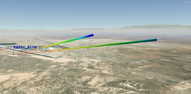
Targeted, Volume, and Horizon Search Beams
Determining when Beam 3 (Horizon Search) detects an aircraft
With Beam 3 configured, you will analyze the scenario by creating an Access report. You will use the report to determine when Beam 3 detects the private aircraft.
Creating a custom graph
Graph the horizon search beam to determine when the private plane flies through the beam.
- Return to the Report & Graph Manager.
- Set the Object Type to Access.
- Select Place-Radar_Site-Radar-MFRadar-To-Aircraft-PrivatePlane () in the Object Type: list.
- Right-click My Styles () in the Styles list.
- Select New in the first shortcut menu.
- Select Graph (
 ) in the second shortcut menu.
 - Type Horizon Search in the name field.
- Press Enter on your keyboard.
- Select the Content page in the report's properties.
- Expand () the Radar Multifunction () data provider in the Data Providers list.
- Expand () the Horizon Search () group.
Choosing the required data providers
In this instance, you'll graph the integrated signal to noise ratio and the integrated PDet values.
- Move () S/T Integrated SNR () to the Y Axis list.
- Move () S/T Integrated PDet () to the Y2 Axis list.
- Enter 1.000 sec in the Step Size field.
- Click to accept your changes and close the Graph Style Properties Browser.
Generate the horizon search graph
You will analyze the PrivatePlane with HorizonSearch.
- Select Horizon Search (
 ) in My Styles ().
 - Click .
- Place your cursor at the beginning of when the S/T Integrated PDet spikes and note the time, approximately 26 Apr 2023 18:13.
- Close the graph when you are finished.
When the private plane flies through the beam, S/T Integrated PDet and SNR (dB) spike. The S/T Integrated SNR (dB) rises as the range between the radar and the aircraft decreases. At the beginning of the graph, the private plane is approximately 66 kilometers away. It is about three (3) kilometers away at the time of closest approach. The S/T Integrated SNR increases in the middle of the graph because the range decreases and the private plane is in a side lobe.
With the “Goal SNR” default setting, you can integrate as many as 512 pulses. This compensates for the low SNR of a single pulse. When the range is shortest, the integration can increase the S/T Integrated SNR to a level that overcomes the loss of the beam gain. The integration of 512 pulses and close range work together to overcome the low side lobe gain. If power is increased in the waveform, there could be a S/T Integrated PDet spike.

Horizon Search Graph Example
Setting the first time interval for Beam 3 (Horizon Search)
The Time Interval start and stop times that you enter in the list define the time intervals when the beam is active. When the Time Intervals option is selected, the table contains a summary of the start and stop times for each period when the beam is active. The interval is "closed/opened," which means that the start time is included in the interval but the stop time is not. The intervals list provides an easy reference that outlines basic information. You can add, load, import, and remove time intervals.
Horizon Search begins searching at the scenario start time. Stop Horizon Search at the time that it switches to active targeting.
- Return to MFRadar's () properties ().
- Selct the Basic - Definition page.
- Select the Beams tab.
- Select the Horizon Search BeamID.
- Select the Active Times tab.
- Open the drop-down menu.
- Select Time Intervals.
- Click .
- Set the Stop Time to 26 Apr 2023 18:13:30.000 UTCG. Although Horizon Search sees the private plane at 18:13 UTCG, tracking starts at 18:13:30. You are setting this beam to switch to the targeted beam at the right time.
- Click to apply the changes and keep the Properties Browser open.
Configure Beam 4 (Horizon Targeted)
After Horizon Search detects the private plane, it switches to active tracking. To model this, insert a new beam that simulates Horizon Search, but targets the private plane instead.
- Select the Beams tab.
- Click .
- Double-click Beam001 in the BeamID list.
- Type Horizon Targeted.
- Select the Beam Spec tab.
- Set the following:
- Click to apply the changes and keep the Properties open.
| Option | Value |
|---|---|
| Beam Width | 1.4 deg |
| Gain | 30 dB |
Choosing a waveform strategy for Beam 4 (Horizon Targeted)
You can apply the same four-ranged waveform strategies used with Beam 1 because Beam 4 is also a tracking beam.
Applying the short-range waveform
- Select Horizon Targeted in the BeamID list.
- Select the Waveforms tab.
- Open the drop-down menu.
- Select Range.
- Select Override Default for Short Range, Medium Range, Long Range, and Ultra Long Range.
- Click the Short Range: Waveform component selector ().
- Select Airliner Short Range Rectangular () in the Select Component dialog box.
- Click to close the Select Component dialog box.
Apply the medium-range waveform
- Click the Medium Range: Waveform component selector ().
- Select Airliner Medium Range Rectangular () in the Select Component dialog box.
- Click to close the Select Component dialog box.
Apply the long-range waveform
- Click the Long Range: Waveform component selector ().
- Select Airliner Long Range Rectangular () in the Select Component dialog box.
- Click to close the Select Component dialog box.
Apply the ultra-long-range waveform
- Click the Ultra Long Range: Waveform component selector ().
- Select Airliner Ultra Long Range Rectangular () in the Select Component dialog box.
- Click to close the Select Component dialog box.
- Click to apply the changes and keep the Properties Browser open.
Setting the pointing options for Beam 4 (Horizon Targeted)
- Select Horizon Targeted in the BeamID list.
- Select the Pointing tab.
- Open the Pointing Type drop-down menu.
- Select Targeted.
- Move () PrivatePlane () from the Available Targets list to the Assigned Target list.
- Click to apply the changes and keep the Properties Browser open.
Setting a start time for Beam 4 (Horizon Targeted)
Start tracking the private plane at 18:13:30 UTCG.
- Select Horizon Targeted in the BeamID list.
- Select the Active Times tab.
- Open the Active Times drop-down menu.
- Select Time Intervals.
- Click .
- Set the Start Time to 26 Apr 2023 18:13:30.000 UTCG.
- Click to apply the changes and keep the Properties Browser open.
Creating a custom graph using Beam 4 (Horizon Targeted)
- Return to the Report & Graph Manager.
- Ensure the Object Type is set to Access.
- Select Place-Radar_Site-Radar-MFRadar-To-Aircraft-PrivatePlane ().
- Select My Styles () in the Styles list.
- Click Create a new graph style () in the Styles toolbar.
- Type Horizon Targeted in the name field.
- Press Enter on your keyboard.
- Select the Content page when the reports properties open.
- Expand () the Radar Multifunction () data provider.
- Expand () the Horizon Targeted () group.
Define the graph
- Move () S/T PDet1 () to the Y Axis list.
- Move () S/T Integrated PDet () to the Y Axis list. It is easier to compare two values when they are on the same axis
- Change Step Size to 1.000 sec.
- Click to accept your changes and dismiss the Graph Style Properties Browser.
Generate the horizon targeted graph
With Horizon Targeted, you can analyze PrivatePlane (![]() ). Remember, Horizon Targeted is simulating when Horizon Search switches from a fixed-search mode to a tracking mode.
). Remember, Horizon Targeted is simulating when Horizon Search switches from a fixed-search mode to a tracking mode.
- Select Horizon Targeted () in My Styles ().
- Click .
- Close the graph when you are finished.
- Close the Report & Graph Manager.
- Close the Component Browser.
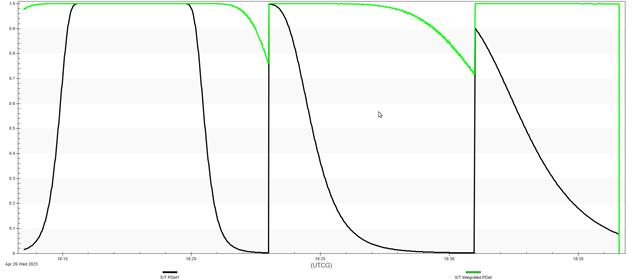
S/T PDet1 uses one pulse and S/T Integrated PDet uses up to 512 pulses; you can change the default number of pulses to match your system. You can see on the graph that both S/T PDet1 and S/T Integrated PDet show reflections from the private plane. You can see the difference between the two: the S/T PDet1 values drop twice, while the S/T Integrated PDet values are good except two instances where they drop below 0.8.
Setting the second time interval for Beam 3 (Horizon Search)
Now you have all the information you need to jump back to Beam 3 and set a second time interval. Beam 3 (Horizon Search) resumes a fixed search at 18:30:00 UTCG and stays on for the remainder of the scenario.
- Return to MFRadar's () properties ().
- Select the Basic - Definition page.
- Select the Beams tab.
- Select the Horizon Search in the BeamID list.
- Select the Active Times tab.
- Click .
- Set the Start Time to 26 Apr 2023 18:30:00.000 UTCG in the second interval.
- Click to apply the changes and keep the Properties Browser open.
Setting the stop time for Beam 4 (Horizon Targeted)
After creating the second time interval for Beam 3, Horizon Targeted can stop tracking the private plane at 18:30:00 UTCG and stay off for the remainder of the scenario.
- Select Horizon Targeted in the BeamID list.
- Select the Active Times tab.
- Set the Stop Time to 26 Apr 2023 18:30:00.000 UTCG.
- Click to apply the changes and dismiss the Properties Browser.
Animating the scenario
You have built the multifunction radar beams and analyzed them with report. Now you can animate the scenario and see the beams interacting with the aircraft.
- Target Airliner follows the large airliner.
- Volume Search does a continuous 360 degree sweep of the horizon.
- Horizon Search points along its programmed direction until the small private plane enters its beam. It then switches to active tracking.
- When Horizon Targeted's integrated probability of detection falls below 0.50, it turns off and Horizon Search turns back on.
- Reset () the scenario.
- Enter 26 Apr 2023 18:13:00.000 in the Current Scenario Time field of the Animation toobar.
- Press Enter. This moves your scenario to 30 seconds prior to the Horizon Targeted beam seeing the private plane.
- Start () the animation. You can increase the time step (
 ) if desired.
 - Reset () the scenario when you are finished.
Tracking the Private Plane and the Airliner
Summary
You created a multifunction radar that contained four beams. The first beam tracked a large airliner. You used the Component Browser to create four unique waveforms that automatically switched based on the distance from the airliner to the radar site. The second beam was a spinning volume search that you used to compare tracking between a small private plane and the airliner. Your third beam was a fixed horizon search beam. When the small private plane flew through the third beam's field of view, the multifunction radar system switched from beam three to beam four. Beam four was a horizon targeted beam using the airliner's waveforms, and tracked the private plane. You applied time intervals to the fixed horizon search and horizon targeted beams to simulate switching from a horizon search beam to the horizon targeted beam and back. Throughout your analysis, you created custom reports and graphs to analyze your radar system.
On your own
There are many settings that you did not use in this scenario. For example, you could use additional gains and losses, orthogonal polarization, clutter, and detection processing. You could enable analytical terrain to set up an Azimuth Elevation Mask for the radar site. But with the knowledge you have learned from this exercise and with the STK Help at your side, you should be able to explore all these facets of the STK multifunction radar capability. Have fun!