The results of the tutorial may vary depending on the user settings and data enabled (online operations, terrain server, dynamic Earth data, etc.). It is acceptable to have different results.
Problem Statement
You are working for the FAA and your boss is concerned about the possibility of an unauthorized aircraft flying from Havana to Key Largo. Your boss wants you to examine an early warning detection system in Miami that works in concert with an existing tracking radar attached to a satellite traveling in a low-earth orbit (LEO). You want to send this scenario to your colleagues and supervisors at both Miami and Key Largo. Keep in mind, they do not have STK.
Break It Down
You have some information that may be helpful. Here’s what you know:
- You need an early warning detection system that will “catch” the unauthorized aircraft flying to Key Largo from Havana, Cuba at an altitude of 5,000 feet.
- You can use a satellite to monitor any unauthorized aircraft flying from Havana airport.
- You know that the satellite is equipped with both a fixed field-of-view radar and another radar that can gimbal to track objects, but you need to determine which system will track intruders more efficiently.
- You need to design a radar net over Miami.
Solution
Model a scenario that allows you to consider and compare all of your system options. Simulate an aircraft traveling from Havana to Key Largo and determine which portion of the aircraft's route can be tracked by the various radars.
Model the World!
The first thing you need to do is create a scenario.
- Click the Create a Scenario button.
- Enter the following in the New Scenario Wizard:
You need to define the times during which the conditions that you set for your world, and the objects in your world, will be relevant. You will only be sampling a small portion of the day--just enough time to fly from Havana to Key Largo. Three hours should more than cover it.
Model the World!
When you click the Create a New Scenario button, the New Scenario Wizard appears. You can input basic information about the scenario here. Let’s set the basic parameters for scenario creation now.
- Enter the following in the New Scenario Wizard.
- When you finish, click OK to dismiss the New Scenario Wizard.
- When the scenario loads, click Save (
 ).
).
| Option | Value |
|---|---|
| Name | Rogue_Aircraft |
| Description | Can I detect a rogue aircraft flying from Havana to Key Largo? |
| Location | C:\Users\<username>\Documents\STK 12\ |
| Start & Stop (Analysis Period) | Change the default analysis period so that it spans only three hours. |
A folder with the same name as your scenario is created for you in the location specified above.
So, now you have a world. Before you can build the early warning system simulation, you’ll populate the world with all the “players” - you’ll add Miami, Key Largo, and Havana, and an aircraft to fly through your tracking systems.
Model Destinations
See if you can find a database entry for Miami, Key Largo, and Havana, and use them to model STK facility objects representing the city where your boss wants you to place the early warning system (Miami) and the aircraft's home port (Havana), and the aircraft target (Key Largo).
- Locate the Search bar within the STK workspace.
- In the Search field, type Miami, FL.
- Click Enter to search the City Database for Miami, Florida.
- When the search results appear, double-click the Miami, Florida entry.
- Follow the same steps to insert Havana, Cuba and Key Largo, FL.
A new place object will be inserted into the STK scenario.
This method only works with a valid internet connection. If you do not have an internet connection, you can use the City Database to model these cities.
Model the Intruder
Your next “player” is an aircraft that you’ll use to model a possible smuggler. In STK, an aircraft is an airborne Great Arc vehicle.
- Select the following in the Insert STK Objects tool (
 ):
): - Click the Insert... button.
| Option | Value |
|---|---|
| Select an Object to be Inserted: |
|
| Select a Method |
|
When you click the Insert... button, the Orbit Wizard will appear.
Get a Better Look
- Bring the 2D Graphics window to the front.
- Zoom In (
 ) around Havana (
 ) and Key Largo ().
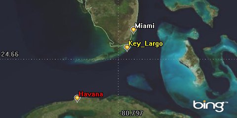
2D View: Zoom to Key Largo and Havana
Define a Route
Of course, an aircraft doesn’t travel on the central body at zero (0) altitude the way that a ship or ground vehicle would, but its route is also defined with respect to the central body at a specified altitude.
- Ensure that the Basic - Route page for the new aircraft (
 ) is selected.
 - Ensure that the Propagator option is set to GreatArc.
- With the Route page open, click Havana () on the map in the 2D Graphics window.
- Go back to the aircraft’s () properties (
 ).
). - Double-click the altitude field for the first waypoint to make it editable.
- Change the Altitude value to 5000 ft.
- Press the Enter key on your keyboard. The altitude value will automatically be converted to kilometers (the default distance unit set at the scenario level).
- Click Key_Largo () on the map in the 2D Graphics window. A second way point (at 1.524 km altitude) will be entered in the table on the Route page.
- Click OK.
- Rename the new aircraft () Rogue_Aircraft.
Don’t forget to include the ft unit abbreviation.

2D View: Rogue aircraft's route
Model a LEO Satellite
Another "player" to add to your scenario is the satellite that you are going to use to try to track the rogue aircraft as it runs for Key_Largo.
- Select the following in the Insert STK Objects tool ():
- Click the Insert... button.
- Click OK.
| Option | Value |
|---|---|
| Select an Object to be Inserted: |
|
| Select a Method |
|
| Option | Value |
|---|---|
| Type | Repeating Ground Trace |
| Satellite Name | Airport_Watch |
| Longitude of the First Ascending Node | -90 deg |
Zoom To It!
Use the Zoom To option to center the view in the 3D Graphics window on Airport_Watch, so that you will have a birds eye view of our camera angles as you add them.
- Zoom To the Airport_Watch (
 ) satellite in the 3D Graphics window.
 - Mouse around in the window to get a good view of Airport_Watch’s () perspective of the Earth.
No matter which Type of orbit you select, the Orbit Wizard lets you change the satellite analysis period as well as configure and preview satellite graphics before the object is introduced into the scenario.
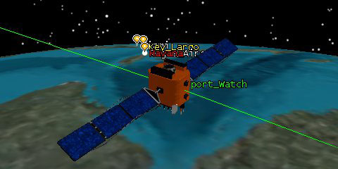
3D View: Airport_Watch
Model Instruments
It’s time to design your early warning detection system. You’ll use sensors to model the various components that make up the system.
An STK sensor object can be used to represent the field-of-view, the overall volume of space, and such instruments as optical or radar sensors, receiving or transmitting antennas, and lasers. Sensor objects model generic payloads and as such must be a child, or subordinate, object of a facility, target, or vehicle object.
Fixed Sensors on Moving Objects
The default STK sensor model will create a nice representation of a sensor with a fixed field-of-view. Attach a sensor to Airport_Watch, and see if you can detect the rogue aircraft as it makes its move on Key_Largo.
- Select the following in the Insert STK Objects tool ():
- Click the Insert... button.
- Select Airport_Watch () in the Select Object dialog.
- Click OK.
- When the new sensor (
 ) appears in the Object Browser, rename it Fixed.
| Option | Value |
|---|---|
| Select an Object to be Inserted: |
|
| Select a Method |
|
When you select an Attached Object for insertion, STK requires that you select the parent object for the object being created. In this example, you want to attach the first sensor that you’ll create to the Airport_Watch satellite.
The default sensor that STK creates when you introduce a sensor object is a simple conic sensor with a 45 degree cone angle. The default sensor view is fixed at zero (0) degrees azimuth and 90 degrees elevation which is nadir pointing. When a sensor object is attached to a moving object it points with respect to the parent object’s reference frame. A fixed sensor is always pointing in a fixed direction with respect to its parent object.
Get a Better Look
- Bring the 3D Graphics window to the front.
- Mouse around to get a clear view of the fixed sensor's field-of-view.
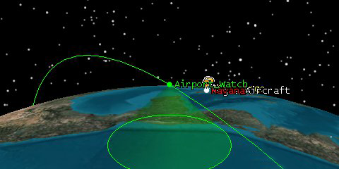
3D View: Fixed sensor field-of-view
When Can the Fixed Sensor "See" It?
Let's find out if the new sensor (Fixed) can "see" the rogue aircraft.
- Open the Access tool (
 ).
). - Set the following:
- Click the Compute (
 ) button.
| Option | Value |
|---|---|
| Access For: | Fixed |
| Associated Objects | Rogue Aircraft |
Get Moving!
- Position the 2D and 3D Graphics windows so that they are both clearly visible.
- Reset (
 ) the animation.
 - Play (
 ) the animation, and watch as Airport_Watch () travels along its path.
 - When you finish, Reset () the animation.
- Were there visible accesses between the fixed sensor and the rogue aircraft?
- Bring the Access tool () to the front.
- Click the Access... button in the Reports area.
- After reviewing the data, close the report window.
- Close the Access tool ().
According to your data, Fixed can’t see the rogue aircraft coming at all. Well, that didn't work so well. Let’s try adding a second sensor that is targeted towards the rogue aircraft.
Moving Sensors on Moving Objects
When you attached the first sensor, you used the default fixed pointing type. In reality, most satellites can gimbal their sensors to track other objects (stationary and moving). STK provides a variety of sensor definition and pointing types that allow you to model this type of movement.
- Select the following in the Insert STK Objects tool ():
- Click the Insert... button.
- Select Airport_Watch () in the Select Object dialog.
- Click OK.
- Rename the sensor Targeted.
| Option | Value |
|---|---|
| Select an Object to be Inserted: |
|
| Select a Method |
|
Targeted Sensor Definition
To create a sensor that will move to target the Rogue Aircraft, you'll again, use the Simple Conic type, but this time, you’ll make the cone angle much smaller. You don’t need a large field-of-view because the sensor is targeted directly at the object-of-interest.
- Open Targeted’s () properties ().
- Ensure that the Basic - Definition page is selected.
- Set the following Definition properties:
- Click Apply.
| Option | Value |
|---|---|
| Sensor Type | Simple Conic |
| Cone Angle | 5 Deg |
Sensor Pointing
Targeted sensors track other objects. A targeted sensor is positioned with respect to the parent object, but instead of pointing in a fixed direction, it will move about so that its boresight is pointing in the direction of the object that it targets when the aircraft is in the sensor’s field-of-view. Let’s use a targeted sensor so it can monitor the rogue aircraft at all times.
- Select the Basic - Pointing page.
- Set the following Pointing properties.
- Select the Rogue_Aircraft () in the Available Targets list.
- Click the button to move Rogue_Aircraft () to the Assigned Targets list.
- Click on the Target Times... button.
- When does access to the rouge aircraft begin?
- Click OK to close the Target Times window.
- Click OK.
| Option | Value |
|---|---|
| Pointing Type | Targeted |
| Boresight Type | Tracking |
This is an easy way to see if access exists between the targeted sensor and its targeted object/objects without actually computing access.
If you want to change the color of the Targeted sensor, you can do so by going to the 2D Graphics Attributes page.
Get a Better Look
- Position the 2D and 3D Graphics windows so that you can see them both clearly.
- Play () the animation.
- Can you see the targeted sensor’s field-of-view?
- Why does the targeted sensor’s field-of-view disappears from time to time?
- Were there visible accesses between the targeted sensor and the rogue aircraft at the time the aircraft is taking off?
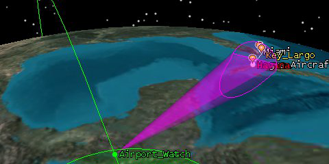
3D View: Targeted sensor field-of-view
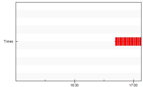
When Can Targeted "See" It?
- Open the Access tool ().
- Set the following:
- Click the Access... button in the Graphs area.
- Use access data to answer the following questions:
- Can the targeted sensor “see” the potential intruder?
- Is the rogue aircraft’s entire flight detectable?
- If not, during what portion of the rogue aircraft’s flight is it detectable?
- For how long?
- Close the Access Graph.
- Close the Access tool ().
| Option | Value |
|---|---|
| Access For: | Targeted |
| Associated Objects | Rogue Aircraft |
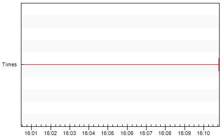
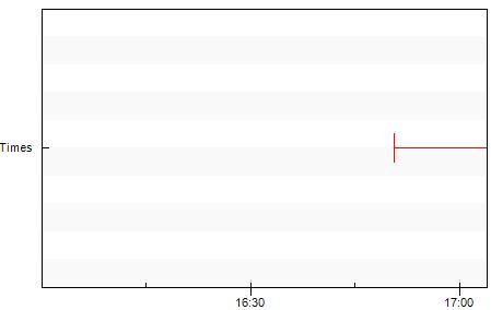
Graph: Access From Targeted to Rogue Aircraft
Model the Detector Aircraft
The United States has placed a surveillance aircraft around the Florida Keys. The crew’s job is to monitor illegal smugglers that fly too low to be detected by normal radar. Let’s model that route now:
- Select the following in the Insert STK Objects tool ():
- Click the Insert... button.
- Rename the aircraft Detector.
| Option | Value |
|---|---|
| Select an Object to be Inserted: |
|
| Select a Method |
|
Define a Route
- Ensure that the Basic - Route page for the new aircraft () is selected.
- Ensure that the Propagator option is set to GreatArc.
- With the Route page open, click Key_Largo () on the map in the 2D Graphics window.
- Go back to the aircraft’s () properties ().
- Double-click the altitude field for the first waypoint to make it editable.
- Change the Altitude value to 15000 ft.
- Press the Enter key on your keyboard. The altitude value will automatically be converted to kilometers (the default distance unit set at the scenario level).
- Feel free to click a box around Key Largo that will represent the flight route of the detecting aircraft.flight route of the detecting aircraft.
- Click OK when you feel comfortable with Detector’s () route.
Don’t forget to include the ft unit abbreviation.
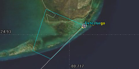
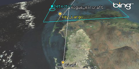
2D View: Detector's flight route
Change Your Perspective
- Zoom In Detector () in the 3D Graphics window.
- Mouse around until you get a clear view of Detector ().
Fixed Sensor on a Moving Object
You have a detecting aircraft with an on-board radar flying at 15,000 feet surveilling the Florida Keys. Let’s create the on-board sensor.
- Select the following in the Insert STK Objects tool ():
- Use the Insert Default method to attach a sensor () to Detector ().
- Rename the new sensor () Rogue_Detect.
Sensor Definition
Let's model the sensor of the aircraft. The sensor has a 40 degree cone angle.
- Open Rogue_Detect’s () properties ().
- Ensure that the Basic - Definition page is selected.
- Set the following Definition properties:
- Click OK.
| Option | Value |
|---|---|
| Sensor Type | Simple Conic |
| Cone Angle | 40 deg |
Visually Verify Access
Let's animate the scenario and see if your detector aircraft can spot the rogue aircraft.
- Bring the 3D Graphics window to the front.
- Play () the animation.
- Watch as the Rogue_Aircraft travels from Havana to Key_Largo.
- Can Rogue_Detect “see” rogue aircraft?
- If so, for how long?
- If not, can you modify the detector’s route to better see the rogue aircraft?
- When you finish, Reset () the animation.
Fixed Sensors on Stationary Objects
Now that you know some of your assets can monitor the rogue aircraft shortly after takeoff, and can then pass this information back down to the ground. To complete your early warning detection system, you need to model the radar “net” in Miami. First, you’ll simulate a stationary radar dome attached to Miami.
In the previous examples, you attached sensors to moving objects to model a tracking system. Sensors can also be used to model instruments attached to stationary objects, such as facilities and targets. Fixed sensors attached to stationary objects also point with respect to the parent object’s reference frame. Since stationary objects never change position or direction, a fixed sensor will always point in a fixed direction with respect to the parent object.
- Select the following in the Insert STK Objects tool ():
- Use the Insert Default method to attach a sensor () to Miami ().
- Rename the new sensor () Radar_Dome.
Define a Radar Dome
| Option | Value |
|---|---|
| Sensor Type | Simple Conic |
| Cone Angle | 90 deg |
Constrain a Radar Dome
The sensor created here is similar to the fixed sensor attached to Airport_Watch, but it has a larger field-of-view, and instead of pointing straight down this one points straight up from the Miami facility. It has an up looking field-of-view that covers everything above Miami. That’s not very realistic. Let’s limit its range so that the field-of-view spans a constrained area around Miami.
- Select the Constraints - Basic page.
- In the Range area, enable the Max. option.
- Enter 200 km in the adjacent textbox.
- Click Apply.
Projection Display
2D Graphics Projection properties for sensors control the display of sensor projection graphics in the 2D Graphics window. Sensors attached to facilities and targets differ in their display behavior from those attached to vehicles. The intersections of vehicle-based sensors with the Earth are displayed during animation.
The Extension Distances option indicates whether the sensor’s field-of-view crossings at specified distances are computed and displayed in the 2D Graphics window. When the sensor display is set to project to the range constraint, STK projects the sensor field-of-view to the maximum range specified on the Basic Constraints properties page for the facility or target.
- Select the 2D Graphics - Projection page.
- Set the following Extension Distances options.
- Click OK.
| Option | Value |
|---|---|
| Use | On |
| Project To | Use Range Constraint |
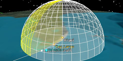
Get a Better Look
- Ensure that the view is set on Miami ().
- Mouse around to get a better look at the radar dome.
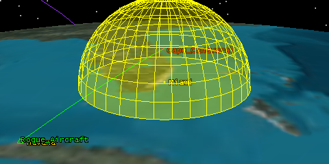
3D View: Radar Dome sensor attached to Miami
When Can the Radar Dome "See"?
Can you see the radar dome that you modeled?
- Play () the animation.
- Watch as the Rogue_Aircraft travels from Havana to Key_Largo.
- Did you see the Rogue_Aircraft enter and then exit the radar dome?
- When you finish, Reset () the animation.
When Can the Radar Dome "See" It?
You know that the Rogue_Aircraft travels through the radar dome, which constitutes an access, but when do accesses occur? For how long? Check to see.
- Open the Access tool ().
- Set the following:
- Click the Compute () button.
- Position the windows such that the 2D and 3D Graphics windows are clearly visible.
- Position the 2D and 3D Graphics windows so that you can see them both clearly.
- Play () the animation.
- Are there accesses between Radar_Dome and the Rogue_Aircraft?
- When you finish, Reset () the animation.
| Option | Value |
|---|---|
| Access For | Radar_Dome |
| Associated Objects | Rogue Aircraft |
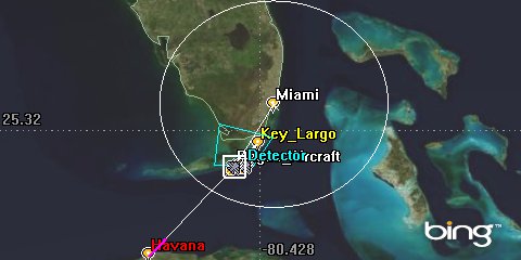
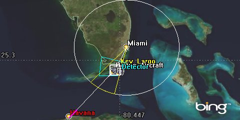
2D View: Access from Radar Dome to Rogue Aircraft
3D View: Rogue Aircraft in Radar Dome
Access Data
Generate some hard data to help you determine when and for how long the rogue aircraft is in the dome.
- Open the Access tool ().
- Set the following:
- Click the Access... button in the Graphs area.
- Use access data to answer the following questions:
- Can Radar_Dome detect the Rogue_Aircraft?
- Is the Rogue_Aircraft’s entire flight detectable?
- If not, during what portion of the Rogue_Aircraft’s flight is it detectable?
- For how long?
- When you finish, close the Access graph.
- Close the Access () tool.
| Option | Value |
|---|---|
| Access For: | Radar Dome |
| Associated Objects | Rogue Aircraft |
Graph: Access from Radar Dome to Rogue Aircraft
Moving Sensors on Stationary Objects
Often, the dome created by a sensor is used to model a field-of-view, or the overall volume of space in which radar looks. The radar itself often sweeps or scans through that field-of-view in a repeating cycle. The area of space represented by such a scanning or spinning radar at any given instant is its field-of-view. Add another level of fidelity to your scenario and build a sweeping radar beam using a moving sensor.
Just as you were able to track the Rogue_Aircraft using a sensor that moved independent of its parent object, you can also model instruments attached to stationary objects that move independent of the object to which they are attached. Spinning sensors are often used to model radars, push broom sensors, and other instruments that spin, scan, or sweep over time.
- Use the Insert Default method to attach a second sensor () to Miami ().
- Rename the new sensor () Radar_Sweep.
- Open Radar_Sweep’s () properties ().
- Ensure that the Basic - Definition page is selected.
- Set the following Definition properties:
- Click Apply.
| Option | Value |
|---|---|
| Sensor Type | Complex Conic |
| Inner Half Angle | 0 Deg |
| Outer Half Angle | 90 Deg |
| Minimum Clock Angle | 0 Deg |
| Maximum Clock Angle | 90 Deg |
Sensor Pointing
The above configuration should create a wedge type field-of-view. Right now, that “wedge” is just pointing straight ahead. You want the wedge to spin and scan the radar dome continuously. Spinning sensor model radars, push broom sensors and other instruments that spin, scan or sweep over time. Let’s take a look.
- Select the Basic - Pointing page.
- Set the following Pointing properties:
- Click Apply.
| Option | Value |
|---|---|
| Pointing Type | Spinning |
| Spin Rate (Revs/Min) | 5 |
| Spin Axis Cone Angle | 0 |
If you want to change the color of the Radar Sweep, you can do so by going to the 2D Graphics Attributes page or click the colored square beside the object in the Object Browser.
Constrain a Sweeping Radar
Right now the sweeping radar extends beyond the limits of the radar dome because you haven't constrained it. Let’s limit the range of the radar so that it scans only the inside of the dome.
- Select the Constraints - Basic page.
- Set the following constraint:
- Click Apply.
| Option | Value |
|---|---|
| Max Range | On |
| Max Range | 200 km |
Projection Display
You would like to project the sensor on the 2D and 3D Graphics window to the range constraint you set earlier. You set the range constraint in the Basic - Constraints page for the facility. If you don’t enable the range constraint here, the constant range from the parent object will be used.
- Select the 2D Graphics - Projection page.
- Set the following Extension Distances options:
- Click OK.
- You don’t need to create any more objects, so you can close the Insert STK Objects tool () now if you like.
| Option | Value |
|---|---|
| Use | On |
| Project To | Use Range Constraint |
Get a Better Look
- Use the Decrease Time Step button (
 ) to decrease the time step to one second.
 - Play () the animation. Notice how Radar_Sweep () continuously scans around Miami.
- Reset () the animation.
If your animation time step is an even multiple of your spin rate, you will not see motion of the sensor when you animate.
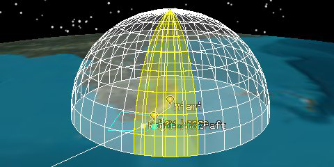
3D View: Radar Sweep sensor attached to Miami
What Can the Sweeping Radar "See"?
- Compute Access () FROM Radar_Sweep () TO the Rogue_Aircraft ().
- Position the 2D and 3D windows so that they are both clearly visible.
- Are there visible accesses between Radar Seep and the Rogue Aircraft?
3D View: Access from Radar Sweep to Rogue Aircraft
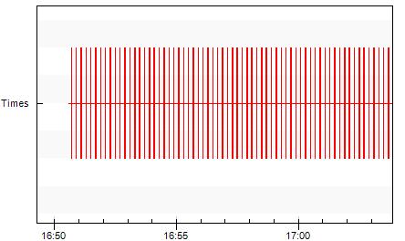
When Can the Sweeping Radar “See” It?
You know that Radar_Sweep brushes over the Rogue_Aircraft repeatedly as the intruder travels from Havana to Key_Largo, which constitutes access, but when do accesses occur? How many? For how long? Check and see.
- Return to the Access () tool.
- Generate an Access graph.
- Use the Zoom In () tool to zoom in on a section of the graph.
- Close the Access graph.
- Return to the Access tool ().
- Generate an Access report.
- Using access data, answer the following questions:
- Is the Rogue_Aircraft's entire flight detectable?
- If not, during what portion of the Rogue_Aircraft's flight is it detectable?
- Leave the Access report open. You will need it in a minute.
Graph: Access from Radar Dome to Rogue Aircraft
At first glance, it appears that you have one continuous access, but this is not the case. Because the accesses are so short and close together, you can’t identify the individual accesses from this graph. The Zoom In tool can be used on a graph much like it can be on the 2D Graphics window.
The Zoom In tool is embedded in the functionality of the mouse. If you left-click on your mouse and hover over an item on the graph, you can draw a box around the item and zoom closer.
Graph: Zoom in section of the graph
Due to the number of accesses, an access report might be more helpful in providing statistical data on these accesses.
Log Your First Alert
You want your colleagues to know the instant that the Rogue_Aircraft is caught by Radar_Sweep inside the dome. Let’s store a view that depicts just that.
- Reposition your view so that Miami () is the focal point in the 3D Graphics window, if it is not already.
- Right-click the first access time from the Access report.
- Select Start Time --> Set Animation Time from the context menu.
- Mouse around until you are happy with the view.
- Click Stored Views (
 ) on the 3D Graphics toolbar.
 - Click New.
- Rename View0 FirstAccess.
- Click OK.
- Close the Access report.
The view should show the rouge aircraft breaching the perimeter of the radar dome.
3D View: First access
The view of Miami and the associated time are now saved for immediate recall. To recall a view at any time, select it from the drop-down menu beside the Stored Views button (![]() ) on the 3D Graphics toolbar.
) on the 3D Graphics toolbar.
Who "Sees" It When?
Return to STK and compare the sensors that had access to the rogue aircraft.
- Bring the Access tool () to the front.
- Set the following:
- Click the Access button in the Graph area.
- Use the Access Graph (
 ) to answer the following questions:
 - Why doesn’t data for the all of the sensor’s display on the graph?
- Can you see the difference between the access times for the various sensors?
- Close the Access tool ().
- Close the Access graph.
| Option | Value |
|---|---|
| Access For | Rogue Aircraft |
| Associated Objects |
Select all of the sensors Fixed Targeted Rogue Detect Radar Sweep Radar Dome |
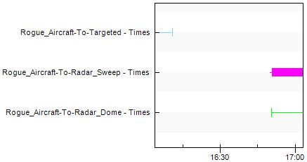
Graph: Access from the rogue aircraft to sensors
Share Scenarios With Non-STK Users
Now you want to send this scenario to your colleagues and supervisors at both Miami and Key_Largo; however, they do not have STK. You could send them the raw text data, but you would really like for them to be able to “see” how the different tracking instruments perform. How can they interact with your STK scenario without installing STK?
Simple--your colleagues can download a free copy of AGI Viewer! AGI Viewer enables users of any technical level to view and interact with STK analyses via a VDF file--4D scenes of time-varying STK analyses. These files are created with STK. STK’s publishing capability allows users to save scenarios as VDF files, and share them with anyone, regardless if they have STK or not.
Pack It Up
You’ve stored the view that you want them to see. Now you need to create a VDF file that can be opened using the free AGI Viewer tool.
- Save () the scenario (
 ).
). - Select Rogue_Aircraft () in the Object Browser.
- Extend the File menu.
- Select VDF Setup...
- Enable the Minimal VDF option.
- Click the Create VDF... button.
- Click Save.
- Minimize the STK application.
When the dialog comes up, the Minimal VDF option is off by default. If Minimal VDF is on, STK creates the smallest possible VDF file that can be opened in STK and AGI Viewer. The Minimal VDF option will include only the default data sets in your VDF file. (The default data sets are selected when the Minimal VDF option is enabled.). Clear the Minimal VDF option to include analysis files, globe data files, graphics files, and/or scenario files with the VDF file.
STK should default to the same directory where the Rogue_Aircraft scenario is stored. If it does not, locate the Rogue_Aircraft directory that you created earlier.
If you selected the Minimal VDF option, you should open and view the VDF you created to ensure all critical information is included in the file.
View the Rogue Aircraft
It’s always a good idea to review the VDF before you send it.
- Locate the directory where your scenario is saved (C:\Users\<username>\Documents\STK 12\).
- Double-click the Rogue_Aircraft.vdf (
 ) file. The AGI Viewer application will launch automatically.
 - Experiment with playing () and pausing (
 ) the animation, zooming, mousing around in the 3D Graphics window, and switching to a Stored Views ().
The controls at the top of the window work exactly the same as they did in STK.
While there is no View To/From button, you can still focus the 3D window on a particular object by right-clicking and selecting View Object.
When You Finish
- Close AGI Viewer ().
- Return to STK (
 ).
). - Reset () the animation.
- Restore the view in the 3D Graphics window ().
- Save () your work.
- Close the scenario ().
- Leave STK () open.