STK Pro, STK Premium (Air), STK Premium (Space), or STK Enterprise
You can obtain the necessary licenses for this tutorial by contacting AGI Support at support@agi.com or 1-800-924-7244.
This lesson requires version 12.9 of the STK or newer to complete in its entirety. If you have an earlier version of the STK software, you can complete a
The results of the tutorial may vary depending on the user settings and data enabled (online operations, terrain server, dynamic Earth data, etc.). It is acceptable to have different results.
Capabilities covered
This lesson covers the following capabilities of the Ansys Systems Tool Kit® (STK®) digital mission engineering software:
- STK Pro
- Coverage
Problem
You require a fast, easy way to set up and analyze a group of satellites as a single object. Your satellite collection object must support metadata for additional descriptive information and support categorization into subsets.
Solution
Use the STK software to model large constellations of satellites using a Satellite Collection object and associated external files.
What you will learn
Upon completion of this tutorial, you will understand:
- How to use a Satellite Collection object
- How to create custom orbit definition files
- How to create reference objects
- How to use Satellite Collection objects analytically
- How to use the Deck Access Tool
- How to use routing files
Video guidance
Watch the following video. Then follow the steps below, which incorporate the systems and missions you work on (sample inputs provided).
Creating a new scenario
First, you must create a new scenario and then build from there.
- Launch the STK application (
 ).
). - Click
 Create a Scenario in the Welcome to STK dialog box.
 - Enter the following in the STK: New Scenario Wizard:
- Click when you finish.
- Click Save (
 ) when the scenario loads. The STK software creates a folder with the same name as your scenario for you.
 - Verify the scenario name and location in the Save As dialog box.
- Click .
| Option | Value |
|---|---|
| Name | SatelliteCollection |
| Location | Default |
| Start | Default |
| Stop | Default |
Save (![]() ) often during this lesson!
) often during this lesson!
Inserting a Satellite Collection object
A Satellite Collection object models a group of satellites as a single object in the Object Browser. The Satellite Collection object primarily serves as a data store that the STK software uses, like a recipe, to generate the members of the collection and descriptive information about them. The associated satellites do not appear in the Object Browser, but are available for analysis purposes within other computational tools such as the STK software 's Coverage capability, the CommSystem object, Chains, and the Deck Access and Advanced CAT tools.
- Select SatelliteCollection (
 ) in the Insert STK Objects Tool.
 - Select Insert Default () as the method.
- Click
- Right-click on SatelliteCollection1 () in the Object Browser.
- Select Rename in the shortcut menu.
- Rename SatelliteCollection1 () Walker_Collection.
Creating a Walker-type satellite collection
Use the
Using the Walker selection
The Walker selection provides a constellation of satellites distributed in a series of altitude shells. Each shell contains evenly spaced orbital planes and Walker populates each orbital plane with evenly spaced satellites. All the satellites in a shell have the same period and inclination. Walker evenly spaces the ascending nodes of the orbital planes over a range (angle spread) of right ascensions (RAAN). This capability is similar to the
You can generate multiple shells within a single Satellite Collection object. However, if you access the Walker Tool from a single Satellite object, it only generates one shell (at that satellite's period and inclination).
- Right-click on Walker_Collection () in the Object Browser.
- Select Properties (
 ) in the shortcut menu.
 - Select the Basic - Definition page.
- Note that Walker is the selected Type by default.
Creating Walker-type Group 1
The Walker Properties panel displays the current Walker constellation shells; the default has one shell populated. Each shell contains satellites with the same period and inclination.
- Select Shells Name 1 in the Walker Properties panel.
- Click Edit selected shell (
 ) in the Shells toolbar.
 - Enter Group 1 in the Shell Name field when the Edit Shell dialog box opens.
- Set the following in Shell Properties panel:
- Set the following in the Plane 1 : Slot 1 panel:
- Click .
- Click to accept your changes and to keep the Properties Browser open.
| Option | Value |
|---|---|
| Planes | 72 |
| Satellites in Planes (Slots) | 22 |
The Planes field is an integer number of orbit planes for the shell. Satellites in Planes (Slots) is the number of satellites for a single orbit plane. The satellites will be spaced evenly around the orbit plane.
| Option | Value |
|---|---|
| Semi-Major Axis (a) | 6928.14 km |
| Inclination (i) | 53 deg |
The Plane 1 : Slot 1 panel is used specify the orbital parameters for the seed satellite of the shell. The STK software then generates all the other satellites in the shell based on this seed plus the Shell Properties data.
Creating Walker-type Group 2
Create a new Walker group for your satellite collection.
- Click Add a new shell (
 ) in the Shells toolbar.
 - Enter Group 2 in the Shell Name field when the New Shell dialog box opens.
- Set the following in Shell Properties panel:
- Set the following in the Plane 1 : Slot 1 panel:
- Click .
- Click to accept your changes and keep the Properties Browser open.
| Option | Value |
|---|---|
| Planes | 36 |
| Satellites in Planes (Slots) | 20 |
| Option | Value |
|---|---|
| Semi-Major Axis (a) | 6948.14 km |
Viewing the subsets
You can categorize the members of the satellite collection into subsets for use in analyses. A subset is a group of some or all of the satellites in the collection; members of a subset all meet the same criteria. For all Satellite Collection objects, the STK software automatically generates a subset named AllSatellites that contains all members of the collection. Members of the satellite collection can belong to two or more subsets if they meet the criteria for more than one subset. If the type is Walker, a subset is created for each plane and each shell in the collection.
- Scroll down to the Subsets panel.
- Take a moment to scroll down through the list to view the satellite subsets.
- Select the AllSatellites subset in the Subsets list.
- Click View entries in subset (
 ) in the Subsets toolbar.
 - Scroll through the information to view the satellites in the satellite collection.
- Click when finished viewing the information.
You can see both groups of satellites have been added to the Subsets list.
Members of a satellite collection have unique names that identify the members in reporting and graphics. Member names also appear in the output of analysis tools operating on the content of satellite collections.
Setting graphics attributes
You can control the graphical display of a satellite collection by going to
- Select the Graphics - Attributes page.
- Clear the AllSatellites Show check box.
- Select the Show check box for Shell_Group 1.
- If you desire to change the color of the satellites in this group, double-click on the color cell to Open the Color drop-down list.
- Select a new color.
- Select the Show check box for Shell_Group 2.
- Change the color if desired.
- Click to accept your changes and to close the Properties Browser.
The Show check box is selected by default.
The STK application will display the satellite collection in the 2D and 3D Graphics windows based on the settings in the subsets table.
Viewing the Walker satellites in the 3D Graphics window
View the Walker_Collection in the Object Browser.
- Bring the 3D Graphics window to the front.
- Ensure that the Walker_Collection () check box is selected in the Object Browser.
- Use your mouse to zoom out until you can see the constellation of satellites.
- Click Start (
 ) in the Animation toolbar to animate your scenario.
 - Click Reset (
 ) in the animation toolbar once you finish viewing your constellation of satellites.
 - Clear the Walker_Collection () check box.

Walker Groups 1 and 2
The satellites do not need to be visible in the 3D Graphics window while conducting analyses.
Creating a satellite collection from a satellite database
For this option, you will provide search parameters for the STK software to apply in extracting satellites for the collection from a satellite database.
Creating a collection of Geosynchronous (GEO) satellites
You will create a new collection of satellites showing the GEO belt.
- Bring the Insert STK Objects tool (
 ) to the front.
 - Insert a SatelliteCollection () object using the Insert Default () method.
- Rename SatelliteCollection2 () Database_GEO.
Updating the satellite database
The Scenario's
An Internet connection is required for this step. If you do not have online operations enabled, skip to the
- Open SatelliteCollection's () Properties().
- Select the Basic - Database page.
- Click
- Click when the Update Satellite Database dialog box opens.
- Click to close the Information dialog box.
- Click to close the Update Satellite Database dialog box.
- Click to accept your changes and to close the Properties Browser.
The typical path to the satellite database is C:\ProgramData\AGI\STK_ODTK 13\Databases\Satellite. The ProgramData folder is often hidden by default, so you may need to alter your Windows folder options to display it.
Updating the satellite database without an internet connection
You can still
- Go to
- Select the satdb/ directory link in the Index of /dist list.
- Download the stkAllTLE40.ZIP file.
- Copy the ZIP file to removable media or a network resource that the unconnected computer can access.
- Extract the contents of the ZIP file to your satellite database folder, which is at C:\ProgramData\AGI\STK_ODTK 13\Databases\Satellite.
- If prompted, select Replace the files in the destination.
The stkAllTLE40 ZIP file contains the entire database of satellite General Perturbation data (stkALLTLE.tce), a Main database file (stkALLTLE.sd), a Owner/Mission file (stkALLTLE.om), and a Latest update information file (stkALLTLE.gd), a Satellite Database Write Up file (stkALLTLE.wr), and a Satellite Database Frequency file (stkALLTLE.fr).
The ProgramData folder is often hidden by default, so you may need to alter your Windows folder options to display it or enter C:\ProgramData directly in the navigation bar of Windows File Explorer.
Setting the Database type
Use the Database type to insert satellites from a satellite database. For this option, you provide the search parameters for the STK application to apply in extracting satellites for the collection from the satellite database.
- Open Database_GEO's () Properties ().
- Select the Basic - Definition page.
- Open the Type drop-down list.
- Select Database.
Searching the database
Define the search parameters for your database.
- Click in the Database Search panel.
- Resize the Database Search dialog box so that you can see all of the selections in the Define Parameters panel.
- Clear the Min check box for Periapsis Altitude.
- Clear the Max check box for Inclination.
- Select all the check boxes (Active, Inactive, Unknown) for Operational Status.
- Click .
- Click .
- Click to accept your changes and to keep the Properties Browser open.
When you click Define Search Parameters, a dialog box appears, with a panel on the left for parameter specification, and one on the right to display results.
If you do not update the satellite database, you may get a error when you click noting that the generation of the collection failed because no elsets met all search and out-of-date requirements.
Viewing the GEO satellites in the 3D Graphics window
View the Database_GEO satellite collection in the Object Browser.
- Bring the 3D Graphics window to the front.
- Ensure that the Database_GEO () check box is selected in the Object Browser.
- Use your mouse to zoom out until you can see the constellation of satellites.
- Click Start () in the Animation toolbar to animate your scenario.
- Click Reset () in the animation toolbar once you finish viewing your constellation of satellites.
- Clear the Database_GEO () check box.

GEO Belt Satellites
Using custom orbit definition files
A custom orbit definition file can be used to define the members of a satellite collection. It is an ASCII text file that is formatted for compatibility with the STK software and ends in a .csv extension. The file contains header information and two tables of comma-separated data. The Header section of the file defines the file content and Data section provides orbit information and / or Metadata.

ORBIT DEFINITION FILE REQUIREMENTS
You can use a custom orbit definition file to define a Satellite Collection object by listing each satellite entry by name in a row. The row can also contain the orbit definition for the entry and any optional metadata. The STK application supports several orbit definitions.
Creating an OrbitElements file
You will start by creating an OrbitElements file, which supplies the six orbital elements for the satellites. Use Notepad, Notepad++, or a text editor of your choice that does not add hidden characters to your document.
- Open your text editor.
- Copy and paste the following text into a blank page in your text editor:
- Review the contents of the file.
- Open the File menu.
- Select Save As....
- Select All Files as the Save as type.
- Browse to your Scenario folder (e.g., C:\Users\<username>\Documents\STK_ODTK 13\SatelliteCollection.
- Click .
- Change the File name to OrbitElementsCollection.csv.
- Click .
VERSION 1.0

ContentType OrbitElements

Begin Columns
Name, Semimajoraxis, Eccentricity, Inclination, RAAN, ArgumentofPeriapse, TrueAnomaly
S1_P1_S1, 8000, 0.1, 10, 80, 0, 0
S1_P2_S1, 8000, 0.1, 20, 70, 0, 0
S1_P3_S1, 8000, 0.1, 30, 60, 0, 0
S1_P4_S1, 8000, 0.1, 40, 50, 0, 0
S1_P5_S1, 8000, 0.1, 50, 40, 0, 0
S1_P6_S1, 8000, 0.1, 60, 30, 0, 0
S1_P7_S1, 8000, 0.1, 70, 20, 0, 0
S1_P8_S1, 8000, 0.1, 80, 10, 0, 0
End Columns
Version is the version of the format of the file. The STK application only supports 1.0. ContentType determines the orbit definition specification and the required columns. The Columns section defines the members of the satellite collection by specifying their names, orbit definition, and optional metadata. The first nonblank, noncomment line is the header row, which contains the keywords to be read, separated by commas. Keywords can be placed in any order, though typically the Name column appears first. The names of all required columns for the content type specified must appear. Each nonblank, noncomment line that follows the header line contains comma-separated content defining a satellite collection entry. The values correspond to the order defined by the header row.
Creating a collection of custom satellites using orbital parameters
You will create a new collection of custom satellites.
- Return to the STK application.
- Insert a SatelliteCollection () object using the Insert Default () method.
- Rename SatelliteCollection3 () Custom_OrbitElems.
Setting the Custom type
For this option, you provide an orbit definition file that defines the members, orbital parameters, and metadata.
- Open Custom_OrbitElems' () Properties ().
- Select the Basic - Definition page.
- Open the Type drop-down list.
- Select Custom.
Loading the OrbitElementsCollection file
Use the OrbitElementsCollection.csv file that you created as the Orbit Definition File.
- Click Select a file (
 ) for the Orbit Definition File in the Custom Properties panel.
 - Select the STK User folder in the navigation pane.
- Select the Satellite Collection Scenario folder.
- Click .
- Select the OrbitElementsCollection.csv file.
- Click .
- Click to accept your changes and to keep the Properties Browser open.
Setting graphics attributes
Increase the size of the satellite markers for better visibility.
- Select the Graphics - Attributes page.
- Ensure that the Show check box is selected for AllSatellites.
- Double-click on the Marker Size cell.
- Enter 7.
- Change the color if desired.
- Click to accept your changes and to close the Properties Browser.
Viewing the custom satellites in the 3D Graphics window
View the satellites in the 3D Graphics window.
- Bring the 3D Graphics window to the front.
- Use your mouse to move the Earth and to zoom out until you can see the constellation of satellites.
- Click Start () in the Animation toolbar to animate your scenario.
- Click Reset () in the animation toolbar once you finish viewing your constellation of satellites.
- Clear the Custom_OrbitElems () check box.

Custom Orbital Elements Satellites
Creating a custom orbit definition file with SSC parameters
In addition to specifying the orbital elements directly in a OrbitElements file, the STK software can use a satellite's SSC identifier to obtain the orbit definition from a file specified by the satellite collection.
- Return to your text editor.
- Copy and paste the following text into a blank page in your text editor.
- Review the file contents.
- Open the File menu.
- Select Save As....
- Select All Files as the Save as type.
- Browse to your Scenario folder
- Change the File name to Custom_SSC.csv.
- Click .
Version 1.0
ContentType SSC

BEGIN CustomColumns
ColumnName, DataType, Required, EnumValues, CreateSubsets
OrbitRegime, Enum, Yes, GEO | LEO, Yes
Payload, String, No, , No
END CustomColumns

BEGIN Columns
Name, SSC ID, OrbitRegime, Payload
EDRS-C, 44475, GEO, Comm
ARTEMIS, 26863, GEO, Comm
AEOLUS, 43600, LEO, Science
SENTINEL-1A, 39634, LEO, Science
SENTINEL-2A, 40697, LEO, Science
SENTINEL-3A, 41335, LEO, Science
SENTINEL-1B, 41456, LEO, Science
SENTINEL-2B, 42063, LEO, Science
SENTINEL-5P, 42969, LEO, Science
SENTINEL-3B, 43437, LEO, Science
SENTINEL-6, 46984, LEO, Science
END Columns
Notice this file has a CustomColumns section. The CustomColumns section defines the metadata that are associated with each satellite collection entry in the content of the Columns section. The first nonblank, noncomment line is the header row, which contains the keywords to be read, separated by commas. Keywords can be placed in any order, though typically the ColumnName column appears first and DataType appears second. Each nonblank, noncomment line that follows the header line contains comma-separated content defining a metadata value. The values correspond to the order defined by the header row. As with the other OrbitElements file, the Columns section defines the members of the satellite collection by specifying their names, orbit definition, and optional metadata, the metadata column names being defined in the CustomColumns section.
Creating a new satellite collection
Create a new collection of custom satellites.
- Return to the STK application.
- Bring the Insert STK Objects tool () to the front.
- Insert a SatelliteCollection () object using the Insert Default () method.
- Rename SatelliteCollection4 () Custom_SSC.
Setting the Custom type
Set the Type to Custom.
- Open Custom_SSC's () Properties ().
- Select the Basic - Definition page.
- Open the Type drop-down list.
- Select Custom.
Loading the Custom SSC file
Use the Custom_SSC.csv file that you created as the Orbit Definition File.
- Click Select a file () for the Orbit Definition File in the Custom Properties panel.
- Select the STK User folder in the navigation pane.
- Select the SatelliteCollection Scenario folder.
- Click .
- Select the Custom_SSC.csv file.
- Click .
- Click to accept your changes and to keep the Properties Browser open.
Viewing the subsets
There are now three subsets:
- AllSatellites
- OrbitRegime_GEO
- OrbitRegime_LEO
You can view them together or separate them by subset.
- Select OrbitRegime_GEO in the Subsets section.
- Click View entries in subset () in the Subsets toolbar.
- Click when finished viewing the information.
- Select OrbitRegime_LEO.
- Click View entries in subset ().
- Click when finished viewing the information.
- Select AllSatellites.
- Click View entries in subset ().
- Click when finished viewing the information.

ORBIT REGIME GEO SUBSET
Setting graphics attributes
Display only the satellites in the OrbitRegime_GEO and OrbitRegime_LEO subsets.
- Select the Graphics - Attributes page.
- Clear the AllSatellites - Show check box.
- Select the Show and Label check boxed for OrbitRegime_GEO.
- Select the Show and Label check boxes for OrbitRegime_LEO.
- Change the color for each if desired.
- Click to accept your changes and to close the Properties Browser.
Viewing the Custom SSC satellites in the 3D Graphics window
View the Custom_SSC satellite collection in the 3D Graphics window.
- Bring the 3D Graphics window to the front.
- Use your mouse to zoom out until you can see both the LEO and GEO satellite collections.
- Click Start () in the Animation toolbar to animate your scenario.
- Click Reset () in the animation toolbar once you finish viewing your constellation of satellites.
- Double-click on one of the satellite makers in the 3D Graphics window to view its metadata.
- Clear the Custom_SSC () check box once you are done.

ARTEMIS METADATA
Creating a supplemental data file
Metadata for a satellite collection provides additional descriptive information of its members. You can generate metadata through a definitional algorithm, and you can extend it by specifying a supplemental metadata file. A supplemental data file does not define an orbit and is only used to assign metadata to satellite entries already defined by a satellite collection. It is an ASCII text file that contains custom metadata. Its format is similar to that of a custom orbit definition file, where the content type is specified as Metadata and no columns defining orbit definitions are required.
You will create a custom metadata file for the satellites in the Custom_OrbitElems satellite collection, which you created previously.
- Return to your text editor.
- Copy and paste the following into a blank page in the text editor:
- Open the File menu.
- Select Save As....
- Select All Files as the Save as type.
- Browse to your Scenario folder
- Change the File name to SupplementalMetadata.csv.
- Click .
Version 1.0

ContentType Metadata

BEGIN CustomColumns
ColumnName, DataType, Required, CreateSubsets
Band1, String, No, Yes
Band2, String, No, Yes
Band3, String, No, Yes
END CustomColumns

BEGIN Columns
Name, Band1, Band2, Band3
S1_P1_S1, S, Ka
S1_P2_S1, S, , Ku
S1_P3_S1, S, Ka, Ku
S1_P4_S1, S, , Ku
S1_P5_S1, S, Ka
S1_P6_S1, S, Ka, Ku
S1_P7_S1, S, , Ku
S1_P8_S1, S, Ka, Ku
END Columns
Loading the custom supplemental data file
Use the SupplementalMetadata.csv file that you created as the Supplement Metadata File.
- Return to the STK application.
- Select the Custom_OrbitElems () check box in the Object Browser.
- Open Custom_OrbitElems' () Properties ().
- Select the Basic - Definition page.
- Click Select a file () in the File (optional) field in the Supplemental Metadata panel.
- Select the STK User folder in the navigation pane.
- Double-click on the SatelliteCollection Scenario folder.
- Select the SupplementalMetadata.csv file.
- Click .
- Click to accept your changes and to keep the Properties Browser open.
Viewing the subsets
You now have four subsets. You can view all the satellites at once or choose a specific subset. For instance, you are interested in seeing only those satellites using Band3/Ku.
- Select Band3_Ku in the Subsets section.
- Click View entries in subset () in the Subsets toolbar.
- Click Close when finished viewing the information.
- Click to close the Properties Browser.

SATELLITES USING BAND3/KU
Using reference objects
You will use reference objects as a template for a specific subset of a Satellite Collection object. When you use an entry of a satellite collection in your analysis, that entry will inherit the properties of its reference object. By default, the reference object is simply the default satellite object. However, if you choose a default subset reference object, the STK software will associate the entries with that specific satellite in the scenario.
Using a specified satellite provides a way to customize settings (attitude, access constraints, etc.) when you use the satellite collection member in an analysis. Moreover, when the reference object contains child objects (sensors, transmitters, receivers, etc.), the STK software also associates these children with the satellite entry. You can then use these children in the analysis tools. For example, your satellite constellation subset might have the same sensor type which is needed for analysis by all the satellites. By creating a reference object with the required attached object, in this case a sensor, you can use the reference object as a template and apply the sensor to all the satellites in the Satellite Collection object subset.
Inserting a new Satellite object
Add a Satellite object to use as a reference object.
- Insert a Satellite (
 ) object using the Insert Default () method.
 - Rename Satellite1 () KaBandTemplate.
Setting the Ka Band transmitter field of view
Insert a Sensor (![]() ) object that represents the Ka Band transmitter antenna's field of view.
) object that represents the Ka Band transmitter antenna's field of view.
- Insert a Sensor (
 ) object using the Insert Default () method.
 - Select KaBandTemplate () in the Select Object dialog box.
- Click to close the Select Object dialog box.
- Rename Sensor1 () KaFoV.
FoV stands for field of view.
Setting the sensor properties
Use a nominal value for the Ka Band transmitter antenna's field of view.
- Open KaFoV's () Properties ().
- Select the Basic - Definition page.
- Enter 35 deg in the Cone Half Angle field within the Simple Conic panel.
- Click to accept your change and to close the Properties Browser.
Using the reference object template
You can associate KaFoV's (![]() ) field of view to the Custom_OrbitElems (
) field of view to the Custom_OrbitElems (![]() ) Band2_Ka subset.
) Band2_Ka subset.
- Open Custom_OrbitElems' () Properties ().
- Select the Basic - Definition page.
- Select Band2_Ka in the Subsets list.
- Click Edit selected subset reference object () in the Subsets toolbar.
- Select KaBandTemplate () in the Select Object dialog box.
- Click to close the Select Object dialog box.
- Click to accept your changes and to keep the Properties Browser open.
- Click to accept your changes and to close the Properties Browser.
You now have a subset named AllSensors in the Subsets list.
Using satellite collection elements analytically
Besides displaying your Satellite Collection object subsets in the 3D Graphics window, you can use elements in the satellite collection for different computational processes (e.g. Coverage, Deck Access, Conjunction Analysis, Communications, Chains). Start with a Coverage Definition object.
Inserting a Coverage Definition object
A
- Insert a Coverage Definition (
 ) object using the Insert Default () method.
 - Open CoverageDefinition1's () Properties ().
- Select the Basic - Grid page.
- Enter 4 deg in the Point Granularity - Lat/Lon field in the Grid Definition panel.
- Click to accept your change and to keep the Properties Browser open.
Choosing your assets
The
- Select the Basic - Assets page.
- Expand (
 ) Custom_OrbitElems () in the Assets list.
 - Select the Band2_Ka (
 ) subset, which uses the reference object template.
 - Click .
- Click to accept your changes and to close the Properties Browser.
Computing accesses
The ultimate goal of coverage is to analyze accesses to an area using assigned assets and applying necessary limitations (e.g. a Sensor object's field of view) upon those accesses.
- Right-click on CoverageDefinition1 () in the Object Browser.
- Select CoverageDefintion in the shortcut menu.
- Select Compute Accesses in the CoverageDefintion submenu.
Inserting a Figure Of Merit
You can evaluate the quality of coverage for an area by creating one or several
- Insert a Figure Of Merit (
 ) object using the Insert Default () method.
 - Select CoverageDefinition1 () in the Select Object dialog box.
- Click to close the Select Object dialog box.
Viewing the coverage in the 2D Graphics window
You can view the KaBandTemplate coverage in both the 2D and 3D Graphics windows. You will use the 2D Graphics window.
- Bring the 2D Graphics window to the front.
- Click Start () in the Animation toolbar.
- Click Reset () in the Animation toolbar once you are done.
- Clear the CoverageDefinition1 () check box in the Object Browser.
- Clear the KaBandTemplate () check box in the Object Browser.
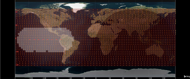
Band2_Ka field of view
You can also create applicable reports and graphs using the Figure Of Merit and the Report & Graph Manager.
Using the Deck Access tool
The Deck Access tool enables you to compute access to a set of objects (such as a subset of a Satellite Collection object), which are not currently defined within the scenario, from a single object within the scenario (such as a Sensor object). Deck access operations are useful when you have a large number of objects that no longer need to be in the STK scenario but for which you would like visibility information. Using deck access can greatly reduce load and save time for such scenarios and minimize graphical clutter. In this case, you will use the Deck Access tool with a tracking station's sensor.
Inserting a tracking station
A tracking station will track your satellites.
- Insert a Place (
 ) object using the Insert Default () method.
 - Rename Place1 () TrackingStation.
Inserting a tracking station sensor
The tracking station uses a sensor to track satellites.
- Insert a Sensor object using the Insert Default method.
- Select TrackingStation () in the Select Object dialog box.
- Click to close the Select Object dialog box.
- Rename Sensor2 () SensorFoR.
FoR stands for field of regard.
Modeling Complex Conic sensor patterns
Use a Complex Conic sensor pattern for the tracking station's FoR. Complex Conic sensor patterns are defined by the inner and outer half angles and minimum and maximum clock angles of the sensor's cone.
- Open SensorFoR's () Properties ().
- Select the Basic - Definition page.
- Open the Sensor Type drop-down list.
- Select Complex Conic.
- Enter 180 deg in the Half Angles - Outer field in the Complex Conic panel.
- Click to accept your changes and to keep the Properties Browser open.
Constraining the sensor's field of regard
- Select the Constraints - Active page.
- Click Add new constraints (
 ) in the Active Constraints toolbar.
 - Select Range in the Constraint Name list in the Select Constraints to Add dialog box.
- Click .
- Click to close the Select Constraints to Add dialog box.
- Select the Max check box in the Range panel.
- Enter 2500 km in the Max field.
- Click to accept your changes and to keep the Properties Browser open.
Setting 2D Graphics attributes
The 2D Graphics attributes answer three basic questions about an STK object:
- What do you want to show?
- How do you want it to look?
- When do you want it to be seen?
Update the sensor's 2D Graphics attributes to change its color to gray.
- Select the 2D Graphics - Attributes page.
- Open the Color drop-down llist.
- Select gray (the first color on the bottom row).
- Click to accept your changes and to keep the Properties Browser open.
Setting 3D Graphics attributes
Use the 3D Graphics - Attributes page to control the display of a sensor in the 3D graphics window.
- Select the 3D Graphics - Attributes page.
- Enter the value 70 in the % Translucency field in the Projection panel.
- Click to accept your changes and to close the Properties Browser.
Opening the Deck Access tool
Open the Deck Access tool with SensorFoR.
- Right-click on SensorFoR () in the Object Browser.
- Select Deck Access... (
 ) in the shortcut menu.
Selecting the target deck
Indicate the type of object that is defined by the data in the specified file.
- Open the Type drop-down list in the Select Target Deck panel once the Deck Access tool opens.
- Select Collection Subset.
- Open the Name drop-down list
- Select Custom_OrbitElems.AllSatellites.
- Note that the Create Report option in the Data panel is selected by default.
- Click to generate deck access results.
- View the Deck Access for SensorFoR - DeckAccess report when it opens.
- Close the report once you are done.
- Click to close the Deck Access tool
All of the subsets from the Satellite Collection objects are located here.
The STK software will present the results in a report window. The format is defined by the
The report shows you accesses to each satellite from the tracking station sensor over your analysis period.
Using routing files
You can use a routing file to specify the rules for links in a chain associated with objects in a constellation or entries in a satellite collection subset. A routing file is an ASCII text file with a *.routing extension that the STK software reads every time it computes a chain with the constellation or subset.
Creating a new routing file
Create a new routing file to specify multihop rules for your the satellite collection. Multihop rules, introduced in version 12.5 of the STK software, govern the links between two or more objects within the constellation or between two or more entries within a subset. Multihop rules do not apply to objects outside of the constellation or subset.
- Return to your text editor.
- Copy and paste the following into a blank page in the text editor.
- Open the File menu.
- Select Save As....
- Select All Files as the Save as type.
- Browse to your Scenario folder
- Change the File name to Rules.routing.
- Click .
- Close your text editor.
Begin MultihopRules
DefaultRule Never

Begin Rules
Access "CollectionSubsetEntry SatelliteCollection/Custom_OrbitElems/Subset/AllSatellites S1_P1_S1" "CollectionSubsetEntry SatelliteCollection/Custom_OrbitElems/Subset/AllSatellites S1_P2_S1" reciprocal
Access "CollectionSubsetEntry SatelliteCollection/Custom_OrbitElems/Subset/AllSatellites S1_P2_S1" "CollectionSubsetEntry SatelliteCollection/Custom_OrbitElems/Subset/AllSatellites S1_P3_S1" reciprocal
Access "CollectionSubsetEntry SatelliteCollection/Custom_OrbitElems/Subset/AllSatellites S1_P3_S1" "CollectionSubsetEntry SatelliteCollection/Custom_OrbitElems/Subset/AllSatellites S1_P4_S1" reciprocal
Access "CollectionSubsetEntry SatelliteCollection/Custom_OrbitElems/Subset/AllSatellites S1_P4_S1" "CollectionSubsetEntry SatelliteCollection/Custom_OrbitElems/Subset/AllSatellites S1_P5_S1" reciprocal
Access "CollectionSubsetEntry SatelliteCollection/Custom_OrbitElems/Subset/AllSatellites S1_P5_S1" "CollectionSubsetEntry SatelliteCollection/Custom_OrbitElems/Subset/AllSatellites S1_P6_S1" reciprocal
Access "CollectionSubsetEntry SatelliteCollection/Custom_OrbitElems/Subset/AllSatellites S1_P6_S1" "CollectionSubsetEntry SatelliteCollection/Custom_OrbitElems/Subset/AllSatellites S1_P7_S1" reciprocal
Access "CollectionSubsetEntry SatelliteCollection/Custom_OrbitElems/Subset/AllSatellites S1_P7_S1" "CollectionSubsetEntry SatelliteCollection/Custom_OrbitElems/Subset/AllSatellites S1_P8_S1" reciprocal
End Rules
End MultihopRules
The multihop section must specify both sides of the link: the from (outgoing) and to (incoming) sides. In this example, looking at the first access line, the satellite in orbital plane 1 can only talk to the adjacent satellite in orbital plane 2. The next access, the satellite in orbit plane 2 can only talk to the satellite in orbit plane 3, etc. At the end of each access is reciprocal, which simply means the data can flow in both directions.
Inserting a receiving station
You will use the routing file to model a multihop communications link to a receiving station, located in West Africa.
- Insert a Place () object using the Insert Default () method.
- Rename Place2 () ReceivingSatation.
- Open ReceivingStation's () Properties ().
- Select the Basic - Position page.
- Set the following in the Position panel:
- Click to accept your changes and to close the Properties Browser.
| Option | Value |
|---|---|
| Latitude | 21.5353 deg |
| Longitude | -16.4078 deg |
Applying multihop rules to a Satellite Collection object
Use the Rules.routing file to define the satellite collection's routing.
- Open Custom_OrbitElems' () Properties ().
- Select the Basic - Routing page.
- Select the Use routing file check box.
- Click the Use routing file ellipsis (
 ).
). - Select the STK User folder in the navigation pane.
- Select the SatelliteCollection Scenario folder.
- Click .
- Select Rules.routing.
- Click .
- Click to accept your changes and to close the Properties Browser.
Creating a Chain object
A ![]() ) collection, and then reroute data to any other satellites in the collection and then to the receiving station.
) collection, and then reroute data to any other satellites in the collection and then to the receiving station.
- Insert a Chain (
 ) object using the Insert Default () method.
 - Rename Chain1 () RoutedChain.
Defining the start and end objects
Start by choosing the start object and end object in your chain.
- Open RoutedChain's () Properties ().
- Select the Basic - Definition page when the Properties Browser opens.
- Click the Start Object ellipsis ().
- Select SensorFoR () in the Select Object dialog box.
- Click to close the Select Object dialog box.
- Click the End Object ellipsis ().
- Select ReceivingStation () in the Select Object dialog box.
- Click to close the Select Object dialog box.
- Keep the Properties Browser open.
Creating the Chain object's first connection
After you choose the start and end objects in your chain, you need to build the chain's connections. The first connection is from the tracking station's field of regard to the satellites in the Custom_OrbitElems (![]() ) collection.
) collection.
- Click in the Connections panel.
- Click the From Object ellipsis ().
- Select SensorFoR () in the Select Object dialog box.
- Click to close the Select Object dialog box.
- Click the To Object ellipsis ().
- Select Custom_OrbitElems () - AllSatellites () in the Select Object dialog box.
- Click to close the Select Object dialog box.
Creating the Chain Object's second connection
Next, build the second connection from the Custom_OrbitElems (![]() ) collection to any other satellites in the collection.
) collection to any other satellites in the collection.
- Click in the Connections panel.
- Click the From Object ellipsis ().
- Select Custom_OrbitElems () - AllSatellites () in the Select Object dialog box.
- Click to close the Select Object dialog box.
- Click the To Object ellipsis ().
- Select Custom_OrbitElems () - AllSatellites () in the Select Object dialog box.
- Click to close the Select Object dialog box.
Creating the Chain Object's final connection
Now build the third connection from the Custom_OrbitElems (![]() ) collection to the receiving station.
) collection to the receiving station.
- Click in the Connections panel.
- Click the From Object ellipsis ().
- Select Custom_OrbitElems () - AllSatellites () in the Select Object dialog box.
- Click to close the Select Object dialog box.
- Click the To Object ellipsis ().
- Select ReceivingStation () in the Select Object dialog box.
- Click to close the Select Object dialog box.
- Click to accept your changes and to close the Properties Browser.
Computing the Chain object's accesses
- Select RoutedChain () in the Object Browser.
- Open the Chain menu.
- Select Compute Accesses.
Generating a Complete Chain Access report
A
- Right-click on RoutedChain () in the Object Browser.
- Select Report & Graph Manager... (
 ) in the shortcut menu.
 - Select the Complete Chain Access (
 ) report in the Installed Styles () folder once the Report & Graph Manager opens.
 - Click
- View the data in the report to determine when complete chain accesses occur during your scenario.
- Close the report and the Report & Graph Manager once you are done.
Displaying accesses in the Timeline View
With the Timeline View, you can visualize a variety of time intervals within your scenario.
- Click Add Time Components (
 ) in the Timeline toolbar.
 - Select RoutedChain () in the Objects list once the Select Timeline Component dialog box opens.
- Select CompleteChainAccessIntervals (
 ) in the Components for: RoutedChain list.
 - Click to accept your changes and to close the Select Timeline Component dialog box.
- Look at the Timeline View.
You can see when complete chain accesses are taking place during your scenario.
Viewing the complete chain access intervals in the 3D Graphics window
You can visualize the exact moment when Chain object's accesses take place in the 3D Graphics window.
- Bring the 3D Graphics window to the front.
- Move the gray pointer (
 ) in the Timeline View until it's over the first access.
 - Continue moving the gray pointer () to view additional accesses.
- Click Reset () in the Animation toolbar once you are done.

COMPLETE CHAIN ACCESS INTERVAL
In this example, one satellite in the Satellite Collection Object passes through the tracking station sensor's field of regard. There is an access between the sensor and that satellite. That satellite then passes data to the satellite in the adjacent orbital plane which can access the receiving station and passes data to the receiving station.
Saving your work
Clean up your workspace and save your work.
- Close any open reports, properties and tools.
- Save () your work.
Summary
This was a comprehensive scenario that covered multiple ways to use the Satellite Collection object. You learned the following:
- How to create a Walker-type satellite collection
- How to use a database search to select satellites to use in a Satellite Collection object
- How to use custom orbit definition files to:
- Create a collection of satellites using the OrbitElements content type
- Create a collection of satellites using the SSC content type and adding metadata
- Add additional metadata using the Metadata content type
- How to build and use a reference object
- How to use the Deck Access Tool to track satellites in a Satellite Collect object
- How to create a routing file and use it in a Chain object