STK Premium (Space) or STK Enterprise
You can obtain the necessary licenses for this tutorial by contacting AGI Support at support@agi.com or 1-800-924-7244.
This lesson requires STK 12.4 or newer to complete because it includes new features introduced in STK 12.4. If interested, please contact AGI Support at support@agi.com.
The results of the tutorial may vary depending on the user settings and data enabled (online operations, terrain server, dynamic Earth data, etc.). It is acceptable to have different results.
Capabilities Covered
This lesson covers the following STK Capabilities:
- STK Pro
- STK SatPro
- Coverage
- Conjunction Analysis
- Communications
Problem Statement
You are designing an upcoming satellite trailing formation. There are many factors to consider and you are curious about the potential impact of a future launch. With Space Situational Awareness (SSA) in mind, you want to consider factors such as providing a global presence, while also mitigating potential collisions and signal interference.
In this lesson you will:
- Create a trailing formation of 440 satellites
- Verify that there is global coverage
- Model nearby satellites and objects in orbit
- Calculate potential conjunctions
- Assess communication interference
Solution
Use STK 12.4 or newer to build the components needed to understand the problem and find a solution. The Satellite Collection object can be used to represent an entire constellation of satellites in a single scenario. Providing basic visualization, a minimal memory footprint and efficient save and load operations, Satellite Collections can be used in standard STK capabilities and tools such as Coverage, Conjunction Assessment, Deck Access and Communications. In this tutorial, you will model a large satellite collection and calculate various factors that quantify its impact and its success.
What You Will Learn
Upon completion of this tutorial, you will be able to:
- Build large constellations
- Analyze large constellations in coverage calculations
- Analyze large constellations for satellite conjunctions
- Measure the communication interference
Video Guidance
Watch the following video. Then follow the steps below, which incorporate the systems and missions you work on (sample inputs provided).
Create a New Scenario
Create a new scenario.
- Launch STK (
 ).
). - In the Welcome to STK window, click Create a Scenario (
 ).
). - Enter the following in the New Scenario Wizard:
- When finished, click .
- When the scenario loads, click Save (
 ). A folder with the same name as your scenario is created for you in the location specified above.
 - Verify the scenario name and location.
- Click .
| Option | Value |
|---|---|
| Name: | LargeConstellation |
| Location: | Default |
| Start: | Default |
| Stop: | Default |
The results of this study may vary due to varying scenario times.
Save Often!
Seed Satellite
Your mission is to build and understand the impacts of a large satellite collection. You'll build this up in steps so you can understand each component. The first step is to build a large satellite collection. The best practice for working with satellite collection objects is to:
- Build the seed satellite
- Model the satellite's payloads
- Load the seed satellite into a satellite collection
This allows you to define the orbital parameters of the collection in the seed, functioning as a template. The seed satellite will also model your payloads which you will use later in the study.
Create Seed Satellite
Insert the seed satellite.
- Select Satellite (
 ) in the Insert STK Objects tool.
 - Select the Orbit Wizard (
 ) method.
 - Click .
- Set the following on the Orbit Wizard:
- Leave all other options as the default values.
- Click .
| Option | Value |
|---|---|
| Type: | Repeating Ground Trace |
| Satellite Name: | SeedSatellite |
| Approximate Altitude: | 700 km |
| Inclination: | 70 deg |
Create Seed Transmitter
Our first payload will be a transmitter. For this example, you will use the default parameters.
- Select Transmitter (
 ) in the Insert STK Objects tool.
 - Select the Insert Default () method.
- Click .
- Select SeedSatellite () on the Select Object window.
- Click .
- Right-click on Transmitter1 ().
- Select Rename.
- Rename Transmitter1 () SimpleTx.
Create Seed Sensor
Our next payload is a sensor, you will make some changes to it's field of view. First, insert the Sensor on SeedSatellite (![]() ).
).
- Select Sensor (
 ) in the Insert STK Objects tool.
 - Select the Define Properties (
 ) method.
 - Click .
- Select SeedSatellite () on the Select Object window.
- Click .
Change the Sensor's Field Of View
- Select the Basic - Definition page.
- Set the following: set the Sensor Type to Rectangular with a Vertical Half Angle of 10 deg and a Horizontal Half Angle of 15 deg.
- Click .
- Right-click on Sensor1 ().
- Select Rename.
- Rename Sensor1 () EarthImaging.
| Option | Value |
|---|---|
| Sensor Type: | Rectangular |
| Vertical Half Angle: | 10 deg |
| Horizontal Half Angle: | 15 deg |
Satellite Collection
The Satellite Collection (![]() ) object allow us to model the entire collection of satellites into a single entity. Use the seed satellite, defined earlier in this lesson, to model it's orbit and it's payloads.
) object allow us to model the entire collection of satellites into a single entity. Use the seed satellite, defined earlier in this lesson, to model it's orbit and it's payloads.
Add Satellite Collection Object to Insert STK Objects tool
Ensure the SatelliteCollection (![]() ) object appears in the Insert STK Objects tool.
) object appears in the Insert STK Objects tool.
- Click on the Insert STK Objects tool.
- In the New Object list, select the object you want to add.
- Click .
Insert the Satellite Collection
Insert a SatelliteCollection (![]() ) object. This will represent the upcoming satellite constellation. The SatelliteCollection object will model a Trailing Formation of two sets of 220 satellites. These will be in a circular orbit (eccentricity of 0) at an inclination of 70 deg. The satellites will be in a Low Earth Orbit (LEO) at an altitude of 700 km (or Semi-Major Axis of 6808.23 km). These are the same properties you defined in the SeedSatellite (
) object. This will represent the upcoming satellite constellation. The SatelliteCollection object will model a Trailing Formation of two sets of 220 satellites. These will be in a circular orbit (eccentricity of 0) at an inclination of 70 deg. The satellites will be in a Low Earth Orbit (LEO) at an altitude of 700 km (or Semi-Major Axis of 6808.23 km). These are the same properties you defined in the SeedSatellite (![]() ).
).
- Select SatelliteCollection (
 ) in the Insert STK Objects tool.
 - Select the Walker Tool () method.
- Click .
- In the Walker Tool window set the following:
- Click .
- Click
| Property | Value |
|---|---|
| Seed Satellite | SeedSatellite |
| Number of Sats per Plane | 220 |
| Number of Planes | 2 |
| Container Options - Select Option | Create Satellite Collection |
| Create new Satellite Collection - Name | ProposedSats |
View the Satellites
By default the visualization of the collection is turned off. Turn on the visuals to display the satellites in the collection on the 2D and 3D Graphics windows.
- Right-click on ProposedSats () in the Object Browser.
- Select Properties ().
- Select the Graphics - Attributes page.
- Select the Show option.
- Select Show in the AllSatellites subset row.
- Click to accept the changes.
- Clear the box next to SeedSatellite () in the Object Browser. You don't need to visualize it.
This enables you to see the collection in the 2D and 3D Graphics windows.

Satellite Collection in 3D Graphics Window
Load in Payloads
Our Seed Satellite has two payloads, the transmitter and the imager. Load that into the satellite collection.
- Return to the ProposedSats' () Properties Browser.
- Select the Basic - Definition page.
- Click Edit Default Subset Reference Object (
 ) in the Default Subset Reference Object (optional) section.
 - Select SeedSatellite ().
- Click .
- Click to accept the changes and close the Properties Browser.
Coverage Analysis
Now that the satellites have been modeled in the scenario, you can begin to understand the scope of this mission. Run a coverage analysis to confirm a global presence. You want to make sure that the satellites are able to image the globe. Remember that the inclination is set to 70 deg, so we have chosen not to focus on the poles, but the more populated centers away from them.
Insert a Coverage Definition
First you will insert a Coverage Definition object.
- Select Coverage Definition (
 ) in the Insert STK Objects tool.
 - Select the Define Properties () method.
- Click .
- Rename the Coverage Definition () Globe.
Define the Coverage Definition
Now let's define the Coverage Definition's grid and assets.
- Select the Basic - Grid page.
- Set the Type to Global under Grid Area of Interest.
- Select the Basic - Assets page.
- Select AllSensors in the Assets list.
- Click .
- Click .
Compute Coverage
Your Coverage Definition is defined, so now you can compute coverage.
- Right-click on Globe () in the Object Browser.
- Select CoverageDefinition.
- Select Compute Accesses.
Figure of Merit
The metric you'll use to quantify coverage is a Figure of Merit. You will calculate the Revisit Time as it measures the intervals during which coverage is not provided (also known as “the gaps”). If a grid point is accessible at the current time, the gap duration is computed as zero, meaning there is no gap. This will tell us how often we can image a region and where we have no chance of imaging the ground.
Insert a Figure of Merit
First you will insert a Figure of Merit object.
- Select Figure Of Merit (
 ) in the Insert STK Objects tool.
 - Select the Define Properties () method.
- Click .
- Select Globe () in the Select Object window.
- Click .
- Rename the Figure of Merit () Gaps.
Define the Figure of Merit
Now let's define the Figure of Merit to calculate Revisit Time.
- Select the Basic - Definition page.
- Set the Type to Revisit Time in the Definition section.
- Leave Compute set to Maximum. Since you're looking at the "gaps", the maximum computed static value is the duration of the longest gap in the coverage over the entire coverage interval.
Display the Figure of Merit
You want to display the revisit time while animating, so set up the figure of Merit animation graphics.
- Select the 2D Graphics - Static page.
- Clear Show Static Graphics.
- Select the 2D Graphics - Animation page.
- Set the Accumulation - Show to Up to current time.
- Locate the Display Metric section
- Select Show Contours.
- Set the Levels:
Option Value Start 0 sec Stop 86400 sec Step 3600 sec - Click .
- Change the Color Ramp to go from Blue to Red.
- Select Natural Neighbor for the Contour Interpolation.
- Click .
This will show the coverage over the entire day (24 hrs or 86400 sec).
Animate the Scenario
Animate your scenario and observe the how the coverage changes over time. Your satellites have an inclination of 70 degrees, which means that they have good coverage over the more populated areas and you can see how often those regions get imaged.
- Click animate (
 ) the scenario.
 - Observe the gap time (reflected in the changing colors).
- Reset (
 ) the animation when done.

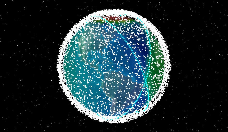
Revisit Time
Model Objects in Orbit
When designing a mission, it's essential to know what objects are nearby and where they are located. We modeled our ProposedSats in LEO orbit, let's see what else is in orbit in that space. We'll model another satellite collection object, but this time we'll load in existing objects in orbit. The satellite collection capability allows us to model both our proposed satellites and existing satellites.
Use a Local Satellite Database
When using a local satellite database, it's a good idea to obtain current data. You must be connected to the Internet to utilize this source.
- Open LargeConstellation's () properties ().
- Select the Basic - Database page.
- Ensure Database Type: is set to Satellite.
- Click .
Update Satellite Database
Update Database obtains the latest satellite database information from the AGI satellite database server.
- Click in the Update Satellite Database window.
- When the Information window appears, click .
- Click to close the Update Satellite Database window.
- Click to close LargeConstellation' () properties ().
Insert the Satellite Collection
Insert a Satellite Collection (![]() ) object that will represent existing objects in LEO orbit.
) object that will represent existing objects in LEO orbit.
- Select SatelliteCollection () in the Insert STK Objects tool.
- Select the Define Properties () method.
- Click .
- Rename the new SatelliteCollection () object LEOSats.
- Select the Basic - Definition page.
- Set the Type to Database.
Add LEO Satellites in Orbit
Search the Database to add LEO satellites that at some point, are within 800 km in altitude, have a shorter period, and are not just active satellites.
- Click .under Database Search.
- Click in the bottom left in the Database Search window. The default search is objects in GEO. We want to look at objects in LEO for our mission.
- Click in the top of the window.
- Set the Out-of-Data Duration (Days) to 300.
- Click .
- Set the following search parameters:
Parameter Value Periapsis Altitude - Max 800 km Apoapsis Altitude - Max 800 km Period - Max 14400.0 min Operational Status Active, Inactive, Unknown - Click ..
- Review some of the objects that appear in the search, you should see a variety of objects, including debris (DEB) and inactive or unknown statuses for satellites.
- Click .
- Click .
View the Satellites
Like before, by default the visualization of the collection is turned off. Turn on the visuals to display the satellites in the collection on the 2D and 3D Graphics windows.
- Select the Graphics - Attributes page .
- Select the Show option.
- Select Show in the AllSatellites subset row.
- Click to accept the changes. This enables you to see the collection in the 2D and 3D Graphics windows.
- Clear the Show option for the LEOSats in the Object Browser to clean up your view.
This is a quick way to view all the neighboring objects we need to consider before placing our satellites in orbit. We can refine this analysis further by considering the objects we may have conjunctions with. We'll look at that in the next section.
Insert the AdvCat
With the proposed satellites modeled, global coverage verified, and nearby orbiting objects modeled, next you will examine the number of assets that may have conjunctions with your satellites. You will use the Advanced Conjunction Analysis Tool to conduct this study.
You may need to add the Advanced CAT object to the Insert STK Objects tool. To do this, click the Edit Preferences button and select it from the New Object tool.
Add AdvCAT Object to Insert STK Objects tool
Ensure AdvCAT (![]() ) appears in the Insert STK Objects tool.
) appears in the Insert STK Objects tool.
- Click on the Insert STK Objects tool.
- In the New Object list, select the object you want to add.
- Click .
Insert the AdvCAT Object
First insert the AdvCAT object.
- Select AdvCAT (
 ) in the Insert STK Objects tool.
 - Select the Define Properties () method.
- Click .
- Rename AdvCAT1 to Conjunctions.
Define the AdvCAT Object
Set up the properties of the AdvCAT object. This will calculate the potential conjunctions that your proposed satellites may cause.
- Select the Basic - Main page.
- Select ProposedSats-AllSatellites in the Primary List section. The rest of the objects in orbit will be compared against these satellites.
- Click Move (
 ) to add it to the Chosen list.
 - Select stkAllTLE.tce in the Secondary List. This is the entire public catalog of tracked space objects.
- Click Move () to add it to the Chosen list.
- Select Display Acknowledgment when done. This will display a message when the computation is complete.
- Click in the AdvCAT object's Properties, Basic - Main page to compute the conjunctions.
- Click .
- Reset () on the animation toolbar to view the error ellipsoids in the 3D Graphics window. All the green points correspond to objects from the public catalog of tracked space objects.
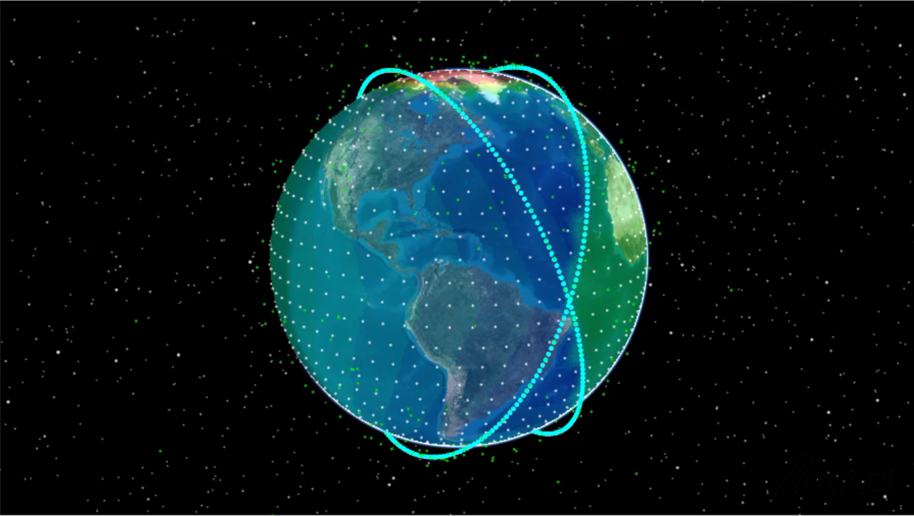
Error Ellipsoids in 3D Graphics window
Understand the Conjunctions
The green ellipsoids represent objects in orbit that your proposed satellites have conjunctions with. Let's look at this in more detail.
- Right-click on Conjunctions () in the Object Browser.
- Select Report & Graph Manager (
 ).
). - Expand (
 ) Installed Styles folder in the Styles list.
 - Select Close Approach by Min Sep. This report will display the conjunctions sorted by minimum separation.
- Click .
- Take a look at the report to see if any of your satellites will interact with other space objects.
For each satellite in the collection, the report tells you which space objects will interact with it. The space objects are listed by the Object Name (the space surveillance catalog number), it's time in and out, the minimum separation of the ellipsoids, and the minimum range of each object.
Impact on Communication Links
Our proposed satellites provide coverage and interact with other objects in orbit. How else will your proposed satellites affect nearby systems? Let's address the interference this new set of satellites will have on a communication link. You'll model a simple space to ground system to understand the impact. Satellite Collection objects can be utilized as Interference objects within the communication system analysis.
Create Ground Site
Insert a place object to function as the receiver site. We'll use the default properties.
- Select Place (
 ) in the Insert STK Objects tool.
 - Select the Insert Default () method.
- Click .
- Right-click on Place1 () in the Object Browser.
- Select Rename.
- Rename Place1 () Receiver_Site.
Create Ground Receiver
Insert a receiver object. We'll use the default properties.
- Select Receiver (
 ) in the Insert STK Objects tool.
 - Select the Insert Default () method.
- Click .
- Select Receiver_Site () on the Select Object window.
- Click .
- Rename Receiver1 () Rcvr.
Create a New Satellite
Insert a satellite object and make some changes to it's orbit.
- Select Satellite () in the Insert STK Objects tool.
- Select the Define Properties () method.
- Click .
- Set the Inclination to 45 deg.
- Click .
- Rename the Satellite () Space_Neighbor.
Create Transmitter on the Satellite
Insert a transmitter object to go on the satellite. You will use the default properties.
- Select Transmitter () in the Insert STK Objects tool.
- Select the Insert Default () method.
- Click .
- Place it on Space_Neighbor ().
- Rename Transmitter1 () to Tx.
Insert Constellation Objects
Insert two Constellation Objects, one for the transmitters and one for the receiver. These will be used to define the communication assets in the CommSystem Object.
- Select Constellation (
 ) in the Insert STK Objects tool.
 - Select the Insert Default () method.
- Click .
- Repeat the above steps once to insert a second Constellation ().You should have a total of two new Constellation objects in the Object Browser.
- Rename the new Constellation objects Transmitter and Receiver.
Define Transmitter Constellation
Add Space_Neighbor's transmitter to the Transmitter constellation.
- Right-click on Transmitter () in the Object Browser.
- Select Properties ().
- Select the Basic - Definition page.
- Select Tx () in the Available Objects list.
- Click Move () to move it to the Assigned Objects list.
- Click .
Define Receiver Constellation
Add Receiver_Site's receiver to the Receiver constellation.
- Right-click on Receiver () in the Object Browser.
- Select Properties ().
- Select the Basic - Definition page.
- Select Rcvr () in the Available Objects list.
- Click Move () to move it to the Assigned Objects list.
- Click .
Set Up the CommSystem Object
To set up a CommSystem (![]() ) object models dynamically configured communications links between constellations of transmitters and receivers.
) object models dynamically configured communications links between constellations of transmitters and receivers.
Set up the CommSystem object focusing on the following:
- Transmit: Select the transmitter constellation () to carry out the transmit function in the communications link analysis.
- Receive: Select the receiver constellation () to carry out the receive function in the CommSystem.
- Interference: Select the interference constellation () to calculate the effect of interference.
- Link Definition: Select the link criteria and specify whether the selected criterion is to constrain the receiving or transmitting constellations in the CommSystem.
- Interval: Specify the time period and step size for the CommSystem.
Add CommSystem Object to Insert STK Objects tool
Ensure the CommSystem (![]() ) object appears in the Insert STK Objects tool.
) object appears in the Insert STK Objects tool.
- Click on the Insert STK Objects tool.
- In the New Object list, select the object you want to add.
- Click .
Insert a CommSystem Object
Insert a CommSystem (![]() ) object into your scenario.
) object into your scenario.
- Select CommSystem (
 ) in the Insert STK Objects tool.
 - Select the Define Properties () method.
- Click .
- Rename CommSystem1 () CommSystem.
Set CommSystem's Transmit Function
Select the Transmitters (![]() ) constellation to carry out the transmit function in the system.
) constellation to carry out the transmit function in the system.
- Select the Basic - Transmit page.
- Select Transmitter () in the Available Constellations list.
- Click Move () to move it to the Assigned Constellations list.
- Click .
Set CommSystem's Receive Function
Select the Receiver (![]() ) constellation to carry out the receive function in the system.
) constellation to carry out the receive function in the system.
- Select the Basic - Receive page.
- Select Receiver () in the Available Constellations list.
- Click Move () to move it to the Assigned Constellations list.
- Click .
Set CommSystem's Interference Function
Select the ProposedSats/AllTransmitters to carry out the interference function in the system.
- Select the Basic - Interference page.
- Select ProposedSats/AllTransmitters in the Available Constellations list.
- Click Move () to move it to the Assigned Constellations list.
- Click .
Calculate Interference
You are now ready to calculate interference.
- Save () your scenario.
- Right click on CommSystem () in the Object Browser.
- Select CommSystem.
- Select Compute Data.
There is a calculation progress bar in the lower right corner of STK.
Determine Interference
Determine if the communication link between Space_Neighbor and Receiver_Site contains interference.
- Right-click on CommSystem () in the Object Browser when the calculation is complete.
- Select Report & Graph Manager... ().
- Select Link Information Detailed (
 ) in the Installed Styles folder.
 - Click .
- Locate the BER and BER+I columns. BER+I is Bit Error Rate plus Interference.
- Scroll down through the report and compare both columns. You can see that there is an impact to the communication link by your large satellite collection. Results may differ depending on your scenario time.
- You can see in the detailed link budget report the Bit Error Rate without and with interference. Jump to a time where there is an affect from the interference.

BER and BER + Interference from the Link Information Detailed Report
In the scenario you can see how the signal is affected when the proposed satellite collection and the Space_Neighbor are close to one another and overhead of the ground site. You see both in the data and in the display that there is an impact to neighboring commutation links with this proposed satellite configuration.
Save Your Work
- Close any reports and/or tools you still have open.
- Save () your work.
Summary
Review what you have modeled and calculated in your mission. You have successfully modeled a large network of satellites. These satellites had sensors attached which you used to calculate coverage. With all these new objects in orbit, you also calculated the number of space objects that will potentially interact with the collection. Finally, using the transmitters on your satellite collection, you modeled the interference impact that this collection of satellites has on other communication links.
On Your Own
The question now is how successful the mission will be with all the potential conjunctions and comm interference. Now that you have quantified these topics, the next step is to consider ways to adapt the mission. Determine what is important in your mission. Is the orbit or the number of satellites something you can change? Can you use a different transmit frequency? With STK, users can adapt their mission while still maintaining a cohesive digital thread.