STK Pro, STK Premium (Air), STK Premium (Space), or STK Enterprise
You can obtain the necessary licenses for this tutorial by contacting AGI Support at support@agi.com or 1-800-924-7244.
The results of the tutorial may vary depending on the user settings and data enabled (online operations, terrain server, dynamic Earth data, etc.). It is acceptable to have different results.
Capabilities covered
This lesson covers the following capability of the Ansys Systems Tool Kit® (STK®) digital mission engineering software:
- STK Pro
Problem statement
Engineers and operators require a quick way to populate the central body of their STK application's 3D Graphics window with imagery, terrain, data sets, and tile sets. Furthermore, they require the ability to manage how and when these items are displayed. In this lesson, you will insert, organize, and manage imagery and terrain for Mt. St. Helens. You will export and import a base globe. You will add a KMZ file for the Tioga West Rim Trail, and import this as an STK object. Lastly, you will insert a 3D Tileset that shows the AGI headquarters.
Solution
Using STK Pro and the Globe Manager, first you will organize imagery and terrain items into sets. Then, you will toggle the display of individual imagery and terrain items or sets of items.
What you will learn
Upon completion of this tutorial, you will have a basic understanding of:
- Globe Manager
- Image Files
- Terrain Files
- 3D Tilesets
Video guidance
Watch the following video. Then follow the steps below, which incorporate the systems and missions you work on (sample inputs provided).
Creating a new scenario
Create a new scenario.
- Launch the STK application (
 ).
). - In the Welcome to STK window, click Create a Scenario.
- Enter the following in the New Scenario Wizard:
- When you finish, click .
- When the scenario loads, click Save (
 ). A folder with the same name as your scenario is created for you in the location specified above.
 - Verify the scenario name and location.
- Click .
| Option | Value |
|---|---|
| Name | STK_Globe_Manager |
| Location | C:\Users\<username>\Documents\STK_ODTK 13 |
| Start | Accept default Day/Month/Year. Change time to 18:00:00.000 |
| End | Accept default Day/Month/Year. Change time to 18:00:00.000 |
Organizing your workspace
Let's take a moment to organize the STK workspace.
- Close (
 ) the Insert STK Objects Tool.
 - Close () the 2D Graphics window.
- Maximize (
 ) the 3D Graphics window.
 - Close () the Timeline View.
Disabling terrain server
You're using local files for now. Turn off Terrain Server.
- Open STK_Globe_Manager's (
 ) Properties (
 ).
). - Select the Basic - Terrain page.
- Clear Use terrain server for analysis.
- Click to accept the changes and close the Properties Browser.
Adding and managing terrain and imagery
You can use Globe Manager to access imagery and terrain data items from local drives and external sources such as Bing Maps and Cesium Ion.
- Click Globe Manager (
 ) in the Globe Manager Toolbar (
 ) found at the top of the 3D Graphics Window to open the Globe Manager.
The Globe Manager opens and displays the Hierarchy window and its associated toolbar. If all of the buttons are not visible, you may have to expand the Globe Manager pane. Some toolbar options are grayed out depending on what is selected in the Globe Manager.
Creating a Terrain / Imagery set
A Terrain / Imagery Set is a group folder used for organizing terrain and imagery files.
- Select Earth (
 ) in the Globe Manager.
 - Click Add Terrain/Imagery (
 ) on the Globe Manager toolbar.
 - Click Add Terrain/Imagery Set (
 ) to create a new set.
 - Change Name: to St Helens in Globe Manager: Set Properties window.
- Click .
Adding terrain and imagery
Add terrain and imagery to the set.
- Right-click on St Helens (
 ) in the Globe Manager.
 - Select Add Terrain/Imagery to Set.
- Set Path to <Install Dir>\STKData\VO\Textures in the Globe Manager: Add Terrain and Imagery Data window. This will display all the available STK textures in that folder.
- Select St Helens.jp2.
- Click .
Zooming to Mount St. Helens
View St Helens.jp2 in the 3D Graphics window.
- Expand (
 ) St. Helens () in the Globe Manager.
 - Select St Helens.jp2 (
 ).
). - Click Zoom To (
 ) in the Globe Manager toolbar. The image of Mount St. Helens displays in the 3D Graphics window.
 - Clear the check box next to St Helens.jp2 to turn its visibility off.
- Select the check box to show the image again.
Toggling the extents of the imagery file
Toggle Extents displays the range and borders of the selected item on a central body.
- Ensure St Helens.jp2 () is selected in the Globe Manager.
- Click Toggle Extents (
 ) in the Globe Manager toolbar. The image of Mount St. Helens is highlighted in green, showing the extent of the image.
 - Click Toggle Extents () to remove the highlight.
Adding a PDTT file to Globe Manager
An STK Terrain File (pdtt) is a terrain file converted from a local terrain file such as a USGS Digital Elevation Model (DEM) or NIMA/NGA DTED. A PDTT can be used both analytically and visually in STK.
- Right-click on the St Helens () set in the Globe Manager.
- Select Add Terrain/Imagery to Set.
- Set Path: to <Install Dir>\STKData\VO\Textures in the Globe Manager: Add Terrain and Imagery Data window.
- Select St Helens.pdtt.
- Click .
- Click on the Use Terrain for Analysis dialog box. This adds St Helens.pdtt to the Scenario () object's Basic - Terrain page as analytical terrain.
- In the 3D Graphics window, use your mouse to view Mount St. Helens. Note that outside of the St Helens.pdtt the surface is flat, and you are viewing the surface of the WGS84 Ellipsoid.
- In the Globe Manager, clear St Helens.pdtt (
 ) and St Helens.jp2 () to turn off visualization in the 3D Graphics window.
 - Select St Helens.pdtt () and St Helens.jp2 () to turn on visualization in the 3D Graphics window.

Mount St. Helens 3D Graphics Window View
Toggling the extents of the PDTT file
- Select St Helens.pdtt () in the Globe Manager.
- Click Toggle Extents () in the Globe Manager toolbar.St Helens.pdtt () will be highlighted in green, showing the extent of the pdtt.
- Click Toggle Extents () to remove the extents.
More information on the importation, conversion, and utilization of terrain and imagery files in STK can be found here.
Controlling the render order and transparency
- Select Earth () in the Globe Manager.
- Click Add Terrain/Imagery () on the Globe Manager toolbar.
- Select Add Terrain/Imagery (
 ).
). - In the Globe Manager: Open Terrain and Imagery Data window, click the ellipsis button (
 ) beside the Path: field.
 - Browse to <Install Dir>\Data\Resources\stktraining\imagery.
- Click .
- Select NPS_OrganPipeCactus_Map.pdttx and OrganPipeCactusNM_TerraColor_25m.jp2.
- Click .
Zooming to Organ Pipe Cactus National Monument
- SelectOrganPipeCactusNM_TerraColor_25m.jp2 () in the Globe Manager.
- Click Zoom To () on the Globe Manager toolbar.
You should notice that only a small part of the NPS_OrganPipeCactus_Map image is visible under the desert image.
Adjusting the render order
The Render Order window is used to prioritize the rendering order of images and terrain on the globe. This is useful when items overlap or are placed on top of other items.
- Select the Render Order tab in the Globe Manager.
- To bring the map image in front of the desert image, select OrganPipeCactusNM_TerraColor_25m.jp2 and drag it down over the top of NPS_OrganPipeCactus_Map.pdttx until a box appears around the NPS_OrganPipeCactus_Map file name.
- Release the file and you will see that in the 3D Graphics window it is now behind the map image.
The OrganPipeCactusNM_TerraColor_25m.jp2 file appears at the top of the Render Order list. Imagery and Terrain are rendered on the globe in the order they are added to the Globe Manager. Since OrganPipeCactusNM_TerraColor_25m.jp2 was the last image added, it is displayed as the top most item on the globe.
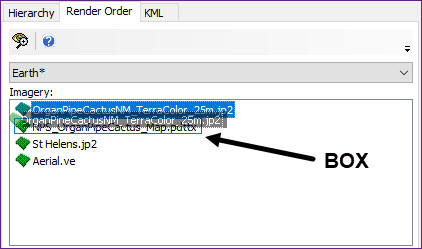
Render Order Box
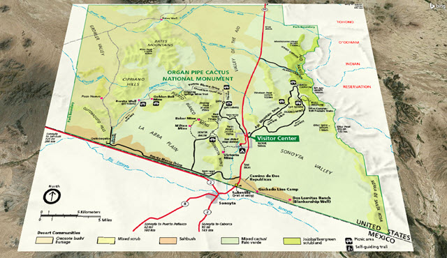
Organ Pipe Cactus Map
Setting the translucency
- Select the Hierarchy tab in the Globe Manager.
- Right-click on NPS_OrganPipeCactus_Map.pdttx ().
- Select Properties ().
- Set Translucency: value to 35 in the Globe Manager: Item Properties window Translucency Settings section.
- Click . The map graphic is now translucent and the desert imagery below it shows through.
Adding a new Terrain / Imagery Set
- Right-click on Earth () in the Globe Manager.
- Select Create Terrain/Imagery Set ().
- Change Name: to Organ Pipe in Globe Manager: Set Properties window.
- Click .
- Select NPS_OrganPipeCactus_Map.pdttx and OrganPipeCactusNM_TerraColor_25m.jp2 and drag them to the Organ Pipe () set in the Globe Manager.
You may notice in the 3D Graphics window that the map image has again fallen below the desert image. This can occur when moving imagery around in Globe Manager. To correct this, follow the Render Order procedure again to get the desired effect.
Exporting the globe
Globe Manager allows you to save a globe as a .glb file that can be shared with other STK users and imported into other STK scenarios.
- Select Earth () in the Globe Manager.
- Click Export Globe (
 ) in the Globe Manager toolbar to save the current globe.
 - Browse to the scenario location (e.g. C:\Users\<username>\Documents\STK_ODTK 13\STK_Globe_Manager) in the Export Globe window.
- Change File name: to OrganPipe.glb.
- Click .
The .glb file can now be shared with other STK users and imported into other STK scenarios.
Changing the base globe
To change the base globe, select the Location Type, the Location Path, and the desired file from the Pick Base Texture window.
- Click Home View (
 ) in the 3D Graphics window toolbar.
 - To change the base image, right-click on Earth () in Globe Manager.
- Select Change Base.
- Ensure Path: is set to <Install Dir>\STKData\VO\Textures in the Globe Manager: Pick Base Texture window.
- Select TerraMetrics_Earth_8km.jp2 from the list of available base images.
- Click .
- Observe the change in the globe image in the 3D Graphics window.
For Earth, the default base image is the Earth_PE_b.jp2 file.
Importing a globe
Import Globe imports an STK globe file (.glb) into Globe Manager, replacing the current globe. Globe files (.glb) can be used to share globes.
Importing a globe removes any changes, sets, and items in the current globe and cannot be undone.
- In Globe Manager, select Earth ().
- Click Import Globe (
 ) in the Globe Manager toolbar.
 - Select Yes in the dialog box to confirm proceeding.
- Browse to the directory where you exported OrganPipe.glb earlier (e.g. your scenario location: C:\Users\<username>\Documents\STK_ODTK 13\STK_Globe_Manager).
- Select OrganPipe.glb.
- Click .
Managing KML Files in Globe Manager
The KML window is used to add Keyhole Markup Language (KML) files (.kml/.kmz) to a 3D Graphics window.
- Select the 3D Graphics window to make it active.
- ClickHome View (
 ) in the 3D Graphics Window Toolbar.
 - Select the KML tab in the Globe Manager.
- Click Open KML Content (
 ) in the KML toolbar.
 - Browse to <Install Dir>\Data\Resources\stktraining\KML.
- Select the West_Rim_Trail.kmz file.
- Click .
After the KML file is loaded, you will see it has populated the KML window with a table of contents.
Viewing the Tioga West Rim Trail
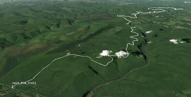
The Tioga West Rim Trail is a hiking trail located in Pennsylvania. Let's visualize it in the 3D Graphics window.
- Right-click on West Rim Trail.kmz in the table of contents.
- Select Zoom To (
 ).
). - Double-click on any part of the trail in the 3D Graphics window to bring up a balloon containing information about the item from the KMZ file.
- When finished, close () the information balloon.

West Rim Trail
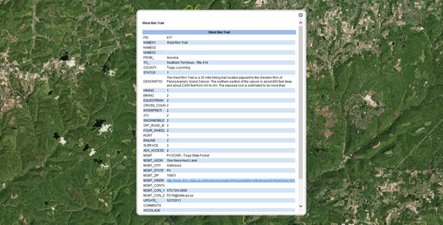
KMZ Information
Using the Get Info Tool
The Get Info Tool allows you to select an area on the 3D globe and get information on any KML items within the selected area.
- Click Get Info Tool (
 ) on the KML toolbar.
 - When the Get Info Tool window appears, click Enable object selection pick in 3D window (
 ).
). - Click and drag a selection box over the West Rim Trail in the 3D Graphics Window.
- In the Get Info Tool, click West Rim Trail to view the properties and values associated with each item.
- Close the window when you have finished exploring the Get Info Tool window.
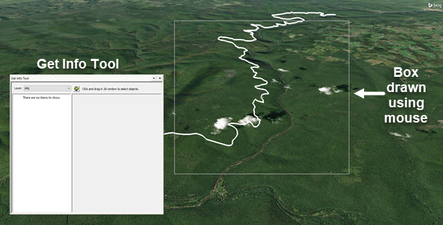
Get Info Tool and Drawn Box
The Get Info Tool window will display information about the KML items within the selected area.
Importing a KMZ file
Import the KMZ into the STK application as an analytical object.
- Expand () West Rim Trail.kmz () in Globe Manager.
- Right-click on West Rim Trail (
 ). Notice the objects that can be imported into the STK application.
 - Select Import as Ground Vehicle.
- Notice in the Object Browser that a new Ground Vehicle (
 ) object named West_Rim_Trail was created.
Visualizing the Ground Vehicle object
Improve the view of the Ground Vehicle (![]() ) object.
) object.
- Right-click on West_Rim_Trail () in the Object Browser.
- Select Zoom To.
- Use your mouse to zoom out until you see the location of West_Rim_Trail and its route.
- Open West_Rim_Trail's () Properties (). Be patient. There are a lot of points.
- On the Basic - Route page, click Set All.
- Select Altitude in the Set All Grid Values window.
- Set the Altitude: value to 3 ft.
- Click to close the Set All Grid Values window.
- Click to accept the changes and close the Properties Browser.

Ground Vehicle Route
Turning on streaming terrain
If you have an Internet connection, turn on Terrain Server for improved situational awareness.
- servers registered through Data Services
- Open STK_Globe_Manager's () Properties ().
- Select the Basic - Terrain page.
- Select the Use terrain server for analysis in check box the Terrain Server section.
- Click to accept the changes and close the Properties Browser.
- Return to the 3D Graphics window.
Ground Vehicle on Terrain
The KML file is still located on the surface of the WGS84 Ellipsoid. The Ground Vehicle (![]() ) route is three (3) feet above the terrain which allows you to see the route better when streaming terrain. This view provides excellent situational awareness of the route and terrain.
) route is three (3) feet above the terrain which allows you to see the route better when streaming terrain. This view provides excellent situational awareness of the route and terrain.
Adding 3D Tiles
Add 3D Tilesets enables you to add or remove 3D Tiles for display in the 3D Graphics window. 3D Tilesets can be used from your hard drive or imported from the Ansys Geospatial Data Cloud. They work best if Terrain Server is on or if you have a local terrain file which has been converted into a PDTT that defines the area where the 3D Tileset is being used. Like a PDTT, 3D Tiles can be used both visually and analytically.
- Select the Hierarchy tab in Globe Manager.
- Select Earth ().
- Click Add Terrain/Imagery () on the Globe Manager toolbar.
- Select Add 3D Tilesets.
- Change the Path: to <Install Dir>\STKData\VO\3DTilesets in the Globe Manager: Add 3D Tilesets window.
- Select AGI_Headquarters.
- Click .
- Right-click on AGI_Headquarters in the Globe Manager.
- Select Zoom To ().
- In the 3D Graphics window, use your mouse to explore the 3D Tileset.

3D Tileset of AGI's Headquarters
Saving your work
Clean up your workspace and save your work.
- Close any open reports, properties and tools.
- Save () your work.
Summary
You began the scenario by opening the Globe Manager. Inside the Globe Manager, you created a Terrain/Imagery set which contained both an image file and a terrain file of Mount St. Helens. Next, you loaded two imagery files of the Organ Pipe Cactus area: one file was a satellite image of the area and the other was a map overlay of the area. The satellite imagery sat on top of the map which wasn't visible in the 3D Graphics window. Using the Render Order tab, you learned how to place one image on top of another. After placing the map on top of the satellite imagery, you were able to adjust the transparency so that you could see both the map and the satellite imagery. You then learned how to import, export, and change the base globe. Next, you inserted a KMZ file into the scenario and imported that file as an analytical object into the STK application. And lastly, you inserted a 3D Tileset in the Globe Manager showing AGI's headquarters in your scenario.
On your own
Earlier in the lesson you loaded the West_Rim_Trail.kmz file into your scenario. Another KMZ file that you will find interesting is the MtStHelens.kmz located in the same folder as the West_Rim_Trail.kmz file.
- Zoom to the St Helens.pdtt.
- Import the Mount St. Helens Worm Flows Route as a Ground Vehicle object.
- The Ground Vehicle appears to float high over the terrain. Go into Mount_Saint_Helens_Worm_Flows_Route (STK Ground Vehicle object) and change all the point altitudes to 3 feet. You will be able to visualize a popular hiking trail located along the volcano.
- There are other KMZ and KML files in the STK software install area that you can look at. If you return to the Globe Manager: Open Terrain and Imagery Data window and set the Path to C:\Program Files\AGI\STK_ODTK 13\STKData\VO\Textures, there are a multitude of files that you can load. Try them out.