STK Premium (Space) or STK Enterprise
You can obtain the necessary licenses for this tutorial by
This lesson requires version 12.7 of the STK software or newer to complete. Optional steps are included if you are using an older version of the STK software.
The results of the tutorial may vary depending on the user settings and data enabled (online operations, terrain server, dynamic Earth data, etc.). It is acceptable to have different results.
Capabilities covered
This lesson covers the following capabilities of the Ansys System Tool Kit® (STK®) digital mission engineering software:
- STK Pro
- Astrogator
- Analysis Workbench
Problem statement
Engineers and operators require a quick way to create initial designs for spacecraft trajectories for mission planning and operations. You want to model an Earth-Moon circular restricted three-body problem (CR3BP) system. The circular restricted three-body problem represents a medium level of model fidelity that simultaneously incorporates the gravitational effects of two massive bodies on some smaller body, like a spacecraft.
Solution
Use the STK/Astrogator® capability and the CR3BP Setup Tool to model an Earth-Moon CR3BP system. The CR3BP Setup Tool is available using STK 12.7 or later. It was built to assist in configuring scenarios to address the CR3BP problem. In this lesson, you will learn how to use the CR3BP Setup Tool to define a new, idealized circular orbit around the Moon and build the necessary components. Before the CR3BP Setup Tool was available, you needed to manually create a custom central body and custom reference frames, and you had to design a force model with customized central bodies. Now, you can do the same thing easily with just a few clicks using the CR3BP Setup Tool.
What you will learn
Upon completion of this tutorial, you will be able to:
- Create a custom central body
- Create unique reference frames
- Design a force model with the customized central bodies and reference frames
Video guidance
Watch the following video. Then follow the steps below, which incorporate the systems and missions you work on (sample inputs provided).
Creating a new scenario
Before you begin with any analysis, you need to create a 30-day scenario.
- Launch the STK application (
 ).
). - Click
 Create a Scenario.
 - Enter the following in the STK: New Scenario Wizard:
- Click when you finish.
- Click Save (
 ) when the scenario loads. A folder with the same name as your scenario is created for you.
 - Verify the scenario name and location shown in the Save As dialog box.
- Click .
| Option | Value |
|---|---|
| Name | EarthMoonCRP |
| Analysis Start Time | 4 Mar 2019 17:00:00.000 UTCG |
| Analysis End Time | + 30 days |
Inserting a satellite
Create a new satellite that you will modify later in the lesson.
- Bring the Insert STK Objects tool (
 ) to the front.
 - Select Satellite (
 ) in the Select An Object To be Inserted list.
 - Select the Insert Default () method.
- Rename Satellite () L1HaloOrbit.
Using the CR3BP Setup Tool
Use the CR3BP Setup Tool, located within the Component Browser's
If you are using a version of the STK software that is older that 12.7 to complete this tutorial, skip to the
Creating a new CR3BP Setup Tool template
Duplicate the installed CR3BP Setup Tool component to create a template for the Noom central body.
- Select the Utilities menu.
- Select Component Browser... (
 ).
). - Select the Design Tools (
 ) folder in the component tree when the Component Browser opens.
 - Select CR3BP Setup Tool (
 ).
). - Click Duplicate component (
 ).
). - Enter Noom Setup in the Name field when the Field Editor opens.
- Click to confirm your selection and to close the Field Editor.
- Select Noom Setup (
 ).
). - Click View properties (
 ).
).
You cannot duplicate components like Noom Setup (![]() ); you can only edit and delete them. This prevents interdependencies as you build and design additional idealized central bodies.
); you can only edit and delete them. This prevents interdependencies as you build and design additional idealized central bodies.
Configuring the Noom central body
In the STK application, a
When creating a new idealized central body in the CR3BP Setup Tool, you can specify the orbit for the central body. For each setup, there is a list of components in the top right with the Mass Parameter and Characteristic components. These values aren't editable, but you can copy them and modify their format. As you create components, they will populate the Associated Objects list.
- Confirm the Central Body is set to Earth.
- Click the ellipsis (
 ) next to the Source Secondary field.
 - Select Moon (
 ) when the Select Component dialog box opens.
 - Click to confirm your selection and to close the Select Component dialog box.
- Leave the Initial Epoch as the scenario start time.
- Select Epoch-centered average source radius in the Ideal Orbit Radius drop-down list.
- Set the Ideal Secondary name to Noom.
- Select the Tab key or click out of the field to validate Ideal Secondary name.
- Click in the Configure Idealized Secondary panel.
- Review the Associated Objects list.
The list of available components will change depending on the selected Central Body.
Valid names for the Ideal Secondary should not have spaces, cannot be the default text in the field, and cannot be "Moon" or the name of another central body.
You have just created a new idealized circular orbit central boy named Noom. You can also verify that it is built by checking the Central Bodies folder (![]() ) in the Component Browser.
) in the Component Browser.
Creating calculation objects for Noom
Along with creating the coordinate system, you will build calculation objects for the new Noom central body.
- Set the Coordinate System to Barycenter-centered if it isn't already set.
- Click .
- Review the Associated Objects list.
- Click for the Calculation Objects for System option.
- Review the Associated Objects list.
- Click .
- Click to close the Component Browser.
You have created new Analysis Workbench Axes, Point, and Systems which depend on Noom.
As you make changes to modify aspects of Noom, yellow dots (![]() ) may appear next to fields to indicate the that listed Associated Objects are inconsistent with a particular Configure Idealized Secondary setting.
) may appear next to fields to indicate the that listed Associated Objects are inconsistent with a particular Configure Idealized Secondary setting.
There are new Cartesian Calculation Objects that depend on the earlier created rotating system. You can also verify that these have been built by checking the Calculation Objects - Cartesian Elems (![]() ) folder in the Component Browser.
) folder in the Component Browser.
After creating the calculation objects for a particular coordinate system, will be unavailable.
Note that Noom has been placed in your User Collection (![]() ).
).
Modeling the Noom central body
Now that you have created Noom, model the Noom central body in the 3D Graphics window.
Creating a new planet object
You can visualize Noom's orbit, but first you need to add a new planet object to the Object Browser.
- Bring the Insert STK Objects tool () to the front.
- Insert a Planet object (
 ) using the Define Properties () method.
 - Set the Central Body to Noom.
- Select Analytic from the Ephemeris Source drop-down list.
- Select the 2D Graphics - Attributes page.
- Make the following changes:
- Increase the Line Width.
- On the 3D Graphics - Attributes page, verify that the Inherit from 2D Planet Graphics check box is selected.
- Click .
| Option | Value |
|---|---|
| Inherit from scenario | Clear |
| Show Subplanet Point | Clear |
| Show Subplanet Label | Clear |
| Show Orbit | Selected |
Modifying your view
View your new secondary body in the 3D Graphics window by pulling the view around to observe its circular orbit.
- Close the 2D Graphics window.
- Right-click on Noom () in the Object Browser.
- Select Zoom To in the shortcut menu.
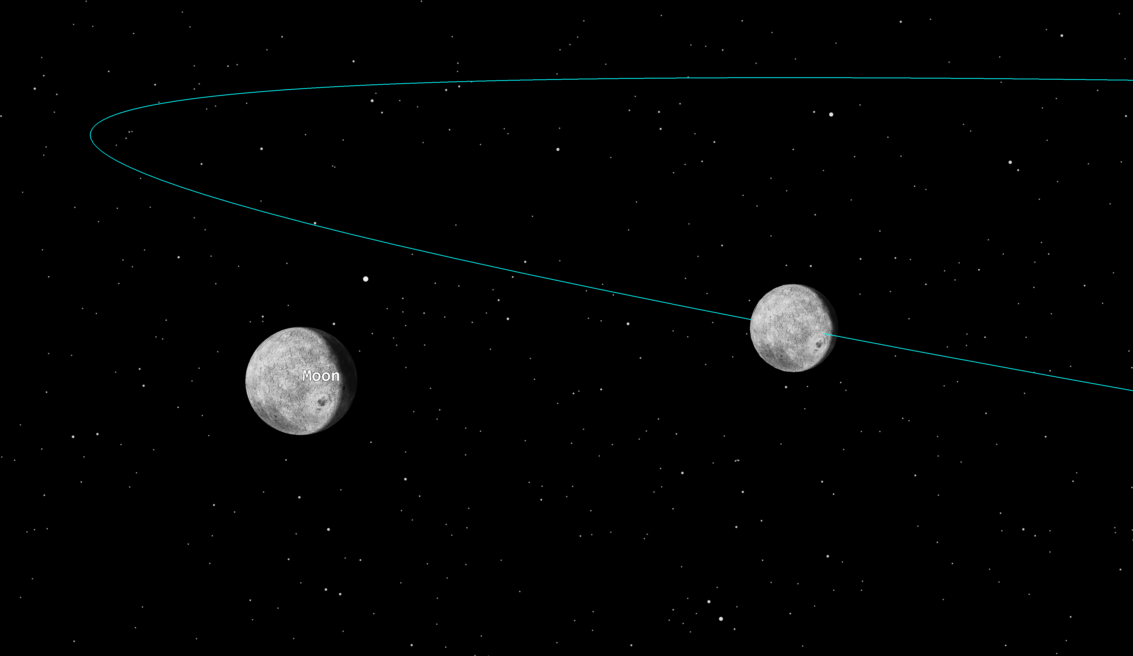
- Move the window around until you see the real Moon and Noom.
- Note Noom’s proximal, but not coincident, position with respect to the Moon.
If you used the "instantaneous" Noom, then both Noom and the Moon would overlap.
Adding Noom as a central body
Add Noom as a new central body using Globe Manager.
- Click the Globe Manager (
 ) icon in the 3D Graphics window toolbar.
 - Click Add Central Body (
 ) in the Globe Manager toolbar.
 - Select Noom in the drop-down menu.
Note that Noom (![]() ) now appears in the Globe Manager hierarchy.
) now appears in the Globe Manager hierarchy.
Opening the Imagery and Terrain Converter to create imagery for Noom
Each central body has a defined ![]() ) Central Body component when you used the Noom Setup (
) Central Body component when you used the Noom Setup (![]() ) CR3BP Setup Tool. While you can overlay a georeferenced image onto Noom to visualize it in the 3D Graphics window, but you must first
) CR3BP Setup Tool. While you can overlay a georeferenced image onto Noom to visualize it in the 3D Graphics window, but you must first
- Select the Utilities menu in the Menu bar.
- Select Imagery and Terrain Converter....
Using the Single Image Converter
The Single Image Converter creates STK-compatible image files from source images and terrain data. Terrain and image files, like the default georeferenced textures used with the STK software's installed central bodies, cannot be reprojected from one central body onto another central body. To put it another way, you cannot take the default texture image for the Moon, which contains embedded geospatial content for the Moon ellipsoid, and use it on Noom directly; you must fist use the Single Image Converter to map the texture file to the Noom central body's shape.
- Ensure the Single Image page is selected.
- Select the ellipsis () next to the Image Filename field in the Input Data panel.
- Navigate to <Install Dir>\STKData\VO\Textures when the File dialog box opens.
- Select Moon.jp2.
- Click to confirm your selection and to close the File dialog box.
- Select AGI Image (pdttx) in the Format drop-down list in the Image File Panel of the Output Data panel.
- Select Noom in the Central Body drop-down list in the Input Data panel.
- Set the Filename in the Output Data Image File to Noom.pdttx.
- Click .
- Click to close the Imagery and Terrain Converter.
Moon.jp2 is georeferenced JPEG 2000 (JP2) image file associated with the Moon central body.
Note that the Central Body field has been updated to Moon, and is read-only.
You must select AGI Image (pdttx) before you can change the central body.
This will associate the image with the Noom central body.
Updating Noom's imagery in Globe Manager
Add the converted image to the your custom Noom central body to display in the 3D Graphics window.
- Right-click on Noom (
 ) in the Globe Manager hierarchy.
 - Select Add Terrain/Imagery... (
 ) in the shortcut menu.
 - Select the check box for Noom.pdttx when the Globe Manager: Open Terrain and Imagery Data dialog box.
- Click to add the central body texture to Noom and to close the Globe Manager: Open Terrain and Imagery Data dialog box.
- Expand (
 ) Noom () in the Globe Manager hierarchy.
 - Note that Noom.pdttx (
 ) has been added to Noom.
 - Note also that the other central bodies () in the Globe Manager Hierarchy are associated with their corresponding georeferenced JP2 files.
- Clear the Moon () check box in the Globe Manager Hierarchy tab.
- Save () your scenario.
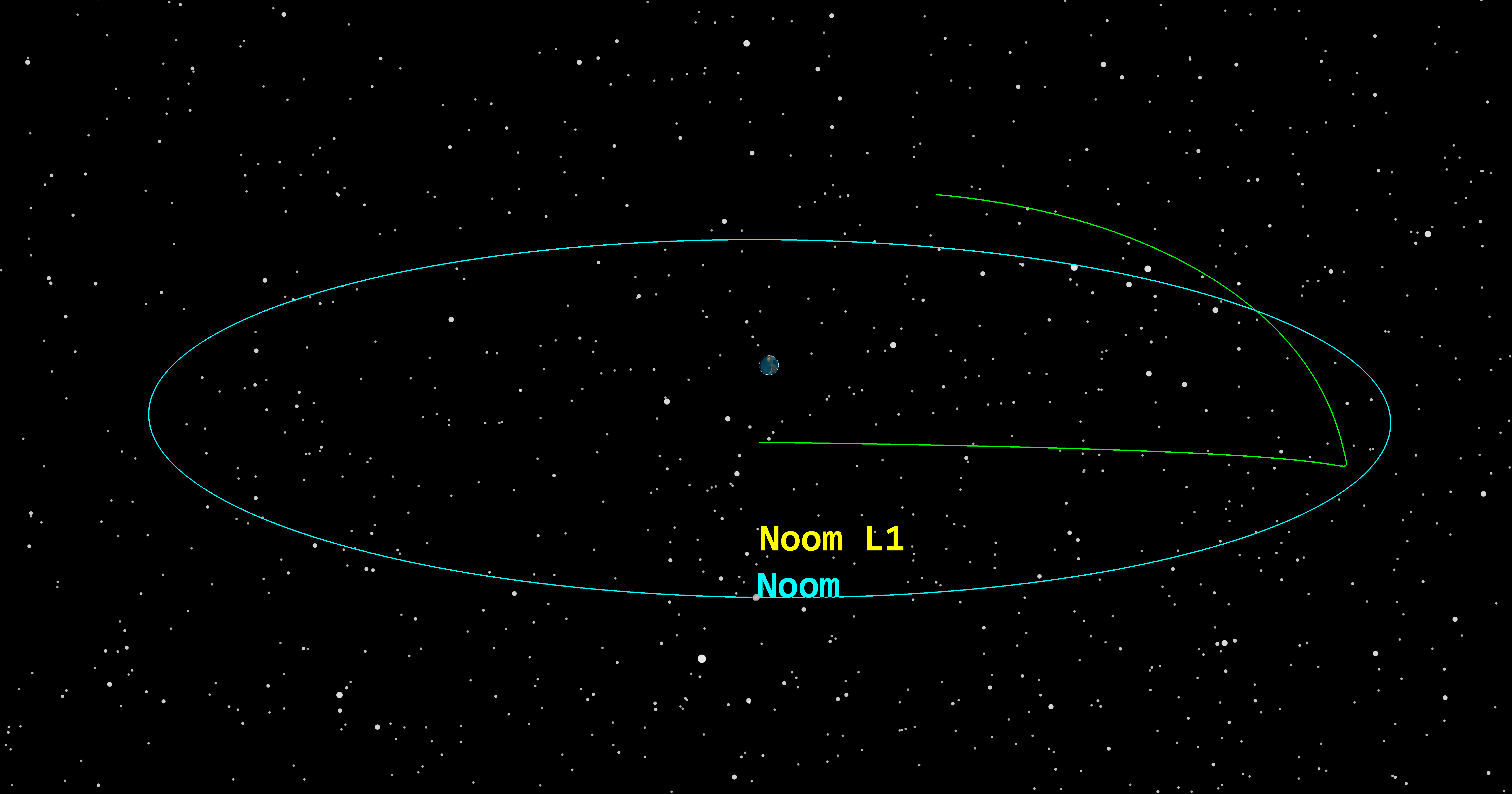
Your 3D window should look similar to this:
The MooN and Noom in orbit
You may think to yourself, "Well that was easy, but what did I actually do?" You need to break it down. The next sections help you walk though manually building each component for a new object called Luna. This helps you to understand the various dependencies.
Creating a central body Luna with manual configuration
If you did not have the CR3BP Setup Tool, which was introduced in version 12.7 of the STK software, then you would need to build the
- Select the Utilities menu.
- Select Component Browser... ().
- Select Central Bodies () in the component tree.
- Select AsteroidTemplate ().
- Click Duplicate component ().
- Enter Luna Setup in the Name field, to differentiate it from Noom Setup ().
- Enter Circular Orbit Moon in the User Comment field.
- Click .
Configuring Luna's properties
- Double-click on Luna Setup () to open its properties.
- Set the following properties when the CentralBody - Luna dialog box opens:
- Click beside the Analytic field in the Gravity Models panel.
- Set the following Gravity Model Parameters when the Gravity Model dialog box opens:
- Ensure J2, J3, and J4 in the Zonals panel are set to zero (0).
- Click to confirm your changes and to close the Gravity Model dialog box.
- Ensure Sphere is selected as the Shape option in the Shape panel.
- Set the Radius in the Shape panel to 1737.4 km.
| Option | Value |
|---|---|
| Gravitational Parameter | 4902.800305555400 km^3/sec^2 |
| Parent | Earth |
| Gravity Models | ZonalsToJ4 |
| Option | Value |
|---|---|
| Gravitational Parameter | 4902.800305555400 km^3/sec^2 |
| Ref. Distance | 1737.4 km |
Defining the attitude
Use the IAU_1994 attitude definition in your analysis.
- Click the ellipsis () next to the Attitude field.
- Ensure IAU 1994 () is selected in the Available Components list.
- Set the following options in the Component Details list when the VaMultiCS for STK dialog box opens:
- Click to confirm your changes and to close the VaMultiCS for STK dialog box.
| Option | Value |
|---|---|
| Epoch | 2458547.209134070 |
| RA | 0 deg |
| Dec | 90 deg |
| dRA/dt | 0 deg/sec |
| dDec/dt | 0 deg/sec |
| Offset | 180 deg |
| Rate | 1.480234944229988e-04 deg/sec |
Defining the analytic orbit for the ephemeris
Take a moment to define the Analytic Orbit for the Ephemeris of Luna.
- Click in the Ephemeris panel.
- Set the Epoch (JED) to 2458547.209134070 when the Ephemeris dialog box opens.
- Set the following options:
- Click to close the Ephemeris dialog box.
- Click to close the CentralBody - Luna dialog box.
- Click to close the Component Browser.
| Option | Value | Rate |
|---|---|---|
| Semi-major Axis | 385424.900010217330418527 km | 0 km/sec |
| Eccentricity | 0 | 0 |
| Inclination | 21.681031236043310 deg | 0 deg/sec |
| Right ascension of ascending node | 12.619041698874328 deg | 0 deg/sec |
| Longitude of Periapsis | 140.441905041691513 deg | 0 deg/sec |
| Mean longitude | 323.316086420511397 deg | 0.000151175657974 deg/sec |
Modeling the Luna central body
Now that you created Luna, display the new central body in the scenario.
Creating a new Planet object
You can visualize Luna's orbit, but first you need to add a new Planet object to the Object Browser.
- Bring the Insert STK Objects tool () to the front.
- Insert a Planet object () using the Define Properties () method.
- Set the Central Body to Luna.
- Set the Ephemeris Source to Analytic.
- Select the 2D Graphics - Attributes page.
- Make the following changes:
- Increase the Line Width.
- On the 3D Graphics - Attributes page, ensure that the Inherit from 2D Planet Graphics check box is selected.
- Click .
| Option | Value |
|---|---|
| Inherit from scenario | Clear |
| Show Subplanet Point | Clear |
| Show Subplanet Label | Clear |
| Show Orbit | Selected |
Modifying your view
View your new secondary body in the 3D Graphics window by pulling the view around to observe its circular orbit. Note the real Moon.
- Close the 2D Graphics Window.
- Right-click on Luna () in the Object Browser.
- Select Zoom To in the shortcut menu.
- Note Luna’s proximal, but not coincident, position with respect to the Moon.
Adding Luna as a central body
Add Luna as a new Central Body using Globe Manager.
- Click the Globe Manager () icon in the 3D Graphics window toolbar.
- Click Add Central Body () in the Globe Manager toolbar.
- Select Luna in the drop-down menu.
Note that Luna (![]() ) now appears in the Globe Manager hierarchy.
) now appears in the Globe Manager hierarchy.
Opening the Imagery and Terrain Converter
Use the Imagery and Terrain Converter to create an image file from a that is compatible for display with the Luna central body in the 3D Graphics window.
- Select the Utilities menu in the Menu bar.
- Select Imagery and Terrain Converter....
Using the Single Image Converter
Use the Imagery and Terrain Converter to convert the Moon central body's default texture file and map it to Luna's central body shape.
- Ensure the Single Image page is selected.
- Select the ellipsis () next to the Image Filename field in the Input Data panel.
- Navigate to <Install Dir>\STKData\VO\Textures when the File dialog box opens.
- Select Moon.jp2.
- Click to confirm your selection and to close the File dialog box.
- Select AGI Image (pdttx) in the Format drop-down list in the Image File Panel of the Output Data panel.
- Select Luna in the Central Body drop-down list in the Input Data panel.
- Set the Filename in the Output Data Image File to Luna.pdttx.
- Click .
- Click to close the Imagery and Terrain Converter.
Updating Luna's imagery in Globe Manager
Add the converted image to the your custom Luna central body to display in the 3D Graphics window.
- Right-click on Luna () in the Globe Manager hierarchy.
- Select Add Terrain/Imagery... () in the shortcut menu.
- Select the check box for Luna.pdttx.
- Click to add the central body texture to Luna and to close the Globe Manager: Open Terrain and Imagery Data dialog box.
- Clear the Moon () check box in the Globe Manager Hierarchy tab.
- Save () your scenario.
Configuring the coordinate systems
Create custom components in the Analysis Workbench capability to define the Barycenter reference frame and system associated with the system comprised of the new central body (Luna) and the Earth.
Selecting the central body for the vector components
Open Analysis Workbench and select Earth as the central body.
- Open Analysis Workbench from the Analysis menu or by clicking the toolbar icon (
 ).
). - Select the Vector Geometry tab.
- Select Primary Central Bodies in the Filter by drop-down list.
- Select Earth ().
You will create all of your components under Earth.
Creating a new displacement vector
Create a new displacement vector between the center points of Earth and Luna.
- Click Create new Vector (
 ).
). - Leave the Type as Displacement when the Add Geometry Component dialog box opens.
- Name the vector EarthLunaVector.
- Ensure the Origin Point is set to Earth Center.
- Click the ellipsis () next to the Destination Point field.
- Select Luna () under Installed Components in the object tree when the Select Reference Point dialog box opens.
- Select Center (
 ) in the Points for: Luna list.
 - Click .to confirm your selection and to close the Select Reference Point dialog box.
- Clear the Apparent check box.
- Click to confirm your changes and to close the Add Geometry Component dialog box.
You care about the true location of your central bodies regardless of any light time delays.
Creating the Earth-Luna axes
Create a new axes component for Earth and Luna.
- Click Create new Axes (
 ) .
) . - Click next to the Type field.
- Select Aligned and Constrained () in the Select Component Type list when the Select Component Type dialog box opens.
- Click to confirm your selection and to close the Select Component Type dialog box.
- Name the axes EarthLunaAxes.
Specifying the aligned vector parameters
Specify the parameters for the aligned vector.
- Click the ellipsis () next to the Aligned Vector field in the Aligned panel.
- Select EarthLunaVector () under My Components () in the Vectors for: Earth list when the Select Reference Vector dialog box opens.
- Click to confirm your selection and to close the Select Reference Vector dialog box.
- Set the Cartesian values in the Aligned frame to:
| Option | Value |
|---|---|
| X | 1 |
| Y | 0 |
| Z | 0 |
The EarthLunaVector will provide the X unit vector for the axes.
Specifying the constrained vector parameters
Specify the parameters for the constrained vector.
- Click the ellipsis () next to the Constrained Vector field in the Aligned panel.
- Select Luna () in the Object List.
- Select Orbit_AngMomementum () under Installed Components () in the Vectors for: Luna list.
- Click .
- Set the Cartesian components to:
- Click .
- Save () your scenario.
| Option | Value |
|---|---|
| X | 0 |
| Y | 0 |
| Z | 1 |
The angular momentum vector for Luna’s orbit will provide the Z unit vector for the axes, and the Y unit vector will result as a consequence of the right-hand rule.
Creating the EarthLunaPrimaryCentered system
Create a new system centered around Earth.
- Click Create new System (
 ).
). - Leave the Type as Assembled.
- Name the system EarthLunaPrimaryCentered.
- Leave the Origin Point as Earth Center.
- Click the ellipsis () next to the Reference Axes field.
- Select EartLunaAxes () under My Components () in the Axes for: Earth list when the Select Reference Axes dialog box opens.
- Click to confirm your selection and to close the Select Reference Axes dialog box.
- Click .
Creating a barycentered frame
Now, create a barycentered frame, a common frame when working with the CR3BP.
- Click Create new Point (
 ).
). - Leave the Type as Fixed in System.
- Name the point EarthLunaBarycenter.
- Leave the Fixed Point Type as Cartesian.
- Set the X component to 4683.13788266 km.
- Click the ellipsis () next to the Reference System field.
- Set the Reference System field to Earth EarthLunaPrimaryCentered.
- Select EarthLunaPrimaryCentered () under My Components () in the Systems for: Earth list when the Select Reference System dialog box opens.
- Click to confirm your selection and to close the Select Reference System dialog box.
- Click .
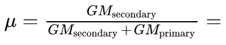
Use the CR3BP mass parameter to define the point. It is μ nondimensional units from the Earth center along the Earth-Luna direction. The mass parameter, μ, is given as:
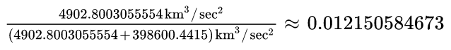
Note the two-body mass parameter units cancel, leaving a nondimensional three-body mass parameter. Multiplying the three-body mass parameter by the characteristic distance of the system, which is the constant semimajor axis of the secondary’s circular orbit, gives:

Creating the EarthLunaBarycentered system
You now have all of the components to create the barycentered coordinate system.
- Click the Create new System () button again.
- Leave the Type as Assembled.
- Name the system EarthLunaBarycentered.
- Set the Origin Point to EarthLunaBarycenter.
- Set the Reference Axes to EarthLunaAxes.
- Click .
- Click to close Analysis Workbench.
- Save () your scenario.
You created five new components in Analysis Workbench under the Earth central body:
- EarthLunaVector ()
- EarthLunaAxes ()
- EarthLunaBarycenter ()
- EarthLunaBarycentered ()
- EarthLunaPrimaryCentered ()
Configuring calculation objects
Create some custom components so that you can report them out after the study.
- Select the Utilities menu.
- Select Component Browser... ().
- Expand () the Calculation Objects () folder.
- Select Cartesian Elems ().
- Duplicate () each of the six position and velocity calculation objects.
- Name the duplicates in the following way, with EL standing for Earth-Luna:
- Open each of the six duplicated elements (
 ) and change the CoordSystem to Earth EarthLunaBarycentered.
 - Click to close the Component Browser.
- Save () your scenario.
| Original | Duplicate Name |
|---|---|
| Vx | ELVx |
| Vy | ELVy |
| Vz | ELVz |
| X | ELRx |
| Y | ELRy |
| Z | ELRz |
Continuing the Analysis
The rest of this lessons uses the components for Noom built with the CR3BP Setup Tool. If you did not build Noom with the CR3BP Setup Tool, and instead manually built out Luna, use Luna and its respective components in place of Noom.
Adding a second 3D view
You can open multiple 3D views that enable you to view important reference frames for your systems.
Duplicating your existing 3D Graphics window
Use the settings for the existing 3D Graphics window and update them to display your rotating frame trajectory.
- Select the View menu.
- Select Duplicate 3D Graphics Window.
- Select 3D Graphics 1 - Earth in the Duplicate 3D Graphics Window submenu.
Updating the duplicate 3D Graphics window's properties
You may want to add axes, planes, or additional libration points to the 3D Graphics windows. For now, just add the Earth-Noom L1 libration point.
- Click Properties () in the new 3D Graphics window.
- Select the Vector page when the 3D Graphics properties window opens.
- Select the Points tab.
- Click .
- Select Noom () in the Object List.
- Select the L1 (
 ) point under Installed Components () in the Components for: Noom list. You will need to scroll down to the bottom of the list.
 - Click .
- Change the size of the point to your preference.
- Optionally, change the color of the point.
You can add the L1 point to the other 3D Graphics window by following the steps in this section.
Updating the reference system
Update the duplicate 3D Graphics window's reference system to reference the Earth-Noom barycenter.
- Click the ellipsis () next to the System field.
- Change the System field to EarthNoomBarycenterCenteredRotating (
 ).
). - Click .
- Click to save your changes and to close the 3D Graphics window properties window.
If you are using Luna as your central body, select EarthLunaBarycentered (![]() ) for all equivalent changes.
) for all equivalent changes.
Configuring the force model
You built and defined the Noom central body. Now, create a force model that utilizes it.
Creating a custom Three-Body component
Use the component browser to create a new Three-Body propagator.
- Select the Utilities menu.
- Select Component Browser... ().
- Select the Propagators () folder.
- Select Three Body ().
- Click Duplicate component ().
- Rename the new propagator EarthNoomCRP.
Updating the force model's secondary body
Update the secondary body to reference Noom.
- Double-click on EarthNoomCRP ().
- Click the ellipsis () next to the Secondary Body field when the Propagator - EarthNoomCRP dialog box opens.
- Set the secondary body to Noom () when the Select Component dialog box opens.
- Click to confirm your selection and to close the Select Component dialog box
- Click to confirm your changes and to close the Propagator - EarthNoomCRP dialog box.
- Click to close the Component Browser.
Setting up the Astrogator satellite
You added the L1HaloOrbit (![]() ) Satellite object at the beginning of this tutorial. Now that you have defined all the components of your new system, place the satellite in orbit about the L1 point.
) Satellite object at the beginning of this tutorial. Now that you have defined all the components of your new system, place the satellite in orbit about the L1 point.
Configuring the 3D view
Go through L1HaloOrbit's (![]() ) properties and set its specific parameters.
) properties and set its specific parameters.
- Double-click L1HaloOrbit () to open its properties.
- Select the 3D Graphics - Orbit System page.
- Click .
- Change the Filter by option to Primary Central Bodies.
- Select Noom () in the object tree.
- Select EarthNoomBarycenterCenteredRotating (
 ) under Installed Components () from the Systems for: Noom list.
 - Click .
Updating the orbit system displays in the 3D Graphics windows
Update L1HaloOrbit (![]() )'s orbit systems to display differently in the two 3D Graphics windows.
)'s orbit systems to display differently in the two 3D Graphics windows.
- Return to the 3D Graphics - Orbit System page for L1HaloOrbit ().
- Ensure EarthNoomBarycenterCenteredRotating is selected. If EarthNoomBarycenterCenteredRotating is not highlighted, click it once to highlight it.
- Select 3D Graphics 2 - Earth in the 3D Windows panel.
- Select Inertial by Window to highlight it.
- Select 3D Graphics 1 - Earth in the 3D Windows panel.
- Click .
- Save () your scenario.
Configuring the orbit
You created a satellite object very early in your scenario. Now, modify this satellite’s orbit to place it in orbit about the Earth Noom L1 position by specifying its initial state.
- Select the Basic - Orbit page.
- Change the Propagator to Astrogator.
- Ensure the Initial State (
 ) segment is selected in the Mission Control Sequence (MCS).
 - Ensure the Elements tab is selected.
- Enter the following properties:
| Option | Value |
|---|---|
| Coord. System | Noom EarthNoomBarycenterCenteredRotating |
| Coordinate Type | Cartesian |
| X Component | 322022.503957876 km |
| Y Component | 0 km |
| Z Component | 54884.505761407 km |
| Vx Component | 0 km/sec |
| Vy Component | 0.2585583925805190 km/sec |
| Vz Component | 0 km/sec |
Updating the propagator
Update the Propagate (![]() ) segment to use the EarthNoomCRP propagator.
) segment to use the EarthNoomCRP propagator.
- Select the Propagate (
 ) segment in the MCS.
 - Click the ellipsis () next to the Propagator field.
- Select EarthNoomCRP () when the Select Component dialog box opens.
- Click to confirm your selection and to close the Select Component dialog box.
- Click .
- Set the Minimum propagation time to 10 sec when the Propagator Advanced dialog box opens.
- Click to confirm your change and to close the Propagator Advanced dialog box.
Updating the stopping condition
Add a new Z-X Plane Cross stopping condition.
- Click New... (
 ) in the Stopping Conditions panel.
 - Select Z-X Plane Cross () when the New Stopping Condition dialog box opens.
- Set the following options:
- Click to confirm your changes and to close the New Stopping Condition dialog box.
- Remove or clear the Duration stopping condition.
| Option | Value |
|---|---|
| Criterion | Cross Increasing |
| Repeat Count | 5 |
| Coord. System | Noom EarthNoomBarycenterCenteredRotating |
Updating the results
Update the propagate segment to use the Barycenter components.
- Right-click on the Propagate () segment.
- Select Results... in the shortcut menu.
- Expand () the Cartesian Elems () folder when the User-Selected Results - Propagate dialog box opens.
- Insert (
 ) the six BarycenterEarthNoom () position and velocity calculation components.
 - Click to confirm your selection and to close the User-Selected Results - Propagate dialog box.
- Save () your scenario.
Generating the results
Since you defined your system and your satellite, you can run your MCS to visualize your solution and generate various data.
- Run the MCS. Assuming everything has gone according to plan, you should see an Earth-Noom L1 halo orbit in the rotating frame
- Right-click on the Propagate segment.
- Select Summary... in the shortcut menu.
- Scroll to the bottom of the Astrogator MCS Propagate Summary and note the User-selected results. These should include the six Earth-Noom position and velocity calculation objects. The values should be close to what you used for the initial conditions.
- Close the Astrogator MCS Propagate Summary report.
- Save () your scenario.
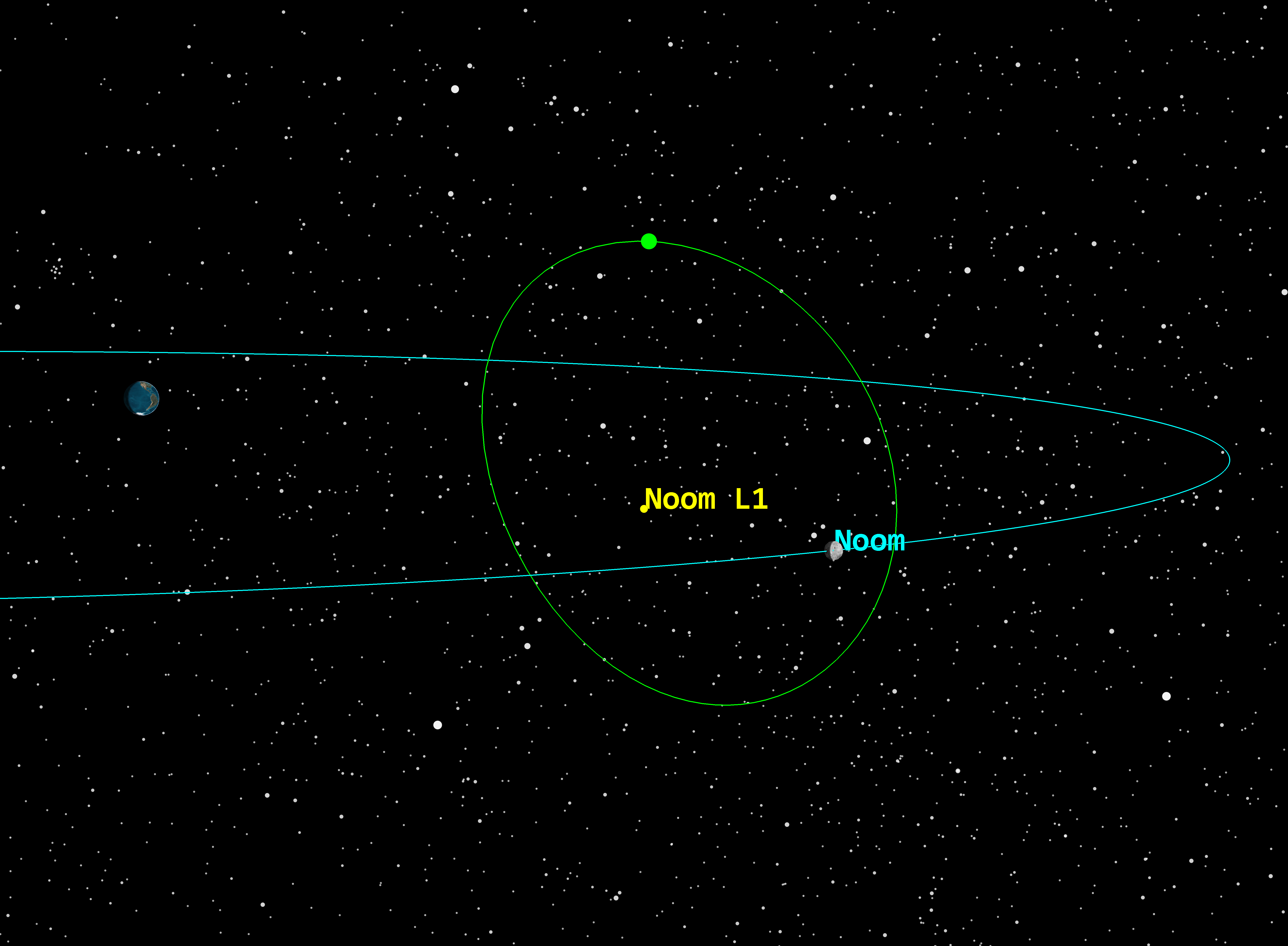
Earth-Noom L1 halo orbit, rotating view
Earth-Noom L1 halo orbit, inertial view
Building a Jacobi integral report
You can generate a final relevant report for the three-body analysis to validate your work.
Creating a custom report style
Create a new custom report style in the Report & Graph Manager to begin designing your report.
- Right-click on L1HaloOrbit () in the Object Browser.
- Select Report & Graph Manager (
 ) in the shortcut menu.
 - Select the MyStyles () folder.
- Click Create new report style (
 ).
). - Name your new report Jacobi Integral Report.
- Select the Enter key.
Configuring the data providers
Insert the data providers needed to build your Jacobi integral report.
- Expand () the Astrogator Values () data provider.
- Expand () the MultiBody() data provider group.
- Insert () the Time (
 ) data provider element to the Report Contents list.
 - Insert () Jacobi_Integral () data provider element to the Report Contents list.
- Click .
- Click .
Notice the Jacobi Integral over the length of the propagation. A value that is constant to several digits indicates that the model is numerically simulated properly.
Building an L1 halo orbit for a new system
The halo orbit you built used predefined values. But how would you create a halo orbit for a new system? How should you approach a new solution? In your case, you have an existing solution, so use that to build additional halo orbits.
Look at the dimensional units. For an Earth-Moon use case, the CR3BP mass parameter, μ, is given as:
Note the two-body mass parameter units cancel, leaving a nondimensional three-body mass parameter. This is a good start, but you need a few other parameters. You can calculate these, or you can find them from the CR3BP Setup Tool.
Creating a new CR3BP design
- Select Component Browser... () in the Utilities menu.
- Select the Design Tools () folder.
- Duplicate () the CR3BP Setup Tool ().
- Set the name to BlueMoon Setup.
- Set Moon as the Source Secondary.
- Set the Ideal Orbit Radius as Instantaneous characteristic distance.
- Name the Ideal Secondary BlueMoon.
- Create the new Associated Objects, as in the Modeling the new central body Noom section.
Determining Bluemoon's characteristic values
You need to find your characteristic values, and you need to be precise.
- Click the units selector(
 ) for each of the parameters listed below (Mass Parameter to Characteristic Acceleration). They will appear grayed out, but you can edit them.
 - Click Format in the shortcut menu and to open the Format Dialog box.
- It is best practice (but not required) to change the precision to 16 and the notation to Floating point. Optionally, you can also change the units, in this case, to m/sec from km/sec.
- Click to accept your changes and to close the Format Dialog box.
- Copy the values. For completeness, here are the parameters for BlueMoon.
- You can reuse two components, L and V, from Noom to solve for BlueMoon's L1 halo. Repeat the steps above to find the precise values for Noom's L and V. Call these Lnoom and Vnoom. The mass parameter, μ, for BlueMoon and Noom are the same.
- Noom's Characteristic Distance (Lnoom) = 385424.9000102173304185 km
- Noom's Characteristic Velocity (Vnoom) = 1.0231837400529219622 km/sec
- From your previously solved orbit of L1HaloOrbit, complete the following actions:
- Take the old X and Z values from Noom's initial state segment and divide by Lnoom.
- Take the old Vy value from the Noom's initial state segment and divide by Vnoom.
- Once you have the nondimensional state (X, Y, Z, Vx, Vy, Vz), redimensionalize it with the characteristic distance and velocity from the tool. To redimensionalize your state vector, multiply the appropriate nondimensionalized components (position and velocity) by the characteristic distance and velocity you get from the system you have set up with the design tool. See the simplified expressions below:
- X' = L' * (Xnoom/Lnoom) = 339522.4354 km
- Z' = L' * (Znoom/Lnoom) = 57867.13919907630 km
- V'y = V' * (Vynoom/Vnoom) = 0.2518068232865140 km/sec
| Parameter | Value |
|---|---|
| Mass Parameter | 0.0121505846734139 |
| Characteristic Distance (L) (Call it L' for BlueMoon) | 406370.3595444307429716 km |
| Characteristic Time (T = √ ( L^3 / (GM_Earth + GM_Moon))) | 407811.5490727517171763 sec |
| Characteristic Velocity (V = L/T) (Call it V' for BlueMoon) | 0.996466 km/sec |
| Characteristic Acceleration | 0.0024434473292663 m/sec^2 |
This process should work because the three-body μ values should be the same in this tutorial; only the characteristic quantities should be different.
Modeling the BlueMoon system
Now that you have determined your characteristic values, continue building out BlueMoon.
- Repeat the steps used for Noom to create a new Planet () object for BlueMoon, visualize it, and create a force model for it.
- Model and display your satellite with your newly created coordinate systems, propagators, and newly solved X', Z', and V'y. You will also add a new VGT system for visualization.
Saving your work
Clean up and close out your scenario.
- Close any open reports, properties, and the Report & Graph Manager.
- Save () your work.
Summary
In this lesson, you set up a scenario to address the circular restricted three-body problem. You utilized the Design Tool CR3BP Setup Tool to build the components, but also investigated how you could build components manually. Then you designed a new force model and used that to model a satellite in L1 halo orbit of your idealized Moon, Noom. Finally, you examined some reports and reviewed how to model other L1 halo orbits using the solution derived in this work.