Triangle Mesh Primitive |
Triangles are used in real-time computer graphics because they are planar and can be rasterized very quickly in hardware. Several triangles form a mesh. Meshes are used to represent just about anything in a 3D scene. For example, the globe is represented using meshes.
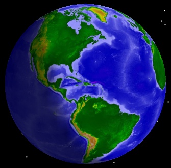 The globe. | 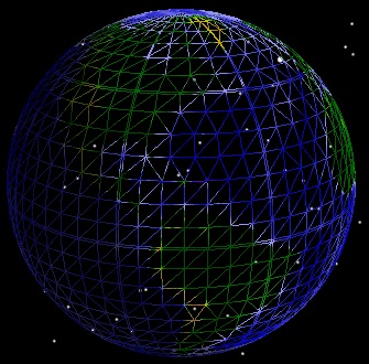 Triangle meshes that represent the globe. |
TriangleMeshPrimitive is used to render arbitrary triangle meshes. This includes polygons on the globe (e.g. states or countries), terrain and imagery extents, ellipses, and walls. The triangle mesh is a generic rendering object that takes input from other objects that compute triangles. For example, the surface polygon triangulator takes boundary positions on the globe as input and outputs triangles that represent the filled interior region. These triangles are then used as input to the triangle mesh.
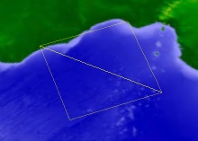
SurfaceExtentTriangulator computes triangles for a rectangular extent on the surface or at a constant altitude. The example code below uses the extent triangulator and the triangle mesh primitive to render the extent around Louisiana:
EarthCentralBody earth = CentralBodiesFacet.GetFromContext().Earth;
CartographicExtent extent =
new CartographicExtent(Trig.DegreesToRadians(-94.0), // West
Trig.DegreesToRadians(29.0), // South
Trig.DegreesToRadians(-89.0), // East
Trig.DegreesToRadians(33.0)); // North
SurfaceTriangulatorResult triangles = SurfaceExtentTriangulator.Compute(earth, extent);
TriangleMeshPrimitive mesh = new TriangleMeshPrimitive(SetHint.Infrequent);
mesh.Set(triangles);
mesh.Color = Color.White;
SceneManager.Primitives.Add(mesh);
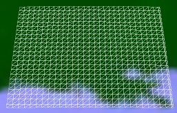
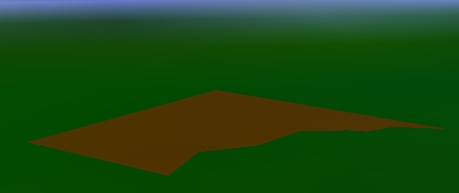
SceneManager.Render();The image on the left shows the output of the extent triangulator, and the image on the right shows the actual results of executing the example.
 Triangles from Extent Triangulator |  Rendered using Triangle Mesh |
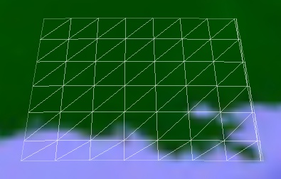
To see the triangles that make up a mesh, set the triangle mesh's Wireframe property to true. |
To create an extent at altitude, use the Compute method which takes an altitude parameter:
SurfaceTriangulatorResult triangles =
    SurfaceExtentTriangulator.Compute(earth, extent,
                                      75000.0, // Altitude in meters
                                      Trig.DegreesToRadians(1.0));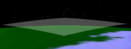
In addition to an altitude, this method also takes a granularity that defines how many triangles should be used when computing the mesh. A mesh with more triangles will conform to the surface better but consume more memory and render slower. The default granularity is 1 degree. The following images demonstrate the effects of changing the granularity.
 Granularity: 0.25 degrees. Triangles: 1,334. | 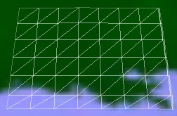 Granularity: 1 degree. Triangles: 96. | 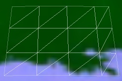 Granularity: 2 degrees. Triangles: 24. |
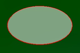
SurfacePolygonTriangulator computes triangles for a polygon on the surface or at a constant altitude. This is commonly used for country and state borders, sensor footprints, and ground ellipses. The polygon triangulator works similarly to the extent triangulator except its input is a set of points on the surface that define a boundary to compute a mesh for, rather than a rectangular extent.
The following example passes the boundary positions for Washington D.C. to the polygon triangulator, which is then used as input to the triangle mesh:
List<Cartographic> positions = new List<Cartographic>
{
    new Cartographic(Trig.DegreesToRadians(-77.008232), Trig.DegreesToRadians(38.9665570), 0),
    new Cartographic(Trig.DegreesToRadians(-76.911209), Trig.DegreesToRadians(38.8899880), 0),
    new Cartographic(Trig.DegreesToRadians(-77.045448), Trig.DegreesToRadians(38.7881200), 0),
    new Cartographic(Trig.DegreesToRadians(-77.035248), Trig.DegreesToRadians(38.8139150), 0),
    new Cartographic(Trig.DegreesToRadians(-77.045189), Trig.DegreesToRadians(38.8293650), 0),
    new Cartographic(Trig.DegreesToRadians(-77.040405), Trig.DegreesToRadians(38.838413), 0),
    new Cartographic(Trig.DegreesToRadians(-77.039078), Trig.DegreesToRadians(38.862431), 0),
    new Cartographic(Trig.DegreesToRadians(-77.067886), Trig.DegreesToRadians(38.886101), 0),
    new Cartographic(Trig.DegreesToRadians(-77.078949), Trig.DegreesToRadians(38.915600), 0),
    new Cartographic(Trig.DegreesToRadians(-77.122627), Trig.DegreesToRadians(38.932060), 0),
    new Cartographic(Trig.DegreesToRadians(-77.042389), Trig.DegreesToRadians(38.993431), 0),
    new Cartographic(Trig.DegreesToRadians(-77.008232), Trig.DegreesToRadians(38.966557), 0),
};

EarthCentralBody earth = CentralBodiesFacet.GetFromContext().Earth;
SurfaceTriangulatorResult triangles = SurfacePolygonTriangulator.ComputeCartographic(earth, positions);

TriangleMeshPrimitive mesh = new TriangleMeshPrimitive(SetHint.Infrequent);
mesh.Set(triangles);
mesh.Color = Color.Red;
SceneManager.Primitives.Add(mesh);
The polygon triangulator is efficient and supports dynamic polygons, which are commonly used for sensor footprints. At each time step, the triangulation can be recomputed with new boundary positions, then used as input to the triangle mesh's Set method.
Technical Details: The polygon triangulator uses an ear clipping algorithm, with optimizations described in our blog post: Triangulation Rhymes With Strangulation. |
Similar to the extent triangulator, the polygon triangulator provides methods to create the mesh at an altitude or with a custom granularity.
The polygon triangulator can triangulate polygons with an interior hole, like the one shown below, when a list of points defining the hole is used as input.
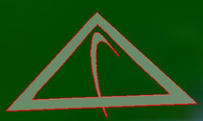
The winding order of a hole does not have to be the same as the winding order of the boundary. The following example triangulates a polygon with a hole, and creates a triangle mesh primitive for the interior fill and two polyline primitives that outline the mesh.
SurfaceTriangulatorResult triangles = SurfacePolygonTriangulator.Compute(earth, positions, holePositions);

TriangleMeshPrimitive mesh = new TriangleMeshPrimitive();
mesh.Set(triangles);
mesh.Color = Color.Gray;
mesh.Translucency = 0.5f;
SceneManager.Primitives.Add(mesh);

PolylinePrimitive boundaryLine = new PolylinePrimitive();
boundaryLine.Set(triangles.BoundaryPositions);
boundaryLine.Color = Color.Red;
boundaryLine.Width = 2.0f;
SceneManager.Primitives.Add(boundaryLine);

PolylinePrimitive holeLine = new PolylinePrimitive();
holeLine.Set(holePositions);
holeLine.Color = Color.Red;
holeLine.Width = 2.0f;
SceneManager.Primitives.Add(holeLine);
ExtrudedPolylineTriangulator computes triangles for extrusions perpendicular to the surface. The extrusion is defined by boundary positions, similar to the input to the surface polygon triangulator. In addition, the altitude for both the bottom and top of the extrusion are specified. The bottom of the extrusion is not required to be on the ground, as the following example demonstrates:
ExtrudedPolylineTriangulatorResult triangles =
    ExtrudedPolylineTriangulator.ComputeCartographic(earth, positions,
                                                     10000, 25000, WindingOrder.CounterClockwise);

TriangleMeshPrimitive mesh = new TriangleMeshPrimitive(SetHint.Infrequent);
mesh.Set(triangles);
mesh.Color = Color.Blue;
mesh.Translucency = 0.4f;

SceneManager.Primitives.Add(mesh);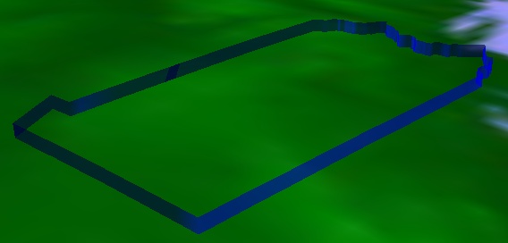
The surface and wall triangulators can take their input from boundaries computed from surface shapes. Surface shapes compute boundaries for areas on the surface such as ellipses and rectangles. They enable the triangle mesh to render these areas filled and the polyline to render the area's boundary. The pipeline of surface shapes, triangulators and primitives is shown below.
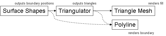
When fill is not required, positions from surface shape computations can be input to the polyline primitive to render just the boundary. When fill is used, the boundary from the triangulator should be input to the polyline. In many cases, the boundary computed by the triangulator will be different than the boundary input to the triangulator. By allowing the triangulator to add detail to the boundary, the triangulator can guarantee that the boundary it outputs precisely lines up with the triangle mesh it computed. This results in a watertight connection between the boundary and the mesh.
The following code example uses surface shapes to compute the boundary for a circle. The object is then input to the surface triangulator, which outputs triangles for the triangle mesh and a boundary for the polyline.
Cartographic center = new Cartographic(Trig.DegreesToRadians(39.88), Trig.DegreesToRadians(-75.25), 0);
SurfaceShapesResult shape = SurfaceShapes.ComputeCircleCartographic(earth, center, 10000);

SurfaceTriangulatorResult triangles = SurfacePolygonTriangulator.Compute(earth, shape.Positions);

TriangleMeshPrimitive mesh = new TriangleMeshPrimitive(SetHint.Infrequent);
mesh.Set(triangles);
mesh.Color = Color.White;
mesh.Translucency = 0.5f;

PolylinePrimitive line = new PolylinePrimitive(SetHint.Infrequent);
line.Set(triangles.BoundaryPositions);
line.Width = 2.0f;

SceneManager.Primitives.Add(mesh);
SceneManager.Primitives.Add(line);
In addition to triangulator objects, the triangle mesh can be initialized using an indexed triangle list representation of a triangle mesh. First, we describe the motivation and data structures for indexed triangle lists. Then, code examples are provided.
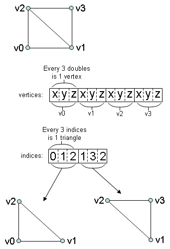
A naive way to represent a mesh in memory is an collection of vertices (x, y, z triplets), where every three vertices represents one triangle. This is referred to as triangle soup and is grossly inefficient in terms of memory usage and GPU vertex cache awareness.
Since most triangles in a mesh are connected to other triangles in a mesh, the preferred representation is the indexed triangle list. All of the unique vertices in the mesh are stored in an collection. A second collection contains indices of vertices in the first collection. Every 3 indices represents 1 triangle. Since the size of an index (typically 2 or 4 bytes) is much less than the size of a vertex (typically 12 or 24 bytes), less memory is used compared to triangle soup representations. Furthermore, Insight3D is capable of organizing the indices and vertices to get the best performance out of GPU vertex caches, which improves rendering performance.
Technical Details: Insight3D's vertex cache optimization is based on the 2007 SIGGRAPH paper Fast Triangle Reordering for Vertex Locality and Reduced Overdraw. |
An indexed triangle list for a mesh with two triangles is shown below:
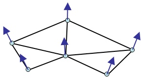
For proper lighting, meshes must have surface normals defined for each vertex. A surface normal is a vector of unit length that is perpendicular to the surface at that point as shown below.
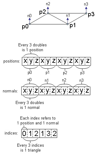
Normals are computed in a variety of ways. A straightforward algorithm to compute a normal for a position is to normalize the average the cross products of all adjacent incident edges to that position. Once computed, normals should be stored in a separate collection that has a one-to-one mapping with the position collection. The normal at index i in the normal collection is the normal for the position at index i in the position collection as shown below.
The following code example creates a triangle mesh with two triangles. The normals are the surface normals of the ellipsoid when the vertex is projected onto the surface.
Cartographic p0 = new Cartographic(Trig.DegreesToRadians(-5), Trig.DegreesToRadians(-5), 75000);
Cartographic p1 = new Cartographic(Trig.DegreesToRadians(5), Trig.DegreesToRadians(-5), 75000);
Cartographic p2 = new Cartographic(Trig.DegreesToRadians(-5), Trig.DegreesToRadians(5), 75000);
Cartographic p3 = new Cartographic(Trig.DegreesToRadians(5), Trig.DegreesToRadians(5), 75000);

Ellipsoid shape = CentralBodiesFacet.GetFromContext().Earth.Shape;
List<Cartesian> positions = new List<Cartesian>
{
    shape.CartographicToCartesian(p0),
    shape.CartographicToCartesian(p1),
    shape.CartographicToCartesian(p2),
    shape.CartographicToCartesian(p3),
};

List<Cartesian> normals = new List<Cartesian>
{
    Ellipsoid.SurfaceNormal(p0),
    Ellipsoid.SurfaceNormal(p1),
    Ellipsoid.SurfaceNormal(p2),
    Ellipsoid.SurfaceNormal(p3),
};

List<int> indices = new List<int>
{
    0,
    1,
    2,
    1,
    3,
    2,
};

TriangleMeshPrimitive mesh = new TriangleMeshPrimitive(SetHint.Infrequent);
mesh.Set(positions, normals, indices);
mesh.Wireframe = true;

SceneManager.Primitives.Add(mesh);