Platforms and Antennas |
In order to represent antennas in the Communications Library, Platforms are used to specify the position and orientation while an ObjectExtension defines the transmit and receive functionality, making the Platform a functional antenna. Though a Platform can also be used to describe a spacecraft or ground facility, the Platforms used here represent the antennas themselves. So, if the user wants to define an antenna with respect to a spacecraft, two Platforms will be involved unless the position and orientation are identical.
The functionality described in this topic requires a license for the Communications Library. |
RadioFrequencyTransmittingAntennaExtension takes a SignalProcessor, to define the signal to transmit from the antenna, and a RadioFrequencyGainPattern, to define the antenna gain as a function of the angle of transmission with respect to the boresight (z-axis) of the Platform. When a wireless link asks its transmitter for a set of signals to propagate, the link feeds its geometry to the RadioFrequencyTransmittingAntennaExtension and gets a set of signals with the appropriate gain applied.
RadioFrequencyReceivingAntennaExtension produces a SignalProcessor to represent the output of the antenna. When that output is evaluated, the extension asks the SignalPropagationGraph for all the links containing the extension's Owner (get). From this list, the extension looks for the AccessConstraintsExtension and the AccessResultExtension (precomputed access) to determine when each link is able to produce signals. Then, it obtains the geometry from each link, applies the RadioFrequencyGainPattern to the corresponding signals, and adds any antenna noise onto the signals before producing them as output. The NoiseTemperature (get) on the signals coming out of the antenna extension represents the equivalent noise temperature of the incoming signal plus the noise temperature of the antenna itself.
// Set up a platform to use as an antenna
Platform xmtrLosAngeles = new Platform();
xmtrLosAngeles.setLocationPoint(new PointCartographic(earth, losAngelesCoordinates));
xmtrLosAngeles.setOrientationAxes(new AxesVehicleVelocityLocalHorizontal(earth.getInertialFrame(), xmtrLosAngeles.getLocationPoint()));

// Choose a gain pattern for the antenna
GaussianGainPattern antennaPattern = new GaussianGainPattern();
antennaPattern.setDiameter(1.0); // meters
antennaPattern.setEfficiency(0.55); // ratio between zero and one
antennaPattern.setBacklobeGain(0.001); // Watts (-30 dBW)

// Create an extension to make the "uplinkXmtrAntenna" Platform into an antenna
RadioFrequencyTransmittingAntennaExtension transmitterAntenna = new RadioFrequencyTransmittingAntennaExtension();
transmitterAntenna.setAntennaGainPattern(antennaPattern);
transmitterAntenna.setInputSignalProcessor(signalProcessor);

// Add the extension to the antenna Platform
xmtrLosAngeles.getExtensions().add(transmitterAntenna);

// Create a platform for the receiver
Platform rcvrPhiladelphia = new Platform();
rcvrPhiladelphia.setLocationPoint(new PointCartographic(earth, philadelphiaCoordinates));
rcvrPhiladelphia.setOrientationAxes(new AxesEastNorthUp(earth, rcvrPhiladelphia.getLocationPoint()));

// Create a receiving extension for the "downlinkRcvrAntenna" Platform
RadioFrequencyReceivingAntennaExtension receiverAntenna = new RadioFrequencyReceivingAntennaExtension();
// Use the same gain pattern as above or specify a new one
receiverAntenna.setAntennaGainPattern(new IsotropicGainPattern());
receiverAntenna.setAntennaNoiseTemperature(290.0); // 290 Kelvin equivalent thermal noise
rcvrPhiladelphia.getExtensions().add(receiverAntenna);
// Connect signal processors to the antenna output
ConstantGainAmplifier amplifier = new ConstantGainAmplifier();
amplifier.setInputSignalProcessor(receiverAntenna.getOutputSignalProcessor());
DME Component Libraries computes polarization efficiency, which is a quantity between a transmitter and a receiver based on their polarization types, positions, and attitudes. To calculate the polarization efficiency, the angle between the transmitter's and receiver's E-field vectors in the plane perpendicular to the line of sight is computed. This angle is then used to rotate the Poincaré sphere representation of the transmitter in the receiver's coordinate system. The polarization efficiency is calculated dynamically on a scale of 0 to 1, where 0 is no match and results in no received signal, and 1 is perfect (no loss). To allow for cross polarization leakage, the minimum polarization efficiency is controlled by the CrossPolarizationLeakage (get / set) property of the RadioFrequencyReceivingAntennaExtension or OpticalReceivingAntennaExtension. So, for example, if the source polarization is left hand circular and the receive polarization is right hand circular, the polarization efficiency will be evaluated as the cross polarization leakage value.
Reference: See Kraus, John D., Antennas, 2nd ed., New York: McGraw-Hill (1988), pp. 70-73. |
In order to model signal power loss due to polarization efficiency between the transmitter and receiver antennas, a PolarizationSource can be configured on the RadioFrequencyTransmittingAntennaExtension or OpticalTransmittingAntennaExtension and the RadioFrequencyReceivingAntennaExtension or OpticalReceivingAntennaExtension. The polarization efficiency will only be accounted for if both the transmit antenna and the receive antenna are configured with a PolarizationSource. The library contains several PolarizationSource types which provide an evaluator for evaluating polarization over time based on link geometry and signal properties:
ConstantPolarizationSource - Produces a constant polarization, regardless of the link geometry.
Ieee1979PolarizationSource - Produces polarization based on the link geometry and measured antenna test data based on the IEEE 149 standard adopted in 1979.
FrequencyDependentElectricFieldPolarizationSource - Produces polarization based on the link geometry and a collection of frequency dependent electric field patterns.
AnsysHfssFarFieldDataPolarizationSource - Produces polarization based on data loaded from an Ansys HFSS far field data formatted file (*.ffd).
Polarization is a property of an electromagnetic wave that describes the orientation of the electric field vector with reference to the antenna's orientation. The three basic types of polarization are illustrated in the following figure:
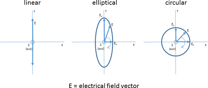
In the illustration of linear polarization, the electrical field is polarized in the y direction in the coordinate system. In special cases of linear polarization, the electrical field is aligned vertically or horizontally with reference to the antenna. In the other two types of orientation shown, the tip of the E vector describes an ellipse and a circle, respectively, as it rotates over time. Circular polarization can be right-handed or left-handed (as in the illustration).
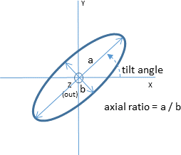
The following figure illustrates tilt angle and axial ratio for the elliptical polarization type:
// Set up a platform to use as an antenna
Platform xmtrLosAngeles = new Platform();
xmtrLosAngeles.setLocationPoint(new PointCartographic(earth, losAngelesCoordinates));
xmtrLosAngeles.setOrientationAxes(new AxesVehicleVelocityLocalHorizontal(earth.getInertialFrame(), xmtrLosAngeles.getLocationPoint()));

// Choose a gain pattern for the antenna
GaussianGainPattern antennaPattern = new GaussianGainPattern();
antennaPattern.setDiameter(1.0); // meters
antennaPattern.setEfficiency(0.55); // ratio between zero and one
antennaPattern.setBacklobeGain(0.001); // Watts (-30 dBW)

// Create an extension to make the "uplinkXmtrAntenna" Platform into an antenna
RadioFrequencyTransmittingAntennaExtension transmitterAntenna = new RadioFrequencyTransmittingAntennaExtension();
transmitterAntenna.setAntennaGainPattern(antennaPattern);
transmitterAntenna.setInputSignalProcessor(signalProcessor);
transmitterAntenna.setPolarizationSource(new ConstantPolarizationSource(new RightHandCircularPolarization()));

// Add the extension to the antenna Platform
xmtrLosAngeles.getExtensions().add(transmitterAntenna);

// Create a platform for the receiver
Platform rcvrPhiladelphia = new Platform();
rcvrPhiladelphia.setLocationPoint(new PointCartographic(earth, philadelphiaCoordinates));
rcvrPhiladelphia.setOrientationAxes(new AxesEastNorthUp(earth, rcvrPhiladelphia.getLocationPoint()));

// Create a receiving extension for the "downlinkRcvrAntenna" Platform
RadioFrequencyReceivingAntennaExtension receiverAntenna = new RadioFrequencyReceivingAntennaExtension();
// Use the same gain pattern as above or specify a new one
receiverAntenna.setAntennaGainPattern(new IsotropicGainPattern());
receiverAntenna.setAntennaNoiseTemperature(290.0); // 290 Kelvin equivalent thermal noise
receiverAntenna.setPolarizationSource(new ConstantPolarizationSource(new LinearPolarization()));
rcvrPhiladelphia.getExtensions().add(receiverAntenna);
// Connect signal processors to the antenna output
ConstantGainAmplifier amplifier = new ConstantGainAmplifier();
amplifier.setInputSignalProcessor(receiverAntenna.getOutputSignalProcessor());