Part 13:
Perform Trade Studies with Analyzer
This training requires additional licenses to complete. You can obtain the necessary license for the training by visiting http://licensing.agi.com/stk/evaluation or calling AGI support.
STK Analyzer
The STK Analyzer ( ) module is an integrated software
solution that automates STK trade studies and parametric analyses by blending the
engineering analysis capabilities of Phoenix Integration, Inc.'s ModelCenter with
STK.
) module is an integrated software
solution that automates STK trade studies and parametric analyses by blending the
engineering analysis capabilities of Phoenix Integration, Inc.'s ModelCenter with
STK.
Analyzer enables STK users to easily perform trade and optimization studies,
as well as post-processing functions. The Analyzer module provides the tools to
understand the design space of your system through an easy-to-use GUI style interface,
eliminating the need for scripts or programming. STK Analyzer provides a set of
analysis tools that:
- Enable you to understand the design space of your systems.
- Enable you to perform analyses in STK easily without involving programming or scripting.
- Introduce trade study and post-processing capabilities.
Analyzer has its own toolbar! Just right-click in the toolbar area and enable the
Analyzer toolbar from the drop down. On the toolbar, you'll find buttons to open
Analyzer, the Parametric Study tool, and the ability to open previously generated
trade studies.
Perform a Trade Study
Watch the following video, then follow the steps below incorporating the systems and missions you work on (sample inputs provided).
- Create a new scenario.

- Click the Create a Scenario (
 ) button.
 - In the New Scenario Wizard, set the following options:
- Enter a Name for the scenario (e.g. STK_Analyzer).
- Define the analysis start and stop times or accept the defaults.
- Click OK.
- Insert a facility (
 ) (e.g. using the Insert Default method).
 - Insert a satellite (
 ) using the Define Properties method.
 - On the Basic - Orbit page, adjust the Inclination to orbit over the facility (e.g. 40 deg).
- Click OK to accept the default parameters and dismiss the Properties Browser.
- Insert a Sensor (
 ) on the Satellite (e.g. using the default method).
- Generate an Access (
 ) report.
 - Open the Access tool ()l.
- On the Access panel, click the Select Object... button and select the sensor on the moving vehicle (e.g. satellite1-Sensor1) as the Access For object ("From").
- Select the ground site as the "To" object (e.g. Facility).
- In the Reports field, click the Access button. This will compute access, and generate an Access report.
If your report says "No Access Found," modify your vehicle properties so that the vehicle has access to the ground site.
- In the Timeline View toolbar, click the Add Time Components (
 ) button.
- If your Timeline View is not open, extend the STK View menu and select Timeline View.
- Select the Access (
 ) object.
 - Select AccessIntervals in the Components for section.
- Click OK to add the Access Intervals to the Timeline View and dismiss the Add Time Components tool
In STK 11.3 Access Intervals are automatically added to the Timeline. But if you are using an older version of STK, you can add them manually to the Timeline.
- Define Analyzer variables
- Extend the Analysis menu, extend the Analyzer menu, and select Analyzer ().
- Select one or more input variables
- Select the moving vehicle (e.g. Satellite1) in the STK Variables list.
- Click on the variable (e.g. Propagator (TwoBody) in the STK Property Variables General tab.
- Move or double-click the name to add it to the Analyzer Variables field.
- Repeat the previous step until all desired input variables are in the Analyzer Variables field.
- Select one or more output variables
- Expand Access in the STK Variables list and select the moving vehicle - sensor to ground site access.
- Expand the data provider (e.g. Access Data) in the Data Provider variables tab.
- Select the desired variable (e.g. expand Duration and select sum) and move or double-click the name to add it to the Analyzer Variables field.
- Repeat the previous step until all desired output variables are in the Analyzer variables field.
- Design a Parametric trade study.
- Click the Parametric Study (
 ) button on the STK Analyzer window to open the Parametric Study dialog.
 - Define the Design Variables.
- Click and drag the desired input variables (e.g. SemiMajorAxis) in the Components list and drop it in the design variable (
 ) box.
 - In the Design Variable text fields, enter the desired values.
(e.g: 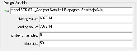 )
)
- Define the Responses
- Click and drag the desired response variable (e.g. Access_Data Duration sum) in the Components list and drop it in the Responses section.
- Click Run... to run the study and watch the 2D and 3D Graphics windows and Timeline View change with each iteration.
- Create a Carpet Plot trade study.
- Click the Carpet Plot (
 ) button on the STK Analyzer window to open the Carpet Plot tool dialog.
 - Define the Design Variables.
- Click and drag the desired input variables (e.g. SemiMajorAxis and Inclination) in the Components list and drop it in the design variable ()
- In the Design Variable text fields, enter the desired values.
(e.g: 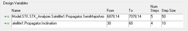 )
)
- Define the Responses
- Click and drag the desired response variable (e.g. Access_Data Duration sum) in the Components list and drop it in the Responses section.
- Click Run... to run the study and watch the 2D and 3D Graphics windows and Timeline View change with each iteration.
Don't forget to save your work!
 Visit AGI.com