Part 9:
Create an AzEl Mask from a 3D Model
This training requires additional licenses to complete. You can obtain the necessary license for the training by visiting http://licensing.agi.com/stk/evaluation or calling AGI support.
AzEl Mask Tool
The AzEl Mask tool generates static body masking (*.bmsk) files which are used to restrict visibility to a sensor. The term body masking refers to line-of-sight obstruction caused by the three-dimensional model of the parent object of the sensor or other objects in the scenario. The body masking files contain obscuration contours which are generated based on six views generated from the point of view of an observer at the location of the sensor.
The six views can be thought of as containing projections of the obscuration objects onto the faces of a cube centered at the sensor. Contours are constructed using an edge detection algorithm and stored along with information describing the orientation of the view from which they were constructed. To affect visibility computations, set the body masking file as the AzEl Mask file for the sensor and enable the sensor AzEl Constraint. You can combine the terrain obsuration from the Add Fidelity with STK Pro exercise with 3D model obscuration.
Create a Sensor AzEl Mask
Watch the following video, then follow the steps below incorporating the systems and missions you work on (sample inputs provided).
- Create a new scenario with the default time period.

- Click the Create a new scenario (
 ) button.
 - In the New Scenario Wizard, set the following options:
- Enter a name for the scenario (e.g. STK_SensorAzElMasking).
- Use the default Start time.
- Set the Stop time to one (1) second.
- Click OK.
- Add visual and analytical terrain to the scenario.
- Right-click on SensorAzElMasking () and select Properties (
 ).
). - Select the Basic - Terrain page.
- Disable the Use Terrain Server for analysis option.
- Click OK to apply the changes and dismiss the Properties Browser.
- In the 3D Graphics window toolbar, click the Globe Manager (
 ). You can also extend the View menu and select Globe Manager.
 You can drag and drop .pdtt files directly onto the STK globe.
- Click the Add Terrain/Imagery (
 ) button or right-click Earth in the Globe Manager and select Add Terrain/Imagery.
 - Ensure Local Files is selected.
- Click the ellipsis (
 ) button and browse to C:\Program Files\AGI\STK 11\Help\stkTraining\Imagery.
 - Open StHelens_Training.pdtt.
- When prompted, click Yes to enable terrain for analysis.
- Right-click on the *.pdtt file in the Globe Manager and select Zoom To.
- Ensure a ground site considers terrain.
- Model a Place (
 ) object on the terrain region using the From City Database method.
 - Insert Morton, Washington using the From City Database option.
- Ensure Morton considers terrain height for its altitude.
- Right-click on Morton () and select Properties ().
- Select the Basic - Position page.
- Ensure the Use terrain data for altitude option is enabled.
- Enter 20 ft (feet) in the Height Above Ground field.
- Click Apply.
- Define an Azimuth-elevation mask and use it for an access constraint.
- Select the Basic - AzElMask page.
- Enable the Use Terrain Data option.
- Enable the Use Mask for Access Constraint option.
- Click OK to apply the changes and dismiss the Properties Browser.
- Model a sensor on Morton
- In the Insert STK Objects (
 ) tool, select Sensor (
 .
. - Select Insert Default as the Select A Method option.
- Click the Insert... button to bring the Select Object window to the front.
- Select Morton in the Select Object window.
- Click OK.
- Rename the sensor SatTracker.
- Ensure SatTracker properties uses the parent object's AzElMask file.
- Right-click on SatTracker () and select Properties ().
- Select the Basic - Definition page.
- Set the Sensor Type to Complex Conic.
- Set the Half Angles - Outer to 180 deg.
- Click Apply.
- Select the Constraints - Basic page.
- Enable the Az-El Mask option.
- Click Apply.
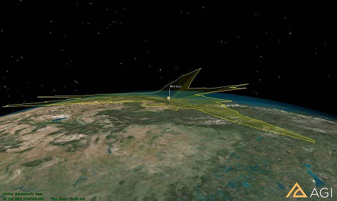
- Display Terrain Obscuration.
- Select the 2D Graphics – Projection page.
- In Field of View, enable Use Constraints.
- Select AzElMask.
- Click Apply.
- Select the 3D Graphics – Projection page.
- Set Space Projection to 50km.
- Click OK to apply the changes and dismiss the Properties Browser.
- Zoom To Morton and use the mouse to view the AzElMask constraints.
- Model an obscuring object.
- In the Insert STK Objects tool, select Facility (
 .
. - Select Insert Default as the Select A Method option.
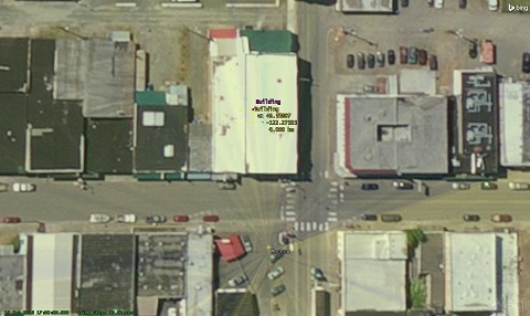
- Rename the Facility object “Building.”
- Zoom To Morton ().
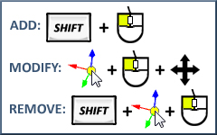
- Use the 3D Object Editing tool to place Building in the middle of the white structure across the street from Morton.
- Create a Sensor AzEl Mask.
- Right-click on SatTracker () and extend the Sensor menu.
- Select the AzEl Mask option.
- In the AzEl Mask tool, locate the Obscuring Objects field and select Building.
- In the File: field, click the ellipsis () button.
- Ensure the path goes to your scenario folder.
- Enter MyBodyMask in File Name.
- Click Save.
- Change Window Dim: to 500.
- Click Apply.
- Ensure the AzEl Mask tool is not obstructing the Az/El Mask View window.
- Click Compute.
- Close the AzEl Mask tool and the Az/El Mask View window.
- Ensure the Sensor uses the body mask file (*.bmsk) during access calculations.
- Right-click on SatTracker () and select Properties ().
- Select the Basic – Sensor AzEl Mask page.
- Enable the Use MaskFile option.
- Click the Mask File: ellipses () button.
- Select MyBodyMask.bmsk and click Open.
- Enable the Use Mask for Access Constraint option.
- Click Apply.
- Display Body Mask File Obscuration.
- Select the 2D Graphics – Projection page.
- In Field of View, use the Ctrl key to select SensorAzElMask and ensure AzElMask is still selected.
- Click OK to apply the changes and dismiss the Properties Browser.
- Zoom To Building and view the obscuration.

Don't forget to save your work!
 Visit AGI.com