Part 8:
Add Fidelity with STK Pro
This training requires additional licenses to complete. You can obtain the necessary license for the training by visiting http://licensing.agi.com/stk/evaluation or calling AGI support.
STK Pro introduces more sophisticated modeling through advanced access constraints, flexible sensor shapes, complex visibility links, more object tracks, and digital terrain data. STK Pro allows users to:
- Constrain model behavior based on motion and geographic limitations including analytical and visual terrain.
- Define advanced sensor fields-of-view and fields-of-regard using custom geometry and pointing.
- Build system networks using defined groups or sequential, multi-link relationships called "chains".
Analytical and Visual Terrain
AGI works with several sources of terrain data. When used with STK, terrain
exploits sophisticated multi-dimensional interpolation algorithms to provide accurate
360 degree azimuth-elevation masks for access calculations from any point on the
Earth's surface. These algorithms also provide altitude information for user-defined
facilities, places, and targets. Terrain, when used visually, allows a vivid 3D visual depiction
of the Earth's true surface relief and its effect on accesses and visibility. Terrain, when used for analysis, includes terrain elevation data in the
computation of an azimuth-elevation mask; the position of a facility,
place or target; altitude reference for an aircraft, facility, place, ship, or target;
height above ground for a facility, place or target; boundary wall for an area target
or line target.
Add Terrain and Imagery to Determine its Impact on Line of Sight Visibility
Watch the following video, then follow the steps below incorporating the systems and missions you work on (sample inputs provided).
- Add Terrain and Imagery

- Create a new scenario with the default time period.
- Click create a Scenario (
 ).
). - In the New Scenario Wizard set the following options:
- Name the scenario (e.g. "STK_Pro").
- Define the analysis start and stop times or accept the defaults.
- Add analytical terrain to the scenario.
- Right-click on the scenario () and open the Properties (
 ).
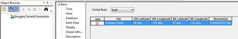
). - Select the Basic - Terrain page.
- Disable the Use terrain server for analysis option.
- Click the Add button and browse to the terrain data file (e.g. hoquiam-e.dem).
- The example file is located at <Install Directory>\Help\stktraining\samples
- Click OK to apply changes and dismiss the Properties Browser.
- Convert the terrain data file to a terrain inlay file (*.pdtt).
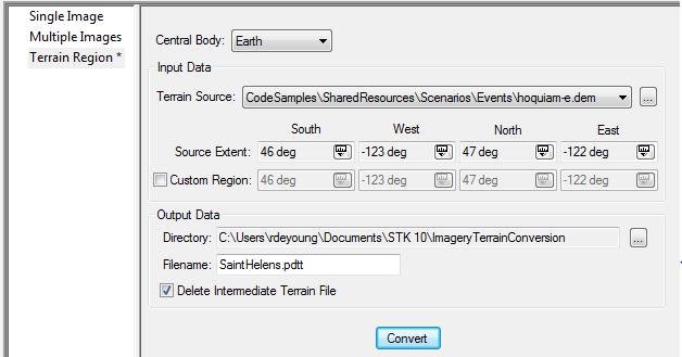
- Click the Utilities menu and select Imagery and Terrain Coverter...
- Select the Terrain Region page.
- Select the Terrain Source previously loaded in the scenario from the drop-down list (e.g. hoquiam-e.dem).
- Click the ellipsis (
 ) button to select the Output Data Directory (e.g. current scenario directory).
 - Enter a filename (e.g. SaintHelens) in the Filename text field.
- Click Convert.
- Click Close to dismiss the Imagery and Terrain Converter.
- Add visual terrain to the scenario.
- Click the Globe Manager (
 ) icon or click the View menu and select Globe Manager.
 You can drag and drop .pdtt files directly onto the STK globe.
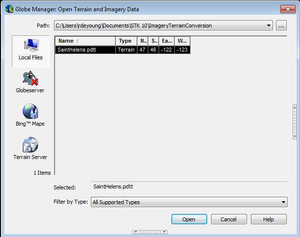
Click the Add Terrain/Imagery ( ) button or right-click Earth in the Globe Manager and select Add Terrain/Imagery...
- Select the *.pdtt file (e.g. SaintHelens.pdtt) from the Path drop-down list.
- Click Open.
- When prompted, click Yes to enable terrain for analysis.
- Right-click on the *.pdtt file in the Globe Manager and select Zoom To.
- Ensure that Ground Sites Consider Terrain.
- Model a ground site (any type:
 ,
, ,
,  ) on the terrain region using one of the available insert methods (examples below)..
- Insert a Place () and Search by Address (requires Internet (
 ) (e.g. Mount St. Helens, WA).
 - Insert a ground site (any type: ,, ) on the terrain region by using 3D Object Editing.
- Ensure the ground site (any type: ,, ) considers terrain height for its altitude.
- Right-click on the ground site (e.g. Mount_St_Helens_WA) and select Properties ().
- Select the Basic - Position page.
- Enable the Use terrain data for altitude option.
- Click OK to apply the changes and dismiss the Properties Browser.
- Create and Display Terrain Obscuration.
- Right-click on the ground site (e.g. Mount_St_Helens_WA) and select Properties ().
- Define an azimuth-elevation mask and use it for an access constraint.
- Select the Basic - AzElMask page.
- Use Terrain Data.
- Enable Use Mask for Access Constraint.
- Click Apply to apply the changes and keep the Properties open.
- Display the azimuth-elevation mask at the ground site.
- Select the 2D Graphics - AzElMask page.
- Enable the Show option beside the At Range option.
- Enter a max range for the mask display (e.g. ten (10) km).
- Click OK to accept the changes.
- Mouse around the 3D Graphics window to take a look at the azimuth-elevation mask display.
- Ensure a Moving Vehicle Considers Terrain.
- From the Insert STK Objects (
 ) tool, select Ground Vehicle (
 ) and choose the Define Properties method.
 - Ensure the vehicle considers terrain along its route.
- Select the Basic - Route page.
- Select Terrain as the Altitude Reference.
- Set a Granularity type (e.g. 0.01 km).
- Select Terrain Height as the Interp Method.
- Insert waypoints (examples below):
- Type in waypoint values.
- On the Basic - Route page, click Insert Point twice to add two waypoints manually.
- Enter values for the first waypoint (e.g. Lat = 46.23 deg, Lon = -122.23 deg).
- Enter values for the second waypoint (e.g. Lat = 46.19 deg, Lon = -122.13 deg).
- Click OK to dismiss the Properties browser.
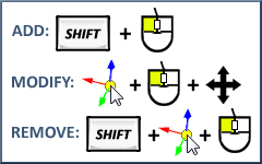
- Click the waypoints in the 3D window.
- Make sure the ground vehicle's Properties Browser is closed.
- Use the 3D Object Editing tool to model the ground vehicle's route.
- Determine if Terrain is Obscuring the View.
- Compute Access (
 ) between the ground station () and ground vehicle () and generate an Access report.
 - Open the Access () tool.
- On the Access page, click the Select Object... button and select the ground site (e.g. Mount_St_Helens_WA) as the Access For object (From).
- Select the ground vehicle () as the To object.
- Click the Compute button.
- Click Access... in the Reports section of the Access tool.
- Add intervals (
 ) to the Timeline View.
 - In the Timeline View toolbar, select Add Time Components (
 ).
). - Add the ground vehicle's availability time span to the Timeline View.
- Select the Ground Vehicle () on the left.
- Select AvailabilityTimeSpan in the Components for section on the right.
- Click Apply to add the availability interval to the Timeline View.
- Add the access intervals to the Timeline View.
- Select the Access object on the left.
- Select AccessIntervals in the Components for section on the right.
- Click OK to add the Access Intervals to the Timeline View and dismiss the Add Time Components tool.
- Center Timeline View on the availability time span.
- Right-click on the availability time span interval.
- Select Center.
- Animate (
 ) and mouse around the 3D Graphics window to visualize when the terrain obstructs access.
 - Use the Slide Bar to scroll through the ground vehicle's route and visualize when the terrain obstructs access.
Don't forget to save your work!
 ) objects in STK. Chains model a list of objects (either individual or grouped into Constellations (
 ) in order of access.
 ) by searching the Standard Object Database (e.g. ANIK F2).
 ) the first object in the chain (e.g. Mount_St_Helens_WA) to the Available Objects list.
 Visit AGI.com