In the following tutorial, you will analyze communications network performance between a convoy and a UAV relay as the convoy traverses a valley road.
- You will use STK to model the dynamic positions of each asset, consider their antenna pointing, and compute link budget information between the UAV and the ground vehicle radio operator.
- You will use the QualNet Interface to analyze network performance throughout the mission.
This tutorial guides you through creating STK objects that are then imported into the QualNet Interface. An alternative method, which is not part of this tutorial, is to import wireless interfaces from the QualNet configuration directly into the QualNet Interface. To learn more about importing wireless interfaces, see Importing a QualNet Configuration File.
- The QualNet Interface for STK Communications, which requires an STK Communications license to use, is installed from the QualNet Interface install medium to your STK install area.
- QualNet 5.0.2 or later software from Scalable Network Technologies must be installed and licensed on your computer.
- This tutorial requires a basic knowledge of how to use STK, including creating and populating a scenario, setting up 3D visualization, animating a scenario, and running a Link Budget report. If you are a new STK user, follow Beginner tutorials to learn the basics of STK before attempting to perform the steps in this tutorial.
- All external files required for this tutorial are located in <STK install folder>/Help/stktraining/samples/qualNetInterfaceTutorial. On machines with a 32-bit operating system, the default install area for STK 11 is: C:/Program Files/AGI/STK 11/.
The results of the tutorial may vary depending on the user settings and data enabled (online operations, terrain server, dynamic Earth data, etc.). It is acceptable to have different results.
Define the Physical Layer Using STK
High-fidelity modeling of the physical layer is one of STK's strengths. STK is a physics-based software geometry engine that accurately models the time-dynamic position and orientation of vehicles, the characteristics and pointing of sensors and communications assets, and the spatial relationships (e.g., line of sight) between objects.
Create a Scenario
- Create a scenario for the following analysis period:
- There is a 25-second start time difference between each ground vehicle that will be added to this scenario. To see all ground vehicles at the start of animation, change the Animation Start Time on the scenario's Basic->Time properties page to:
- Save the scenario.
Start Time: 1 Mar 2010 08:00:00.000 UTCG
Stop Time: 1 Mar 2010 08:40:00.000 UTCG
1 Mar 2010 08:01:15.000 UTCG
Add Terrain and Imagery to your Scenario
To add the sample terrain file and imagery for enhanced 3D visualization:
- Select the 3D Graphics window, click
 to open the Globe Manager window, and click
  on the Globe Manager toolbar to display the Open Terrain and Imagery Data window.
 - Browse to <STK install area>/Help/stktraining/samples/qualNetInterfaceTutorial. Multi-select SWalesHiRes.pdtt and STKQualnet.pdttx and click Open. The files will be displayed in the Globe Manager window.
- In the Globe Manager, right-click SWalesHiRes.pdtt and select Zoom to to view the terrain and imagery in the 3D Graphics window.
Populate the Scenario
To model the mission, populate the scenario with the following objects:
To save steps when defining vehicle routes, this tutorial uses the StkExternal propagator, which enables you to import the position and velocity for a vehicle directly from an ephemeris file.
UAV Aircraft
- Add a default Aircraft object, change its name to UAV, and open up its properties.
- Select StkExternal as the propagator.
- In the Filename field under Ephemeris Type, browse to <STK install area>/Help/stktraining/samples/qualNetInterfaceTutorial/UAV.e.
- Go to the UAV's Basic->Attitude page. Under Precomputed, select Override Basic & Target Pointing Attitude for specified times and in the File field, browse to <STK install area>/Help/stktraining/samples/qualNetInterfaceTutorial/UAV.a.
- Go to the UAV's 3D Graphics Model page. Click on the Model File ellipses button and select rq-1a_predator.mdl.
- To view the aircraft's route, select View From/To from the 3D Graphics window or zoom to the aircraft, adjust the animation time step to 1.00 sec, and click
 on the animation toolbar.
The ephemeris and attitude files used to define the UAV were created using the Aviator propagator. Aviator is an advanced propagator that creates a route using a sequence of curves parameterized by readily available performance characteristics of aircraft, including cruise airspeed, climb rate, roll rate, and bank angle. To learn more about modeling an aircraft using Aviator, see Aviator. To learn more about the various aircraft propagators available with STK, see The Aircraft Object.
STK also offers propagators for high-fidelity modeling of ground vehicles, launch vehicles, missiles, satellites, and ships.
Convoy
Use the StkExternal propagator and the default GroundVehicle object to easily create four trucks in the convoy. You select the propagator and ephemeris file on the ground vehicle's Basic->Route page. Define the ground vehicles as follows:
| Add Object... | Import Ephemeris File ... |
|---|---|
| GroundVehicle1 | <STK install area>/Help/stktraining/samples/qualNetInterfaceTutorial/mobile1.e |
| GroundVehicle2 | <STK install area>/Help/stktraining/samples/qualNetInterfaceTutorial/mobile2.e |
| GroundVehicle3 | <STK install area>/Help/stktraining/samples/qualNetInterfaceTutorial/mobile3.e |
| GroundVehicle4 | <STK install area>/Help/stktraining/samples/qualNetInterfaceTutorial/mobile4.e |
The ephemeris files for the GroundVehicles were created using the GreatArc propagator. The Great Arc Propagator defines vehicles that follow a point-by-point path over or below the surface of the Earth at a given altitude or depth.
Model Communications Assets
Use antenna objects attached to sensors to model your communications assets:
To track the convoy from the UAV:
- Add a default sensor to the UAV, name it UAVtoGV2, and change the following properties:
- On the sensor's Basic->Pointing page, set the Pointing Type to Targeted and add GroundVehicle2 to the Assigned Targets list.
- On the sensor's 3D Graphics->Attributes page, select Translucent Lines and set the Projection Translucency percentage to 100.
- Add a default antenna to the UAVtoGV2 sensor and name it UAVtoGV2antenna. (Note that antenna names carry over to the QualNet Interface.) Make the following property changes:
- On the Basic->Definition page:
- On the 3D Graphics->Attributes page:
- Select Show Volume under Volume Graphics to visually reinforce the targeting of the ground vehicle.
- Change Gain Scale to 0.001 km per dB.
- Under Elevation, change Resolution to 0.1 deg.
Type: Parabolic
Design Frequency: 14 GHz
Diameter: 0.762 m
Efficiency: 80 %
To define assets for communication between the convoy and the UAV:
- Copy the UAVtoGV2 sensor to GroundVehicle2, rename it GVtoUAV, and change the Pointing Type to Fixed on the GVtoUAV's Basic->Pointing page.
- Notice that the antenna is also copied. Rename it GVtoUAVantenna and change the following properties:
- On the Basic->Definition page:
- On the 3D Graphics->Attributes page, change Gain Scale to 0.01 km per dB.
Diameter: 0.24765 m
Efficiency: 55 %
To set up communications among the trucks in the convoy:
- Copy GVtoUAVantenna to GroundVehicle1, rename it WiFi1, and make the following changes:
- On the Basic->Definition page, change Design Frequency to 2.4 GHz.
- On the 3D Graphics->Attributes page, clear Show Volume under Volume Graphics.
- Copy WiFi1 to GroundVehicle2, GroundVehicle3, and GroundVehicle4. Rename the antennas as follows:
GroundVehicle2: WiFi2
GroundVehicle3: WiFi3
GroundVehicle4: WiFi4
To finish modeling the communications link between the UAV and convoy, we will use complex transmitter and receiver models to gain more insight into the performance of the wireless links. The complex model can reference an antenna object. Antenna objects are used in the definitions of QualNet interfaces.
- Add a default transmitter to GroundVehicle2, name it GVtoUAV_Xmtr, and change the following properties:
- Add a default receiver to the UAV, name it UAVtoGV2_Rcvr, and change the following properties:
Model Specs Tab
Type: Complex Transmitter Model
Frequency: 14 GHz
Power: -10 dBW
Antenna Tab
To link the transmitter to a fixed antenna:
Reference Type: Link
Antenna Name: Sensor/GVtoUAV/Antenna/GVtoUAVantenna
Model Specs Tab
Type: Complex Receiver Model
Auto Track: Disabled
Frequency: 14 GHz
Antenna Tab
To link the receiver to an antenna that is targeted to GroundVehicle2:
Reference Type: Link
Antenna Name: Sensor/UAVtoGV2/Antenna/UAVtoGV2antenna
Use the 3D Graphics Window to View Antenna Performance
The Antenna characteristics for each asset are defined based on performance specifications, pointing, and body location.
- Zoom to the UAV and animate the scenario to view the following in the 3D Graphics window:
- Antenna gain volume for the UAV receiver tracking the reported location of GroundVehicle2.
- Antenna pitch. The antenna can pitch from nadir to 5 deg off the UAV's XY-plane, where X points in the direction of the vehicle's ECF velocity vector, Z is aligned with the nadir direction, and Y forms a right-handed Cartesian coordinate system with X and Z. This affects communications availability depending on the UAV's current position and attitude.
- Zoom to GroundVehicle2 and animate the scenario to view the antenna gain volume for GroundVehicle2.
Perform Analysis on the Communications Links
The dynamic Link Budget is calculated based on each asset's current position, attitude, and (defined) transmitter and receiver parameters. You can display the Link Budget results dynamically in the 3D Graphics window or in a static report.
To dynamically display the receiver gain over the equivalent noise temperature (g/T), the bit energy to noise power spectral density ratio (Eb/No), and Bit Error Rate (BER) for the link between GroundVehicle2 and the UAV over time in the 3D Graphics window:
- Right-click GVtoUAV_Xmtr under GroundVehicle2 and select Access....
- Select UAVtoGV2_Rcvr under UAV in the Associated Objects list.
- Click 3D Graphics Displays....
- Click Add... and select Link Budget - BER.
- Minimize the Access window and animate the scenario to view the dynamic display.
To display the same data in a static report to determine the quality of the link between the UAV and the convoy:
- Restore the Access window.
- Click Report & Graph Manager ....
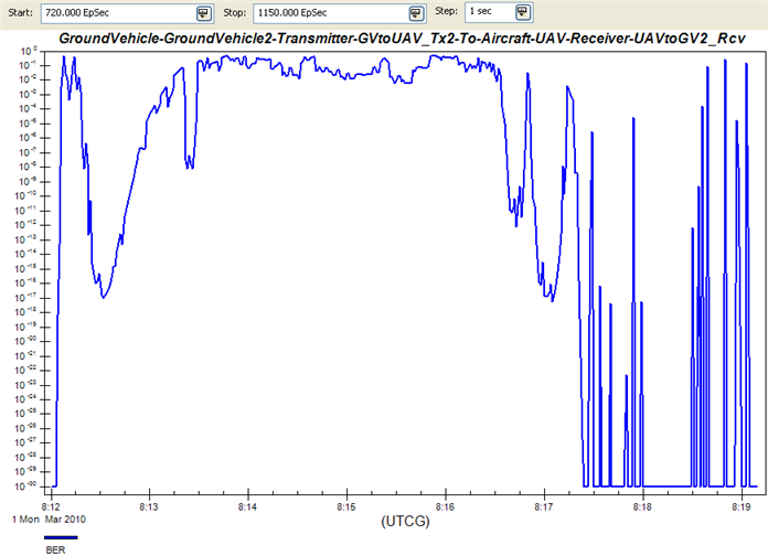
- Make sure that GroundVehicle-GroundVehicle2-Transmitter-GVtoUAV_Xmtr-To-Aircraft-UAV-Receiver-UAVtoGV2_Rcvr is highlighted in the window showing available links.
- Double-click Link Budget- Detailed under Installed Styles.
- In the Link Budget report, look at the BER for 1 Mar 2010 08:18:25, which is when the UAV is directly above GroundVehicle2, and the BER value is at its minimum. The report also shows that the link performs poorly at 1 Mar 2010 08:16:25, as the BER is many orders of magnitude greater than two minutes later.
- To find out why, enter 1 Mar 2010 08:16:25 in the Current Scenario Time field in the Animation toolbar to display the results in the 3D Graphics window. Notice the large angle between the direction of the link and the antenna boresight on the ground vehicle.
- Minimize the report. It will be used later in the tutorial.
- Close the Report & Graph Manager and Access windows.
We will take steps later in this tutorial to improve BER on the communications link.
You can also create an STK custom graph to illustrate the same problem area. The following graph shows the Link Information BER data provider over time. For more information on creating custom reports and graphs, see Generating Reports & Graphs.
Display the QualNet Interface Toolbar and Launch the QualNet Interface Scenario Explorer
Now that the physical objects are fully defined using STK, we can map those objects into the QualNet simulation using the QualNet Interface.
- Select Toolbars->QualNet Interface from the View menu to display the toolbar. The QualNet Interface toolbar enables you to access and interact with the QualNet Interface.
- Click
 to launch the QualNet Interface Scenario Explorer. It is very similar to the QualNet application GUI. The QualNet Interface Scenario Explorer contains an object tree and a properties pane.

These same QualNet Interface functions are also available from the Utilities menu.
Configure Your Scenario in the QualNet Interface
To define your scenario configuration:
- In the object tree, expand the Scenario Configuration folder and click General->General Settings. In the properties pane, notice that the Simulation Time of 2400S is inherited from the STK Scenario Analysis time. Also, notice that the Simulation Time is bolded. All values that are user-defined or inherited from STK are bolded.
- Select Channel Properties and expand Number of Channels. A second channel needs to be defined for communication between GroundVehicle2 and the UAV. To create that second channel, change the following channel properties:
- In the object tree, expand
 Hierarchy and verify that there is one node for each STK parent object in the STK scenario.
 - Define the following interfaces between STK antennas by right-clicking on a node and selecting Add->Network Interface.
Number of Channels: 2
Channel Frequency [1]: 14 GHz
| Node | Interface Name | Instance Name |
|---|---|---|
| UAV | UAVtoGV2 | UAVtoGV2/UAVtoGV2antenna |
| GroundVehicle2 | GV2toUAV | GVtoUAV/GVtoUAVantenna |
| GroundVehicle1 | GV1_Wifi | WiFi1 |
| GroundVehicle2 | GV2_Wifi | WiFi2 |
| GroundVehicle3 | GV3_Wifi | WiFi3 |
| GroundVehicle4 | GV4_Wifi | WiFi4 |
Create Connections Between QualNet Interfaces
Now that you have defined the interfaces between STK antennas, you can define your connections.
- Define the following connections by right-clicking on
 Connections and making the proper selection.
 - Set up the GV2toUAV wireless subnet so that it can only transmit and receive on the second channel, and that the Radio Type and MAC Protocol are appropriate for the large range of the link between the GroundVehicle and the UAV:
- For the Convoy wireless subnet, change the following parameters:
- For the CBR application, change the following parameters:
| Connection Type | Name | Parameters |
|---|---|---|
| Wireless Subnet | Convoy |
Move the following Available Interfaces to Selected Interfaces: Keep the default values for all other parameters. |
| Wireless Subnet | GV2toUAV | Move the following Available Interfaces to Selected Interfaces: UAV/UAVtoGV2 GroundVehicle2/GV2toUAV Keep the default values for all other parameters. |
| Application | n/a | Source: GroundVehicle4 Destination: UAV Application: CBR |
The Convoy and GV2toUAV are located under Connections->Wireless Subnets in the object tree. The application link you created is named CBR: GroundVehicle4-->UAV and is located under Connections->Applications.
Physical Layer
Listenable Channel Mask: 01 (only 14 GHz is selected)
Listening Channel Mask: 01 (only 14 GHz is selected)Radio Type: Abstract
Data Rate: 100 Mbps.Packet Reception Model
SNR Threshold: 0
MAC Layer
MAC Protocol: Generic MAC
Network Layer
Schedulers and Queues
Number of IP Output Queues: 1
Routing Protocol
Routing Protocol IPv4: AODV
Physical Layer
Listenable Channel Mask: 10 (only 2.4 GHz is selected)
Listening Channel Mask: 10 (only 2.4 GHz is selected)Radio Type: 802.11b Radio
TransmissionPower at 1 Mbps: 45 dBm
TransmissionPower at 2 Mbps: 45 dBm
TransmissionPower at 6 Mbps: 45 dBm
TransmissionPower at 11 Mbps: 45 dBm
Network Layer
Schedulers and Queues
Number of IP Output Queues: 1
Routing Protocol
Routing Protocol IPv4: AODV
Items to Send: 360
Start Time: 790 seconds
End Time: 1150 seconds
The Start and End Time settings allow you to focus on the section of the route where BER drops significantly, as indicated by the Link Budget report. The Items to Send value of 360 in combination with the 360 sec time period between Start Time and End Time, forces the application to send one packet per second.
Run a QualNet Experiment
Click ![]() to run a QualNet experiment. The status of the run is displayed in the progress bar. QualNet
Experiment files and optionally, an STK VDF file, are saved to the folder specified on the QualNet Interface preferences page, and the Stat File Viewer that shows the .stat file generated by the experiment is displayed. The statistical categories are listed in the object tree.
to run a QualNet experiment. The status of the run is displayed in the progress bar. QualNet
Experiment files and optionally, an STK VDF file, are saved to the folder specified on the QualNet Interface preferences page, and the Stat File Viewer that shows the .stat file generated by the experiment is displayed. The statistical categories are listed in the object tree.
If the Stat File Viewer does not display, click  to display the QualNet Command-line Output Log which lists all messages generated by the QualNet Experiment run. Correct any errors listed in the log and rerun the QualNet experiment.
Discussing the details of the network simulation is beyond the scope of this tutorial. This tutorial only highlights selected results.
Look at the statistics for the following categories:
Transport-> UDP
As you can see from the results, the UAV received only 140 packets from the 360 packets sent from GroundVehicle4.
- Packets from the Application Layer: 360
- Packets to the Application Layer: 140
Network->AODV for IPv4
These statistics show the number of times that the application tried to find a route from GroundVehicle4 to the UAV, the number of times there was no route available, and the number of packets dropped. Look at all the statistics in this category to determine if there are any network problems.
Look at Number of Data Packets Dropped for no route. The statistics show that the 220 data packets were dropped because the application could not find a route from GroundVehicle4 to the UAV.
Application->CBR Server
The First Packet Received statistics show that there was a long delay (around 1,000 seconds) before the first packet was received.
Close the Stat File Viewer.
Take Steps to Improve Communications
The QualNet statistics highlight a problem area on the route. This problem could indicate that the transmission power of the equipment needs to be increased or the orientation of the antenna on GroundVehicle2 needs to change.
There are two options that you can try:
Option 1 - Increase the Transmission Power of the Communications Device
- In the QualNet Interface, increase the Transmission Power to 34.7712 (dBm) on the GV2toUAV wireless subnet's Physical Layer.
- Rerun the QualNet experiment. Look at the same statistics. You will see that improvements were made in all areas. For example, the number of Packets from the Application Layer now equals the number of Packets to the Application Layer.
- Display the QualNet stat file from the first experiment run by clicking
 and selecting the appropriate .stat file. Each stat file is placed into a separate folder. Compare the results from the second experiment run with the first by flipping back and forth between the two Stat File Viewer windows.
Option 2 - Change the Orientation of GroundVehicle2 Antenna
- To test this option, reset the Transmission Power to 15 (dBm) on the GV2toUAV wireless subnet's Physical Layer.
- In STK, change the GVtoUAV sensor on GroundVehicle2 to a targeting sensor on the Basic->Pointing page. Change Pointing Type to Targeted and move UAV from the Available Targets list to the Assigned Targets list.
- In the QualNet Interface, rerun the QualNet experiment. Look at the same statistics. Again, you will see that improvements were made in all areas.
- Restore and refresh the Link Budget report. Look at the BER value for 1 Mar 2010 08:16:25 to verify that it improved.
- In STK, click
 and then to reset and run the animation, and view the improved performance of the communications link between GroundVehicle2 and the UAV in the 3D Graphics window.
 Visit AGI.com