Geostationary Belt Exclusion Angle | Height Above Horizon | Terrain Grazing Angle | Object Exclusion Angle | Elevation Rise-Set | CentralAngle/CentralDistance
Special Constraints
A number of special access constraints, described below, are available. You can also opt to exclude time intervals that satisfy a given constraint.
When an access involves a child object (i.e., sensor, transmitter, receiver, antenna, or radar), use the child object's parent or grandparent in the table below to determine whether the constraint can be used for access to that child object. For example, if a constraint can be used for accesses to all vehicles, then that constraint can also be used for any child object of a vehicle.
In the following table, abbreviations in the Constraints used for accesses to... column are:
| F = facility | Pl = place | T = target | V = all vehicles | S = satellite | M = missile | L = launch vehicle | G = ground vehicle |
| A = aircraft | Sh = ship | Sn = sensor | AT = area target | LT = line target | P = planet | St = star |
| Constraint | Description | Constraint used for accesses to... |
|---|---|---|
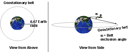
| Geostationary Belt Exclusion Angle |
The Geostationary Belt Exclusion Angle constraint is used to disallow access when the angle between the direction to the target object and the direction to any point of the geo belt is within the specified value. As of STK 11.x, Earth obstruction is modeled, so that only those points on the geo belt that are visible from the site's ground location are considered. This constraint is useful when calculating access from a facility, place, or target to a LEO satellite (see illustration below). The Geostationary Belt Exclusion Angle, Height Above Horizon, and Terrain Grazing Angle constraints are available for facilities, places, and targets only.
|
F, T, Pl, V |
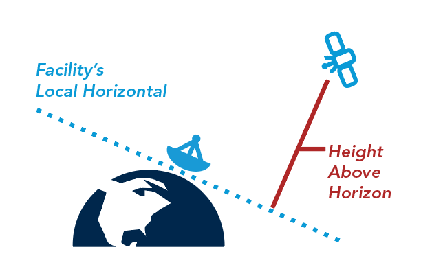
| Height Above Horizon |
If the Height Above Horizon constraint is ON, enter the minimum and/or maximum height of the facility, place, or target above the horizon.
|
F, T, Pl, V |
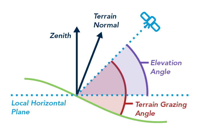
| Terrain Grazing Angle |
If the Terrain Grazing Angle constraint is ON, enter the minimum and/or maximum angle between the relative position vector and the local terrain. This constraint is dependent upon the terrain normal direction specified in the object's Basic properties. If the slope of the terrain is zero, this constraint is equivalent to the Elevation Angle constraint.
|
F, T, Pl, V. P. St |
| Object Exclusion Angle |
Use the Object Exclusion Angle area to select and remove objects that are to be excluded from access computations if they are at the indicated angle from the original object. If the line between the source object and the special body is obstructed (for example, the earth is between a satellite source object and the special body), then the exclusion constraint is not applied. The Object Exclusion Angle constraint is not applied in the determination of access to an excluded object. |
F, T, Pl, V, P, St |
| Elevation Rise-Set |
The Rise-Set Elevation angle constraint allows you to specify different elevation angle limits for the rise-stage and setting-stage of a satellite. For example, a receiver (attached to a sensor and/or a facility) will acquire a rising satellite only when it is 15 degrees above horizon, and will track it down to a 5 degree elevation angle when the satellite is setting. This constraint provides additional flexibility as compared to the normal Elevation angle constraint which applies the same elevation angle limits on the rising and/or setting phase of a satellite. |
F, T, Pl, V, P, St |
| CentralAngle/CentralDistance |
CentralAngle and CentralDistance are constaints for vehicles and ground locations. These constraints provide a simple measure of physical separation using the angle between the position vectors or the angle implied by the maximum radius of the central body. That is the central body of the object owning the constraint. CentralDistance isn't the true distance between projections of the position vectors on the central body's surface. The true distance would account for oblateness of the central body. This constraint does not do that. This constraint can be applied whenever the object involved in the access is not an AreaTarget or LineTarget. |
F, T, Pl, V, P, St |
Assign Objects
Use the following steps to select objects that are to be excluded from access computations if they are at the indicated angle from the original object:
- Turn ON the Use option.
- Use the Exclusion Angle field to indicate the angle from the original object at which an object should be to be excluded from access computations.
- Select the objects to which this constraint should be applied in the Available Objects list.
- Use the Insert button to move objects to which this constraint should be applied from the Available Objects list to the Assigned Objects list.
Remove Objects
Use the following steps to remove objects from the list of Assigned Objects:
- Select the object you wish to remove in the Assigned Objects list.
- Click Remove.