Part 6:
STK Pro, STK Premium (Air), STK Premium (Space), or STK Enterprise
You can obtain the necessary licenses for this tutorial by contacting AGI Support at support@agi.com or 1-800-924-7244.
The results of the tutorial may vary depending on the user settings and data enabled (online operations, terrain server, dynamic Earth data, etc.). It is acceptable to have different results.
This tutorial requires version 12.9 of the STK software or newer.
Capabilities covered
This lesson covers the following capability of the Ansys Systems Tool Kit® (STK®) digital mission engineering software:
- STK Pro
Problem statement
Engineers and operators require an expedient way to determine if local terrain is affecting visibility between ground sites and satellites for purposes such as communications, imaging, and general situational awareness. You are conducting a line-of-sight test between a constellation of GPS satellites, a ground-based test team located in mountainous terrain, a CubeSat communications satellite, and a base team located in Morton, Washington. The effects of the terrain must be taken into account. This test will be used to schedule times for the test team to transmit their location information to the base team, using GPS and a simple FM transmitter and relayed by way of the CubeSat satellite in low Earth orbit.
Solution
Use the STK application to analyze the impact of local terrain on accesses between the GPS constellation, the test team, a CubeSat satellite, and the base team. First, load a USGS Digital Elevation Model (DEM) file and convert it to a STK terrain inlay (.pdtt) file, which can be used to visualize terrain in the 3D Graphics window. Then, create a constellation of GPS satellites, use Place objects as the teams' locations, and insert a Satellite object for the CubeSat. Factor in the impact of local terrain using terrain and azimuth-elevation (AzEl) masks. Finally, model the communications links with a Chain object to create connections between all the nodes.
What you will learn
Upon completion of this tutorial, you will be able to:
- Create an STK terrain inlay file from a local terrain file
- Use local terrain files for analysis
- Model a Constellation object
- Model a Chain object
Video guidance
Watch the following video. Then follow the steps below, which incorporate the systems and missions you work on (sample inputs provided).
Creating a new scenario
Create a new scenario using the default 24-hour analysis period.
- Launch the STK application (
 ).
). - Click
 Create a Scenario in the Welcome to STK dialog box.
 - Enter the following in the STK: New Scenario Wizard:
- Click when you finish.
- Click Save (
 ) when the scenario loads. A folder with the same name as your scenario is created for you.
 - Verify the scenario name and location in the Save As dialog box.
- Click .
| Option | Value |
|---|---|
| Name | TerrainChainsConstellations |
| Start | Default |
| Stop | Default |
Save (![]() ) often!
) often!
Locating the U.S. Geological Survey DEM file
Find and copy the preinstalled
The DEM file used in this tutorial is located inside a compressed (zipped) file in the install directory. Take a moment to copy the file out of the zipped file archive. Do not extract the entire archive. Follow the instructions in the tutorial to use the file.
- Using Windows File Explorer, browse to the location of the DEM file in the install directory:
- STK 12: C:\Program Files\AGI\STK 12\CodeSamples\CodeSamples.zip\SharedResources\Scenarios\Events
- STK 13: C:\Program Files\AGI\STK_ODTK 13\CodeSamples\STKCodeSamples.zip\SharedResources\Scenarios\Events
- Copy the file named hoquiam-e.dem.
- Navigate to your scenario folder.
- Paste the hoquiam-e.dem file into your scenario folder.
- Close Windows File Explorer.
Using the DEM file for analysis
The STK application provides a foundation for analyzing and visualizing complex systems in the context of their missions. You'll use the DEM terrain data file you copied out of the zipped Code Samples file for both analytical and visual terrain in your scenario. The file contains digital elevation data for Mount St. Helens and the vicinity near the city of Hoquiam, Washington.
Turning off streaming terrain
By turning off
- Right-click on TerrainChainsContellations () in the Object Browser.
- Select Properties (
 ) in the shortcut menu.
 - Select the Basic - Terrain page when the Properties Browser opens.
- Clear the Use terrain server for analysis check box in the Terrain Server panel.
- Click to confirm your change and to keep the Properties Browser open.
Loading the local DEM file
Now, load the hoquiam-e.dem terrain data file on your local machine into the scenario for analysis.
- Click in the Custom Analysis Terrain Sources panel.
- Open the file type drop-down list when the Open dialog box opens.
- Select USGS DEM (DEM).
- Browse to your scenario folder
- Select hoquiam-e.dem.
- Click to select the file and to close the Open dialog box.
- Click to confirm your selection and to close the Properties Browser.
Creating a terrain inlay using the Imagery and Terrain Converter
Use the
Selecting the DEM file for conversion
Select the DEM file as the source of the terrain data.
- Select the Utilities menu in the menu bar.
- Select Imagery and Terrain Converter... in the Utilities menu.
- Select the Terrain Region page when the Imagery and Terrain Converter opens.
- Open the Terrain Source drop-down list in the Input Data panel.
- Select the path to the hoquiam-e.dem file.
Setting the terrain output data
Specify the file location and the filename of the terrain file you will create.
- Click the Directory ellipsis (
 ) in the Output Data panel.
 - Navigate to the location of your scenario (e.g. C:\Users\<username>\Documents\STK_ODTK 13\TerrainChainsConstellations when the Directory dialog box opens.
- Click to confirm your selection and to close the Directory dialog box.
- Enter StHelensTerrain in the Filename field in the Output Data panel.
- Click .
- Click to close the Imagery and Terrain Converter when finished.
Adding the terrain inlay with Globe Manager
The Globe Manager allows you to customize scenario globes with imagery and terrain data and to manage that data once it has been applied.
Opening Globe Manager
Open Globe Manager from the Globe Manager Toolbar in the 3D Graphics window.
- Bring the 3D Graphics window to the front.
- Click Globe Manager (
 ) in the Globe Manager toolbar.
Selecting the files to display in the 3D Graphics window
You can use Globe Manage to select imagery and terrain data for display in the 3D Graphics window.
- Click Add Terrain/Imagery (
 ) In the Hierarchy toolbar when Globe Manager opens.
 - Select Add Terrain/Imagery... (
 ) in the drop-down menu.
 - Open the Path drop-down list when the Globe Manager: Open Terrain and Imagery Data dialog box opens.
- Select the path to your scenario (e.g. C:\Users\<username>\Documents\STK_ODTK 13\TerrainChainsConstellations).
- Select the check box for StHelensTerrain.pdtt.
- Click .
- Click when the Use Terrain for Analysis dialog box opens.
The Hierarchy tab is used to add central bodies, image, and terrain items to a scenario.
You're already using the hoquiam-e.dem file for analysis.
Viewing the terrain inlay in the 3D Graphics window
Gain situational awareness by viewing the terrain inlay in the 3D Graphics window.
- Bring the 3D Graphics window to the front.
- Right-click on StHelensTerrain.pdtt (
 ) in the Globe Manager hierarchy.
 - Select Zoom To (
 ) in the shortcut menu.
 - Use your mouse to view the image and surrounding terrain.
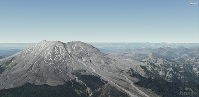
Mount St. Helens Terrain
Inserting operational GPS satellites
Add the constellation of currently operational GPS satellites into your scenario.
Using the Standard Object Database
Use the
- Return to the STK application.
- Bring the Insert STK Objects tool (
 ) to the front.
 - Select Satellite (
 ) in the Select An Object To Be Inserted list.
 - Select From Standard Object Database (
 ) in the Select A Method list.
 - Click .
Selecting operational GPS satellites
Search for operational GPS satellites using the online AGI Standard Object Data Service.
- Clear the Data Sources - Local check box.
- Enter GPS in the Name or ID field.
- Select Operational in the Operational Status drop-down list.
- Click .
- Select the Create Constellation from Selected check box in the Insert Options panel.
- Enter GPS_Sats in the Name field in the Insert Options panel.
- Select all the satellites in the Results list.
- Click .
- When all the GPS satellites have propagated, click to close the Search Standard Object Data dialog box.
You can also insert the GPS satellites one at a time, if you find that to be easier. You'll have to make sure you click in the dialog box that opens after clicking to make sure you add all the GPS satellites to the existing GPS_Sats constellation.
Viewing the GPS satellites assigned to the constellation
Open the Constellation object's
- Open GPS_Sats' (
 ) Properties ().
 - Select the Basic - Definition page when the Properties Browser opens.
You can see that the GPS Satellite (![]() ) objects are placed in the Assigned Objects list.
) objects are placed in the Assigned Objects list.
Updating the GPS constellation's constraints
- Select the Constraints - Basic page.
- Open the From access position drop-down list in the Logical Restriction panel.
- Select At Least N.
- Enter 4 in the At Least N field.
- Click to confirm your changes and to close the Properties Browser.
Although you aren't analyzing dilution of precision or navigation accuracy, you are testing the link for proper accesses. Therefore, you want to make sure that the test team can access at least four GPS satellites at all times. Anything less than four will not be considered a successful access.
Cleaning ground tracks and orbits from the 2D and 3D Graphics windows
You will override the default display of satellite ground tracks and orbits. You have multiple satellites propagated into your scenario. By clearing these two check boxes, your 2D and 3D Graphics windows will be easier to use for situational awareness.
- Bring the 3D Graphics window to the front.
- Zoom out until you can see all the GPS orbits and ground tracks on the surface of the Earth.
- Open TerrainChainsContellations () Properties ().
- Select the 2D Graphics - Global Attributes page when the Properties Browser opens.
- Clear the Show Ground Tracks / Routes check box in the Vehicles panel.
- Clear the Show Orbits / Trajectories check box.
- Click to confirm your changes and to close the Properties Browser.
Inserting the test team's location
Insert a Place object, which will simulate the location of the test team.
- Bring the Insert STK Objects tool () to the front.
- Insert a Place (
 ) object using the Insert Default () method.
 - Right-click on Place1 () in the Object Browser.
- Select Rename in the shortcut menu.
- Rename Place1 () TestTeam.
Updating the test team's position
The test team is located in very mountainous terrain. Update TestTeam's
- Open TestTeam's () Properties ().
- Select the Basic - Position page when the Properties Browser opens.
- Set the following options in the Position panel:
- Click to confirm your changes and to keep the Properties Browser open.
| Option | Value |
|---|---|
| Latitude | 46.304 deg |
| Longitude | -122.321 deg |
| Height Above Ground | 6 ft |
Height Above Ground represents the height of Test Team's antenna if you were analyzing communication devices.
Using a terrain mask constraint
Use the
- Select the Constraints - Active page.
- Click Add new constraints (
 ) in the Active Constraints toolbar.
 - Select Terrain Mask in the Constraint Name list when the Select Constraints to Add dialog box opens.
- Click .
- Click to close the Select Constraints to Add dialog box.
- Click to confirm your selection and to close the Properties Browser.
Inserting the base team's location
The base team is located in the city of Morton, Washington.
- Bring the Insert STK Objects tool () to the front.
- Insert a Place () object using the From City Database () method.
- Enter Morton in the Name field when the Search Standard Object Data dialog box opens.
- Click .
- Select Morton - Washington in the Results list.
- Click .
- Click to close the Search Standard Object Data dialog box.
Raising the base team's height above the ground
Although you aren't using an actual antenna in your analysis, the location of the antenna on the base team's building is located on the building's roof, which is 25 feet above ground level.
- Open Morton's () Properties ().
- Select the Basic - Position page when the Properties Browser opens.
- Enter 25 ft in the Height Above Ground field in the Position panel.
- Click to confirm your change and to keep the Properties Browser open.
Using an azimuth-elevation mask in your analysis
Using the azimuth-elevation (AzEl) mask is another way of using analytical terrain in your analysis. The AzElMask properties, which are a part of the Basic properties for facilities, places and targets, enable you to
You can construct terrain-based AzEl masks by extending a number of rays in directions of constant azimuth outwards from the facility, place, or target location. Obstruction information is stored along each ray. During visibility computations, the STK software uses obstruction information from the two rays that bound the current direction of interest to compute an interpolated visibility metric.
Defining Morton's AzEl mask
Define an AzEl mask for Morton through its Properties.
- Select the Basic - AzElMask page.
- Set the following options:
- Click to confirm your changes and to keep the Properties Browser open.
| Option | Value |
|---|---|
| Use | Terrain Data |
| Max range to consider | 160 km |
| Use Mask for Access Constraint | Selected |
Using Terrain Data automatically creates and stores an AzEl mask file, which is an ASCII text file that is formatted for compatibility with the STK software and ends in an .aem extension, into your scenario folder. Selecting Use Mask for Access Constraint enables the AzEl Mask constraint located on the Constraints - Active page. Using the AzElMask constraint constrains access to a 360-degree field of view around the object being constrained.
Displaying Morton's AzEl mask
For situational awareness, you can display the AzEl mask in both the 2D Graphics and 3D Graphics windows at a specified number of steps from the minimum to the maximum range from Morton's antenna.
- Select the 2D Graphics - AzElMask page.
- Set the following properties in the At Range panel:
- Click to confirm your changes and to close the Properties Browser.
| Option | Value |
|---|---|
| Show | Selected |
| Number of Steps | 16 |
| Minimum Range | 0 km |
| Maximum Range | 160 km |
Decluttering the 3D Graphics window
Although it's not required, you can adjust the properties of the 3D Graphics window to have better situational awareness. Objects located on the surface of the terrain could be covered by the terrain, which makes them unreadable. You can fix this by making a change to the 3D Graphics window's properties.
- Bring the 3D Graphics window to the front.
- Click Properties () on the 3D Window Defaults toolbar.
- Select the Details page when the Properties Browser opens.
- Select the Enable check box in the Label Declutter panel.
- Click to confirm your selection and to close the Properties Browser.
Viewing the AzEl mask in the 3D Graphics window
View the AzEl mask in context in the 3D Graphics window.
- Bring the 3D Graphics window to the front.
- Right-click on Morton () in the Object Browser.
- Select Zoom To in the shortcut menu.
- Using your mouse, zoom out until you can see the visual representation of the AzEl mask.
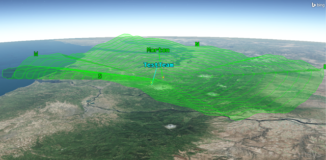
Morton's Azimuth-Elevation Mask
Adding a CubeSat communications satellite
When looking at the AzEl mask in the 3D Graphics window, it's clear that the base team cannot access test team directly through line-of-sight communication. In order for the test team to access the base team, a CubeSat communications satellite, which is located in a low Earth orbit (LEO), is needed.
Inserting a Satellite object
Insert a Satellite object to model the CubeSat satellite.
- Bring the Insert STK Objects tool () to the front.
- Insert a Satellite () object using the Insert Default () method.
- Rename Satellite1 () CubeSat.
Propagating the CubeSat satellite
You can set the orbital parameters of the CubeSat satellite by updating the CubeSat's Satellite object's properties.
- Open CubeSat's () Properties ().
- Select the Basic - Orbit page when the Properties Browser opens.
- Enter the following orbital parameters:
- Click to propagate CubeSat () and to close the Properties Browser.
| Option | Value |
|---|---|
| Semimajor Axis | 6997 km |
| Eccentricity | 0.02 |
| Inclination | 64.8 deg |
| Argument of Perigee | 267 deg |
| RAAN | 2 deg |
| True Anomaly | 302 deg |
Building a Chain object
You are now ready to test access starting from the GPS satellite constellation and ending at Morton. You need a
Inserting the Chain object
Assign objects to the chain and define the order in which objects are accessed.
- Bring the Insert STK Objects tool () to the front.
- Insert a Chain (
 ) object using the Insert Default () method.
 - Rename Chain1 () GPS_to_Morton.
Defining the start and end objects
Start by choosing the start object and end object in your chain.
- Open GPS_to_Morton's () Properties ().
- Select the Basic - Definition page when the Properties Browser opens.
- Click the Start Object ellipsis ().
- Select GPS_Sats () when the Select Object dialog box opens.
- Click to close the Select Object dialog box.
- Click the End Object ellipsis ().
- Select Morton () when the Select Object dialog box opens.
- Click to close the Select Object dialog box.
Creating the Chain object's first connection
After you choose the start and end objects in your chain, you need to build the chain's connections. It doesn't matter in which order you place the connections in the Connections list. What matters is the From Object must be able to access the To Object.
- Click in the Connections panel.
- Click the From Object ellipsis ().
- Select GPS_Sats () when the Select Object dialog box opens.
- Click to close the Select Object dialog box.
- Click the To Object ellipsis ().
- Select TestTeam () when the Select Object dialog box opens.
- Click to close the Select Object dialog box.
Creating the Chain object's second connection
When the test team accesses at least four GPS satellites, they will uplink their fix to the CubeSat satellite.
- Click in the Connections panel.
- Click the To Object ellipsis ().
- Select CubeSat () when the Select Object dialog box opens.
- Click to close the Select Object dialog box.
Creating the Chain object's final connection
The CubeSat satellite will downlink test team's fix to the base team located in Morton.
- Click in the Connections panel.
- Click the To Object ellipsis ().
- Select Morton () when the Select Object dialog box opens.
- Click to close the Select Object dialog box.
- Click to confirm your changes and to close the Properties Browser.
Computing Chain accesses
You are ready to compute the Chain object's accesses.
- Select GPS_to_Morton () in the Object Browser.
- Select the Chain menu.
- Select Compute Accesses.
Generating a Complete Chain Access report
Generate a
- Right-click on GPS_to_Morton () in the Object Browser.
- Select Report & Graph Manager... (
 ) in the shortcut menu.
 - Select the Complete Chain Access (
 ) report in the Installed Styles folder (
 ) in the Styles panel when the Report & Graph Manager opens.
 - Click .
You could use this report to view the windows of opportunity you'll have to transmit the test team's location to the base team in Morton.
Viewing the accesses in the 3D Graphics window
You can view a complete chain access in the 3D Graphics window directly from the Complete Chain Access report.
- Right-click on the Start Time of the longest access duration.
- Select Start Time in the shortcut menu.
- Select Set Animation Time in the Start Time submenu.
- Bring the 3D Graphics window to the front.
- Zoom to Morton ().
- Using your mouse, maneuver your view to get an idea of all the connections in your chain.
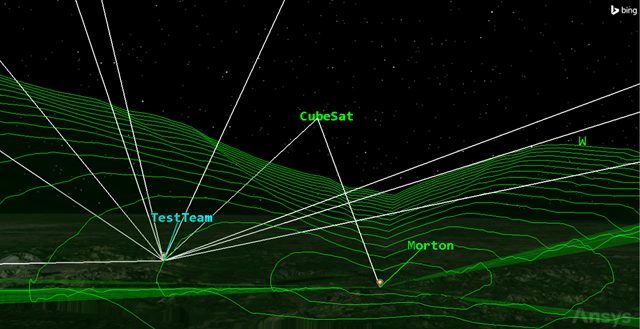
Complete chain access
Saving your work
Clean up and close out your scenario.
- Close any open reports, properties, and the Report & Graph Manager.
- Save () your work.
Summary
You conducted a line-of-sight test between a constellation of GPS satellites, a ground-based test team located in mountainous terrain, a CubeSat and a base team located in Morton, Washington. You loaded a USGS DEM file to analyze the impact of local terrain on accesses between the GPS constellation, the test team, the CubeSat and the base team. Using the Terrain Region Converter, you changed the DEM file into a terrain inlay file and used that to visualize the terrain in the 3D Graphics window and to create an azimuth-elevation mask. Next, you created a constellation of GPS satellites, used Place objects to represent the teams' locations, and used a Chain object to create connections between all the objects. Finally, you visualized the complete chain access linking the components together and generated a Complete Chain Access report, which could be used for further mission planning.