STK Pro, STK Premium (Air), STK Premium (Space), or STK Enterprise
You can obtain the necessary licenses for this tutorial by contacting AGI Support at support@agi.com or 1-800-924-7244.
The results of the tutorial may vary depending on the user settings and data enabled (online operations, terrain server, dynamic Earth data, etc.). It is acceptable to have different results.
Capabilities covered
This lesson covers the following capability of the Ansys Systems Tool Kit® (STK®) digital mission engineering software:
- STK Pro
Problem statement
Engineers and analysts require a way to design, test, and analyze satellite orbits. They need to simulate multiple orbits of different types quickly and efficiently.
Solution
Use the Orbit Wizard to design nine (9) standard orbits. You will model two kinds of satellite orbits: satellite orbits used to view the Earth's surface and satellite orbits used to communicate with a ground site.
What you will learn
Upon completion of this tutorial, you will understand the following:
- The Orbit Wizard
- Orbit Wizard orbit types
Creating a new scenario
First, you must create a new scenario, then build from there.
- Launch the STK (
 ) application.
 - Click
 Create a Scenario in the Welcome to STK dialog box.
 - Enter the following in the New Scenario Wizard:
- Click when you finish.
- Click Save (
 ) when the scenario loads.
 - Verify the scenario name and location when the Save As dialog box opens.
- Click .
| Option | Value |
|---|---|
| Name | OrbitWizard |
| Location | Default |
| Start | Default |
| Stop | + 2 days |
The STK application automatically creates a folder with the same name as your scenario for you.
Modeling the ground site
The basis for your comparison is a ground site, for which you will determine access times to your Sensor objects.
Inserting a Facility object
Insert a
- Bring the Insert STK Objects (
 ) tool to the front.
 - Select Facility (
 ) in the Select An Object to Be Inserted list.
 - Select Define Properties (
 ) in the Select A Method list.
 - Click .
Selecting the location of the Facility object
Place the Facility object near the geographic center of the contiguous United States.
- Select the Basic - Position page when the Properties Browser opens.
- Enter the following coordinates in the Position panel:
- Click to confirm your changes and to close the Properties Browser.
- Right-click on Facility1 () in the Object Browser.
- Select Rename in the shortcut menu.
- Rename Facility1 () US_Center.
| Option | Value |
|---|---|
| Latitude | 39.8281 deg |
| Longitude | -98.5795 deg |
Using the Orbit Wizard
The Orbit Wizard is a satellite-level tool designed to assist you in either creating any one of several standard orbits or designing your own satellite orbit. The configurable options available depends on the orbit type selected.
Inserting a Satellite object
Insert a Satellite object using the Orbit Wizard method.
- Bring the Insert STK Objects tool () to the front.
- Insert a Satellite (
 ) object using the Orbit Wizard (
 ) method.
Using the Circular orbit type
You will start with a Circular orbit type. Circular orbits have a constant radius. Place this satellite in a medium Earth orbit (MEO) that's similar to that of a GPS satellite.
- Leave the default Type set to Circular when the Orbit Wizard opens.
- Enter MEO_Circ_Sat in the Satellite Name field.
- Enter the following values in the Definition panel.
- Click to propagate MEO_Circ_Sat () and to close the Orbit Wizard.
| Option | Value |
|---|---|
| Inclination | 54.8 deg |
| Altitude | 20000 km |
| RAAN | 336 deg |
If you ever need to adjust an orbit your created with the Orbit Wizard, you can select a Satellite object in the Object Browser, then select Orbit Wizard... in the Satellite menu on the Menu Bar to reopen the Orbit Wizard for that satellite.
Inserting a Sensor object
MEO_Circ_Sat in this scenario will be used for low-gain communications. In this instance, you want to use a
- Insert a Sensor (
 ) object using the Define Properties () method.
 - Select MEO_Circ_Sat () in the Select Object dialog box.
- Click to confirm your selection and to close the Select Object dialog box.
- Select the Basic - Definition page when the Properties Browser opens.
- Enter 14 deg in the Cone Half Angle field in the Simple Conic panel.
- Click to confirm your changes and to close the Properties Browser.
- Rename Sensor1 () MEO_Circ_Sens.
At this altitude, the full cone angle of 28 degrees will provide good visualization of your expected communication reception on the ground.
Viewing the Circular orbit
View the Circular orbit in the 2D and 3D Graphics windows.
- Click on the 2D Graphics window.
- Select the Window menu on the Menu Bar.
- Select Tile Vertically in the Window menu.
- Use your mouse to obtain a good view of the Circular orbit type in both windows.
- Clear MEO_Circ_Sat's () check box in the Object Browser.
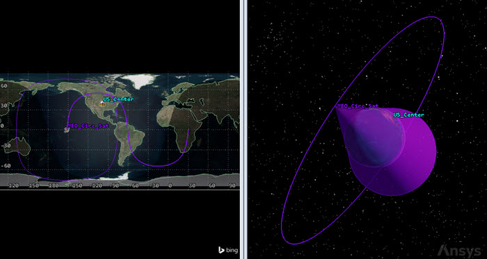
circular orbit
Using the Critically Inclined orbit type
Critically inclined orbits maintain perigee at a fixed latitude. Their lines of apsides do not change over time. This satellite will be used view the surface of the Earth.
- Bring the Insert STK Objects tool () to the front.
- Insert a Satellite () object using the Orbit Wizard () method.
- Open the Type drop-down list when the Orbit Wizard opens.
- Select Critically Inclined.
- Enter Crit_Inclined_Sat in the Satellite Name field.
- Use the default values.
- Click to propagate Crit_Inclined_Sat () and to close the Orbit Wizard.
Inserting a Sensor object
You will use a Rectangular sensor type. Rectangular sensor types are typically used with satellites or aircraft for modeling the field of view of instruments such as pushbroom sensors and star trackers. Rectangular sensors are defined according to specified vertical and horizontal half-angles.
- Bring the Insert STK Objects tool () to the front.
- Insert a Sensor () object using the Define Properties () method.
- Select Crit_Inclined_Sat () in the Select Object dialog box.
- Click to confirm your selection and to close the Select Object dialog box.
- Select the Basic - Definition page when the Properties Browser opens.
- Open the Sensor Type drop-down list.
- Select Rectangular.
- Enter the following values in the Rectangular panel:
- Click to confirm your changes and to close the Properties Browser.
- Rename Sensor2 () Crit_Inclined_Sens.
| Option | Value |
|---|---|
| Vertical Half Angle | 15 deg |
| Horizontal Half Angle | 5 deg |
Viewing the Critically Inclined orbit
View the Critically Inclined orbit in the 2D and 3D Graphics windows.
- Use your mouse to obtain a good view of the Critically Inclined orbit in both windows.
- Clear Crit_Inclined_Sat's () check box in the Object Browser.
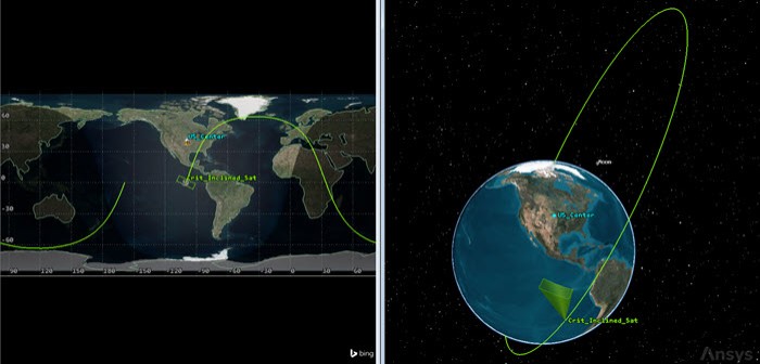
Critically Inclined orbit
Using the Critically Inclined, Sun Sync orbit type
Critically inclined, Sun-synchronous orbits combine the features of both basic types of orbits. The orbit uses a retrograde inclination of 116.565 degrees. A satellite in a critically inclined, Sun-synchronous orbit will pass overhead at the same local mean solar time for each revolution and it has a perigee, which remains at a fixed latitude. This satellite will be used view the surface of the Earth.
- Bring the Insert STK Objects tool () to the front.
- Insert a Satellite () object using the Orbit Wizard () method.
- Open the Type drop-down list when the Orbit Wizard opens.
- Select Critically Inclined, Sun Sync.
- Enter Crit_Inclined_SunSync_Sat in the Satellite Name field.
- Enter -80 deg in the Longitude of Ascending Node field in the Position panel.
- Click to propagate Crit_Inclined_SunSync_Sat () and to close the Orbit Wizard.
Reusing Sensor objects
To save time, all of your satellites viewing the surface of the Earth will use Crit_Inclined_Sens. You can simply copy and paste this sensor to other satellites performing the same type of mission.
- Select Crit_Inclined_Sens () in the Object Browser.
- Click Copy (
 ) on the Object Browser toolbar.
 - Select Crit_Inclined_SunSync_Sat () in the Object Browser.
- Click Paste (
 ) on the Object Browser toolbar.
 - Rename Crit_Inclined_Sens1 () Crit_Inclined_SunSync_Sens.
Viewing the Critically Inclined, Sun Sync orbit
View the Critically Inclined, Sun Sync orbit in the 2D and 3D Graphics windows.
- Use your mouse to obtain a good view of the Critically Inclined, Sun Sync orbit in both windows.
- Clear Crit_Inclined_SunSync_Sat's () check box in the Object Browser.

Critically Inclined, sun sync orbit
Using the Geosynchronous orbit type
A satellite in a geosynchronous orbit will remain fixed in the sky above the specified fixed longitude. This satellite will be used for communications.
- Bring the Insert STK Objects tool () to the front.
- Insert a Satellite () object using the Orbit Wizard () method.
- Open the Type drop-down list when the Orbit Wizard opens.
- Select Geosynchronous.
- Enter GEO_Sat in the Satellite Name field.
- Enter -120 deg in the Subsatellite Point field in the Definition panel.
- Enter 2 deg in the Inclination field.
- Click to propagate GEO_Sat () and to close the Orbit Wizard.
Inserting a Sensor object
Since GEO_Sat in this scenario will be used for Ku-band communications, use a Half Power sensor type to simulate the approximate field of view of a parabolic antenna.
- Bring the Insert STK Objects tool () to the front.
- Insert a Sensor () object using the Define Properties () method.
- Select GEO_Sat () in the Select Object dialog box.
- Click to confirm your selection and to close the Select Object dialog box.
- Select the Basic - Definition page when the Properties Browser opens.
- Open the Sensor Type drop-down list.
- Select Half Power.
- Use the default values in the Half Power panel.
- Click to confirm your selection and to keep the Properties Browser open.
Pointing the sensor's boresite
Point the Sensor object's boresite in a fixed direction in the vicinity of US_Center by updating its
- Select the Basic - Pointing page.
- Set the following values in the Fixed panel:
- Click to confirm your changes and to close the Properties Browser.
- Rename Sensor3 () GEO_Sens.
| Option | Value |
|---|---|
| Azimuth | -66.1 deg |
| Elevation | 83.3 deg |
Viewing the Geosynchronous orbit
View the Geosynchronous orbit in the 2D and 3D Graphics windows.
- Use your mouse to obtain a good view of the Geosynchronous orbit in both windows.
- Clear GEO_Sat's () check box in the Object Browser.
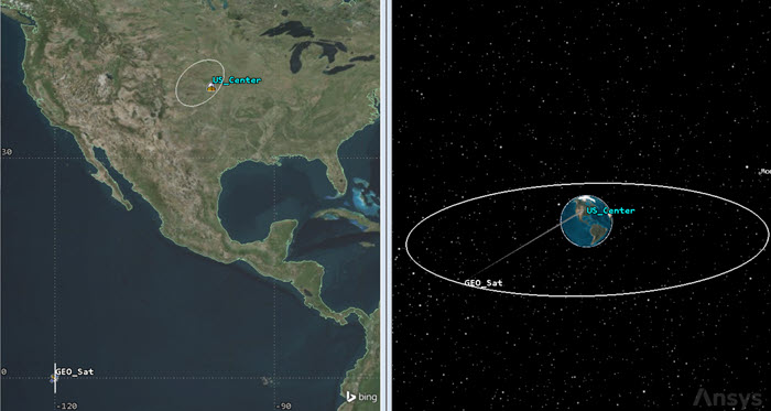
Geosynchronous orbit
Using the Molniya orbit type
Molniya orbits are highly eccentric, meaning that there is a large difference between the altitude at apogee and the altitude of perigee. Molniya orbits are also critically inclined. This keeps the perigee of the orbit in the Southern Hemisphere. Molniya orbits also have a long dwell time in the extreme latitude regions of the Northern Hemisphere. This satellite will be used for communications.
- Bring the Insert STK Objects tool () to the front.
- Insert a Satellite () object using the Orbit Wizard () method.
- Open the Type drop-down list when the Orbit Wizard opens.
- Select Molniya.
- Enter Molniya_Sat in the Satellite Name field.
- Click to propagate Molniya_Sat () and to close the Orbit Wizard.
- Copy and paste MEO_Circ_Sens () to Molniya_Sat ().
- Rename MEO_Circ_Sens1 () Molniya_Sens.
Viewing the Molniya orbit
View the Molniya orbit in the 2D and 3D Graphics windows.
- Use your mouse to obtain a good view of the Molniya orbit in both windows.
- Clear Molniya_Sat's () check box in the Object Browser.
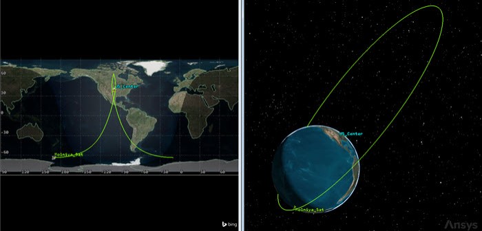
Molniya orbit
Using the Orbit Designer orbit type to create a Tundra orbit
With this option, you can create any orbit you wish. Use the Orbit Designer to create a Tundra orbit, which has a an apogee dwell. This orbit is well-suited for communication satellites in high-latitude regions.
- Bring the Insert STK Objects tool () to the front.
- Insert a Satellite () object using the Orbit Wizard () method.
- Open the Type drop-down list when the Orbit Wizard opens.
- Select Orbit Designer.
- Enter Designer_Sat in the Satellite Name field.
- Enter the following parameters in the Orbital Elements panel:
- Click to propagate Designer_Sat () and to close the Orbit Wizard.
- Copy and paste MEO_Circ_Sens () to Designer_Sat ().
- Rename MEO_Circ_Sens1 () Designer_Sens.
| Option | Value |
|---|---|
| Semimajor Axis | 42164 km |
| Eccentricity | 0.2 |
| Inclination | 63.4 deg |
| Argument of Perigee | 270 deg |
| RAAN | 119 deg |
| True Anomaly | 0 deg |
Viewing the Tundra orbit
View the Orbit Designer orbit in the 2D and 3D Graphics windows.
- Use your mouse to obtain a good view of the Orbit Designer orbit in both windows.
- Clear Designer_Sat's () check box in the Object Browser.
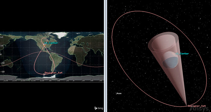
tundra orbit From Orbit Designer
Using the Repeating Ground Trace orbit type
Orbits with a repeating ground trace are useful when identical viewing conditions are desired at different times to detect changes. The ground trace may be caused to repeat every day or to interweave from day to day before repeating. This satellite will be used view the surface of the Earth.
- Bring the Insert STK Objects tool () to the front.
- Insert a Satellite () object using the Orbit Wizard () method.
- Open the Type drop-down list when the Orbit Wizard opens.
- Select Repeating Ground Trace.
- Enter Repeat_Sat in the Satellite Name field.
- Enter -88 deg in the Longitude of First Ascending Node field in the Definition panel.
- Click to propagate Repeat_Sat () and to close the Orbit Wizard.
- Copy and paste Crit_Inclined_Sens () to Repeat_Sat ().
- Rename Crit_Inclined_Sens1 () Repeat_Sens.
Viewing the Repeating Ground Trace orbit
View the Repeating Ground Trace orbit in the 2D and 3D Graphics windows.
- Use your mouse to obtain a good view of the Repeating Ground Trace orbit in both windows.
- Clear Repeat_Sat's () check box in the Object Browser.
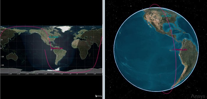
Repeating Ground Trace orbit
Using the Repeating Sun Sync orbit type
Sun-synchronous orbits with a repeating ground trace are useful when identical viewing and lighting conditions are desired at different times to detect changes. The ground trace may be caused to repeat every day or to interweave from day to day before repeating. The orbit repeats the ground coverage cycle and passes overhead at approximately the same local mean solar time for each revolution. This satellite will be used view the surface of the Earth.
- Bring the Insert STK Objects tool () to the front.
- Insert a Satellite () object using the Orbit Wizard () method.
- Open the Type drop-down list when the Orbit Wizard opens.
- Select Repeating Sun Sync.
- Enter Repeat_Sun_Sat in the Satellite Name field.
- Enter 13 deg in the Lon. of First Ascending Node field in the Definition panel.
- Click to propagate Repeat_Sun_Sat () and to close the Orbit Wizard.
- Copy and paste Crit_Inclined_Sens () to Repeat_Sun_Sat ().
- Rename Crit_Inclined_Sens1 () Repeat_Sun_Sens.
Viewing the Repeating Sun Sync orbit
View the Repeating Sun Sync orbit in the 2D and 3D Graphics windows.
- Use your mouse to obtain a good view of the Repeating Sun Sync orbit in both windows.
- Clear Repeat_Sun_Sat's () check box in the Object Browser.
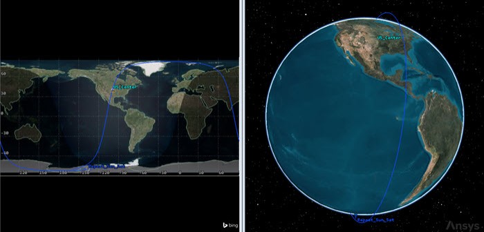
Repeating Sun Sync orbit
Using the Sun Synchronous orbit type
Sun-synchronous orbits are designed to utilize the effect of the Earth's oblateness, causing the orbit plane to precess at a rate equal to the mean orbital rate of the Earth around the Sun. Sun-synchronous orbits have the property that their nodes maintain constant local mean solar times. This satellite will be used view the surface of the Earth.
- Bring the Insert STK Objects tool () to the front.
- Insert a Satellite () object using the Orbit Wizard () method.
- Open the Type drop-down list when the Orbit Wizard opens.
- Select Sun Synchronous.
- Enter Sun_Sync_Sat in the Satellite Name field.
- Enter 11:44:00.000 HMS in the Local Time of Descending Node field in the Node Definition panel.
- Click to propagate Sun_Sync_Sat () and to close the Orbit Wizard.
- Copy and paste Crit_Inclined_Sens () to Sun_Sync_Sat ().
- Rename Crit_Inclined_Sens1 () Sun_Sync_Sens.
Viewing the Sun Synchronous orbit
View the Sun Synchronous orbit in the 2D and 3D Graphics windows.
- Use your mouse to obtain a good view of the Sun Synchronous orbit in both windows.
- Save () your scenario.
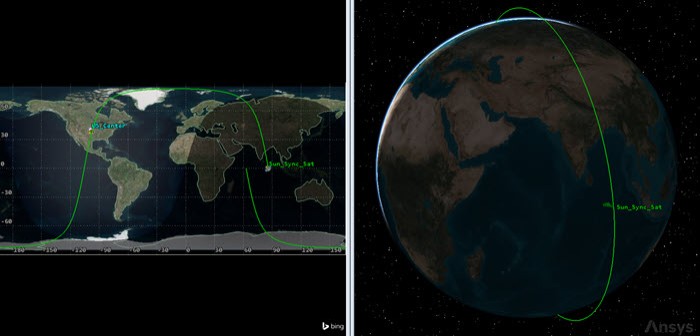
Sun Synchronous orbit
Viewing all nine orbits simultaneously
It's interesting to compare all nine (9) orbit types simultaneously in the 3D Graphics window.
- Using the Ctrl key and left mouse button to multi-select all the Satellite () objects in the Object Browser.
- Click on one of the Satellite () object check boxes to make them all visual in the 2D and 3D Graphics windows.
- Click Properties () on the Object Browser toolbar.
- Select the 3D Graphics - Model page when the Properties Browser opens.
- Move the Details - Maximum Viewing Distance - All slider all the way to the right in the Detail Thresholds panel.
- Click to confirm your changes and to close the Properties Browser.
- Bring the 3D Graphics window to the front.
- Zoom out so that you can see all nine (9) orbits.
- Click Start (
 ) on the Animation toolbar to animate the scenario.
 - Click Reset (
 ) when finished.
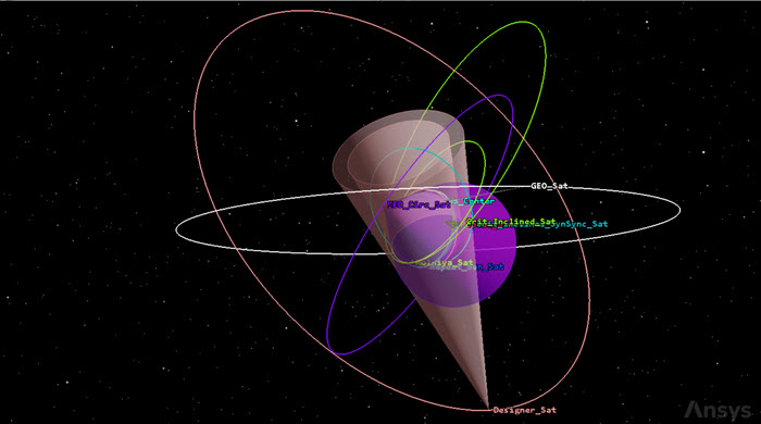
viewing all orbit types
Using the Access tool
You can analyze access times for all Sensor objects simultaneously to determine which orbit type accesses US_Center the longest by using the
- Right-click on US_Center () in the Object Browser.
- Select Access... (
 ) in the shortcut menu.
 - Expand (
 ) Crit_Inclined_Sat () in the Associated Objects list when the Access tool opens.
 - Right-click on Crit_Inclined_Sens ().
- Select Select All Sensors in the shortcut menu.
- Click
 .
. - Click in the Reports panel.
Viewing the access data
You can use the Access report to determine which orbit type will access US_Center the longest and shortest amount of time, and if any of your Satellite objects don't have any accesses.
- Scroll through the Access report.
- Answer some questions based on the access report:
- Which orbit type has the longest Total Duration access time?
- Which orbit type has the shortest Total Duration access time?
- Do you have any orbit types with No Access Found?
- Close the Access report when finished.
Generating an Access graph
When viewing multiple accesses using different orbit types, an
- Click in the Graphs panel.
- Close the Access graph and the Access tool when you are finished.
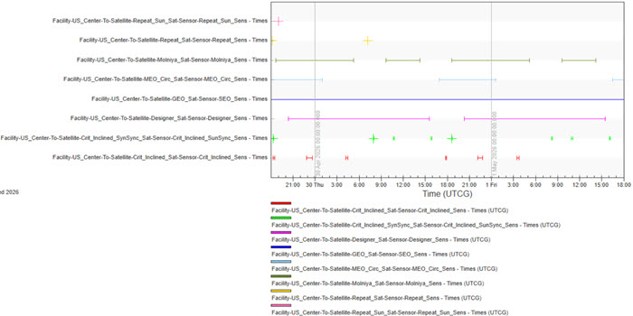
access graph
Saving your work
Clean up your workspace and close out your scenario.
- Close out any open reports and tools that are still open.
- Save () your work.
- Close the scenario when you are finished.
Summary
This scenario was designed to provide an overall understanding of the Orbit Wizard and the orbit types that are provided for your use. All of the Earth-observing satellites used rectangular sensor types. All the communication satellites (expect the geosynchronous satellite) used sensor objects viewing from horizon to horizon. The geosynchronous satellite instead used a half power sensor type, which focused its view in the vicinity of the ground site. Using the Access tool, you created an Access report to determine with Sensor object accessed the ground site the longest during the two-day analysis period. Finally, you created an Access graph, which provided a snapshot of all the accesses at one time.
On your own
You mostly used the default values for your satellite orbits. Some of your sensors had low to no access durations. Change some of the orbital parameters and see if you can increase access times for those satellites.