Solid Primitive
The solid primitive,
SolidPrimitive, is used to visualize solids, such as boxes,
ellipsoids, and cylinders, computed using a triangulator. The solid
primitive can display the interior fill, the outline with various
appearances, and the silhouette.
Box Triangulator
The box triangulator,
BoxTriangulator, computes a
SolidTriangulatorResult for a box centered at the origin. This
result can be provided to a solid primitive's
SetWithResult method to visualize the interior fill and outline
of the box. Since the box is centered at the origin and axis
aligned, it should be positioned and orientated using the
primitive's
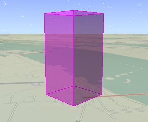
ReferenceFrame. The following example uses a solid primitive to
visualize a box.
| [C#] |
 Copy Code Copy Code
|
IAgStkGraphicsSceneManager
manager = ((IAgScenario)root.CurrentScenario).SceneManager;

IAgPosition origin =
root.ConversionUtility.NewPositionOnEarth();

origin.AssignPlanetodetic(28.488889, -80.577778, 1000);


Array size = new object[] { 1000, 1000, 2000 };

IAgStkGraphicsSolidTriangulatorResult result =
manager.Initializers.BoxTriangulator.Compute(ref size);

IAgStkGraphicsSolidPrimitive solid =
manager.Initializers.SolidPrimitive.Initialize();

((IAgStkGraphicsPrimitive)solid).ReferenceFrame = system;

solid.SetWithResult(result);


manager.Primitives.Add((IAgStkGraphicsPrimitive)solid);

manager.Render();
|
|
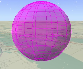
Ellipsoid Triangulator
The ellipsoid triangulator,
EllipsoidTriangulator, computes a
SolidTriangulatorResult for an ellipsoid centered at the
origin. The following example uses a solid primitive to visualize
an ellipsoid. Note that the code is nearly identical to the box
example.
| [C#] |
Copy Code
|
IAgStkGraphicsSceneManager
manager = ((IAgScenario)root.CurrentScenario).SceneManager;

IAgPosition origin =
root.ConversionUtility.NewPositionOnEarth();

origin.AssignPlanetodetic(28.488889, -80.577778, 4000);


Array radii = new object[] {2000, 1000, 1000 };

IAgStkGraphicsSolidTriangulatorResult result =
manager.Initializers.EllipsoidTriangulator.ComputeSimple(ref
radii);

IAgStkGraphicsSolidPrimitive solid =
manager.Initializers.SolidPrimitive.Initialize();

((IAgStkGraphicsPrimitive)solid).ReferenceFrame = system;

solid.SetWithResult(result);


manager.Primitives.Add((IAgStkGraphicsPrimitive)solid);

manager.Render();
|
|
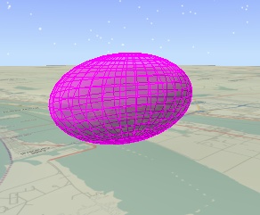
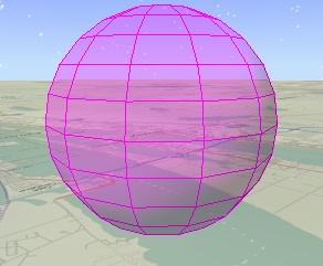
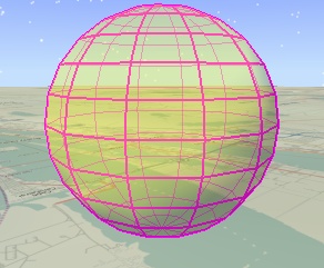
For more fine grain control over the shape of the ellipsoid, use
the
EllipsoidTriangulator.Compute method that takes the number of
slices around the z axis and number of stacks along the z axis. As
shown below, more slices and stack provide a more precise
ellipsoid, but use more memory.
|
![]()
|
![]()
|
![]()
|
|
Slices: 12
Stacks: 8
|
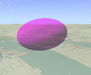
Slices: 24
Stacks: 8
|
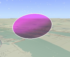
Slices: 12
Stacks: 16
|
Cylinder Triangulator
The cylinder triangulator,
CylinderTriangulator, computes a
SolidTriangulatorResult for a cylinder centered at the origin.
The
CylinderTriangulator.CreateSimple method takes two arguments:
the length of the cylinder along the z axis and the cylinder's
radius. The advanced Compute method includes different radii for
the bottom and top caps, the number of slices around the z axis,
and if the cylinder includes a bottom cap, top cap, and/or wall.
This enables creation of a wide range of shapes as shown below.
The cylinder for the leftmost image is created with the
following code.
| [C#] |
Copy Code
|
IAgStkGraphicsSolidTriangulatorResult result =
manager.Initializers.CylinderTriangulator.Compute(

4000, 1500, 1500, 180,
AgEStkGraphicsCylinderFill.eStkGraphicsCylinderFillAll);
|
|
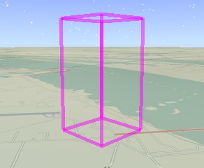
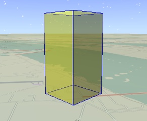
Fill and Outline
By default, a solid's interior fill and outline are displayed.
The fill can be customized with
DisplayFill,
Color,
Translucency, and
AffectedByLighting. The outline can be customized with
DisplayOutline,
OutlineColor,
OutlineTranslucency, and
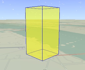
OutlineWidth. The following shows three possible combinations
of interior fill and outline.
The outline can be further customized using
OutlineAppearance. By default, the outline for both the front
side of the solid and the backside are displayed. For some solids,
such as ellipsoids with a high number of slices and stacks, the
outline on the backside can clutter the visualization. Use
OutlineAppearance.FrontLinesOnly to only display the outline on
the front side of the solid.
OutlineAppearance.StylizeBackLines is an alternative to
FrontLinesOnly that can also be used to declutter the outline
without eliminating the outline on the backside of the solid. When
StylizeBackLines is used, the backside outline is displayed
using a different color, translucency, and width as the front side
outline. This difference can be used to de-emphasize the backside
outline by giving it any combination of a lighter color, lower
translucency, or smaller width. When
StylizeBackLines is used, the backside outline is displayed
using
BackLineColor,
BackLineTranslucency, and
BackLineWidth. The following example uses a lower translucency
and smaller width to de-emphasize the backside outline.
| [C#] |
Copy Code
|
((IAgStkGraphicsPrimitive)solid).Color = Color.Yellow;

solid.OutlineTranslucency = 1; // Default

solid.OutlineWidth = 2;

solid.OutlineAppearance =
AgEStkGraphicsOutlineAppearance.eStkGraphicsStylizeBackLines;

solid.BackLineTranslucency = 0.5f;

solid.BackLineWidth = 1; // Default
|
|
STK Programming Interface 11.0.1