Precisions, Precisions |
While under development, the Insight3D development team wrote a series of blog posts, which are now archived here to provide in-depth technical information about some of the underlying techniques and design decisions. These posts reflect the work-in-progress state of the product at the time.
The following blog post was originally published on the Insight3D blog on September 3, 2008 by Deron Ohlarik. At the time of publishing, Insight3D was referred to by its development code-name, "Point Break".
Rendering objects over large distances is common for geospatial programs, and when done incorrectly, the objects may visually jitter. Here, an object is made up of any combination of triangles, lines, and points, like a 3D model. The problem becomes more noticeable as the viewer nears the object. The following video demonstrates this using STK. (Note that I had to modify STK as it does not ordinarily exhibit jitter.)
Rotating about the space shuttle from far away, there is no jitter. After zooming in, the jitter is readily apparent. In this blog entry, I'll discuss the cause of this problem and the solutions used in Point Break and STK.
Using graphics APIs such as OpenGL and Direct3D, graphics processing units (GPUs) internally operate on single precision 32-bit floating-point numbers that for the most part follow the IEEE 754 specification. Single precision values are generally said to have seven accurate decimal digits; therefore as your numbers become larger and larger, the numbers are less and less accurately represented. Chris Thorne describes the issue in his paper Using a Floating Origin to Improve Fidelity and Performance of Large, Distributed Virtual Worlds.
In Point Break and STK, placing objects precisely is of utmost concern. We would like to have at least 1 cm of accuracy. The largest number that allows approximate 1 cm increments is 131,071 (217 - 1), where whole numbers are in meters. The following code fragment shows floatValue being assigned in the code and in the comment that immediately follows, the value actually stored in CPU system memory. While the stored values are not exactly the assigned values, they are within 0.5 cm.
float floatValue;

floatValue = 131071.01; // 131071.0078125
floatValue = 131071.02; // 131071.0234375
floatValue = 131071.03; // 131071.0312500
floatValue = 131071.04; // 131071.0390625
floatValue = 131071.05; // 131071.0468750
floatValue = 131071.06; // 131071.0625000
floatValue = 131071.07; // 131071.0703125
floatValue = 131071.08; // 131071.0781250
floatValue = 131071.09; // 131071.0937500
If the above values were incremented by 1 m, the assigned values do not approximate the stored values on the order of 1 cm. In fact, some different assigned values are the same stored values.
float floatValue;

floatValue = 131072.01; // 131072.0156250
floatValue = 131072.02; // 131072.0156250
floatValue = 131072.03; // 131072.0312500
floatValue = 131072.04; // 131072.0468750
floatValue = 131072.05; // 131072.0468750
floatValue = 131072.06; // 131072.0625000
floatValue = 131072.07; // 131072.0625000
floatValue = 131072.08; // 131072.0781250
floatValue = 131072.09; // 131072.0937500
Given that the earth's maximum radius is 6,356,750 m, numbers far greater than 131,071 m are required to place an object on the surface or in orbit if the object's coordinates are relative to the earth's center. The object will not have sub-meter accuracy or worse. When the viewer zooms in closely to such an object, the object will jitter as shown in the above video.
If double precision 64-bit floating point numbers could be passed from the CPU to the GPU, and the GPU internally operated on double precision numbers, the jittering problems would not occur for objects rendered on or near the earth. (But just as with single precision values, accuracy is lost the farther an object is from the earth, and jittering will return. I haven't done the math; but, I would expect anything within the solar system would render without issue.)
There are several strategies for dealing with single precision issues.
When STK was designed in the 90's, jittering quickly manifested itself when rendering the earth and orbiting objects, such as the space shuttle. The solution was to render objects relative to the viewer similar to Chris Thorne's approach. The area of a pixel in world space close to the viewer is much smaller than the area far from the viewer; therefore, as the viewer approaches an object more and more accuracy is required to render the object without jitter. Rendering the objects relative to the viewer provides the required accuracy.
Here is an example of how the single precision ModelView matrix, MVGPU, that is sent through OpenGL to the GPU is calculated to render the space shuttle relative to the viewer. Using the double precision ModelView matrix, MVCPU, computed on the CPU for the viewer relative to the center of the earth, calculate the double precision space shuttle position relative to the viewer, SpaceShuttleEye from its world position, SpaceShuttleWorld.
SpaceShuttleEye = MVCPU * SpaceShuttleWorld
Initialize MVGPU from MVCPU. This requires a downward cast from the double to single precision values.
MVGPU = MVCPU
Next, assign SpaceShuttleEye to the translation part of the MVGPU. In the following, the matrix is in column major order where the first index is the row and the second index is the column. Once again, this is a downward cast from the double to single precision values. Note that the original translation values in MVGPU are large, while the values in SpaceShuttleEye become smaller as the viewer approaches the space shuttle. This is exactly what we want.
MVGPU 0, 3 = SpaceShuttleEye x
MVGPU 1, 3 = SpaceShuttleEye y
MVGPU 2, 3 = SpaceShuttleEye z
Here is the example again with actual numbers where the view is in close proximity of the space shuttle.
MVCPU =
0.000000  -0.976339   0.216245        -13.790775
0.451316  -0.192969  -0.871249   -7527123.004836
0.892363   0.097595   0.440638  -14883050.114944
0.000000   0.000000   0.000000          1.000000
SpaceShuttleWorld = (16678139.999999, 0.00000, 0.000000)
SpaceShuttleEye = MVCPU * SpaceShuttleWorld = (-13.790775, -11.572596, -95.070125)
Plugging these values into MVGPU results in:
MVGPU =
0.000000  -0.976339   0.216245  -13.790775
0.451316  -0.192969  -0.871249  -11.572596
0.892363   0.097595   0.440638  -95.070125
0.000000   0.000000   0.000000    1.000000
The first three rows in column three of MVGPU are the translation component of the matrix. These values are significantly smaller than the same in MVCPU. After submitting MVGPU to OpenGL, the object is rendered. This matrix will result in no jitter. The matrix must be recomputed each time the viewer moves; this is an insignificant cost when compared to rendering the thousands of vertices of the space shuttle model.
At AGI, we call this method rendering "relative to center" (RTC). Both Point Break and STK use this method.
The RTC method works fine for approximate cm accuracy as long as the vertices of the object are within 131070 m of the object center. (Actually, it is likely half that value, but I haven't had time to do the required analysis.) There is at least one case where that method will not work.
What if an object's vertices are separated by more than 131070 m? This is not uncommon as shown in Figure 1 when rendering satellite orbit lines, lines between objects, and geometric planes, such as an equatorial plane. There is no center that would prevent jitter.
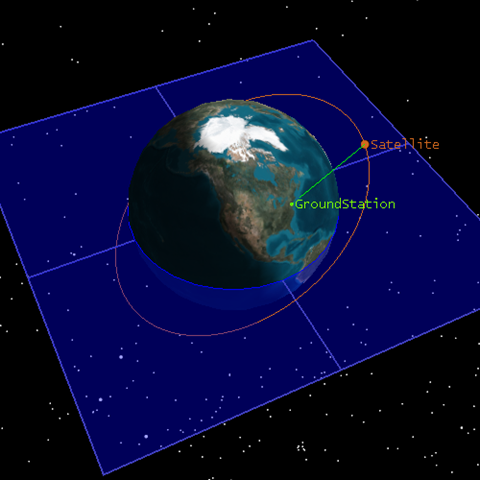
One option is subdivision. For example, the equatorial plane in Figure 1 is a square rendered using two triangles. The triangles could be subdivided until the vertices are separated by less than 131070 m. Clusters of triangles can then be formed where each cluster has its own center, and each vertex is no more than 131070 m from the center. Each cluster would then be rendered using the RTC method.
While this is a solution, subdivision is complicated, can result in performance issues in regards to animation frame rate, and is in some cases impossible. Subdivision is complicated in the sense that there are a wide variety of subdivision methods, some better suited than other for specific vertex arrangements; choose wisely. Performance is impacted, because rather than two triangles using four vertices, approximately 75,000 triangles using 150,000 vertices with many OpenGL draw calls that cause poor batching would be required to render the equatorial plane. There are cases where subdivision is not possible. I am skipping a discussion of such cases as it is only distracts from the precision issues. It suffices to say that subdivision is not a good solution. One additional note is that normally subdivision is done to add detail; this subdivision does not as all new triangles are in the same plane as their parent triangles.
The solution used in Point Break and STK is to render each of the object's vertices relative to the viewer. In this case, the ModelView matrix, MVGPU, submitted to OpenGL would only contain a rotation, no translation. For example:
MVGPU =
0.000000  -0.976339   0.216245  0.000000
0.451316  -0.192969  -0.871249  0.000000
0.892363   0.097595   0.440638  0.000000
0.000000   0.000000   0.000000  1.000000
The viewer position is subtracted from each vertex, and the object is rendered. At AGI, we call this method rendering "relative to eye" (RTE).
In the case of the equatorial plane each time the viewer moves, the viewers position must be subtracted from the four vertices. This is a performance hit, but nothing like the performance hit that a subdivision solution would cause.
The drawback to this method is the very thing that makes it work - the per vertex subtraction of the viewer position that must occur at a minimum whenever the viewer position changes. If the object comprised many vertices, the process could spend more time preparing the data on the CPU than rendering the data on the GPU. Also, static VBOs, the fastest rendering method in OpenGL, cannot be used, since the vertices sent to the GPU are constantly changing.
There is a GPU based method that eliminates the main drawback to the RTE method. The key is to improve the accuracy of the math executed on the GPU beyond the GPU's single precision limitations.
Generally, vertices in Point Break and STK are computed in double precision. The vertices are converted to single precision when sent to OpenGL. Instead of that for the GPU RTE method, each double precision value is encoded into two single precision values on the CPU; the two single precision values are then sent to the GPU where a GLSL vertex shader uses the two single precision values to compute the difference between the viewer and vertex positions. While we will not get full double precision, we will get a number that easily handles our typical use cases.
A floating point value is composed of three parts: 1 sign bit, 8 exponent bits, and 23 fraction bits. Again refer to the IEEE 754 specification to understand how values are encoded.
A double is encoded into two floats, a high and low. In the low float, 7 of the 23 fraction bits are used for the part of the double after the decimal point, which means that the resolution of the number is 2-7, 0.0078125. This is less than a cm. The remaining 16 bits are used to represent an integer value from 0 to 65535 (216 - 1) in 1 increments.
The high part uses all 23 bits to represent the numbers 65,536 to 549,755,748,352 ((223 - 1) * 65536) in 65536 increments.
If you are familiar with the IEEE 754 specification, there is an additional unsaid bit of precision, such that there are actually 24 fraction bits. Why isn't that bit used here? That bit is used to capture overflows when two lows or two highs are added or subtracted from each other.
The maximum whole number that can be encoded is 549,755,748,352. Here are some numbers in relation to the distances between some planets and the Sun to get an idea of that number's size.
Planet | Distance from the Sun (m) |
|---|---|
Mercury | 69,800,000,000 |
Earth | 152,000,000,000 |
Mars | 249,000,000,000 |
Jupiter | 817,000,000,000 |
These two encoded floats can represent a very large distance with sub-centimeter accuracy along one dimension. The maximum error in an x, y, z position is (3 * 0.00781252)1/2, 1.353 cm. While not 1 cm accuracy, this is close, and we could double the accuracy along one dimension if we halve the maximum value. That should not be an issue if we only rendered near earth; however, we are interplanetary at AGI. (Our code will fall back to the CPU RTE method if distances greater than 549,755,748,352 m are required to define the position. This is very unlikely.)
The code to convert the double to two floats is:
void CDoubleToTwoFloats::Convert(double doubleValue,
    float& floatHigh, float& floatLow)
{
    if (doubleValue >= 0.0)
    {
        double doubleHigh = floor(doubleValue / 65536.0) * 65536.0;
        floatHigh = (float)doubleHigh;
        floatLow = (float)(doubleValue - doubleHigh);
    }
    else
    {
        double doubleHigh = floor(-doubleValue / 65536.0) * 65536.0;
        floatHigh = (float)-doubleHigh;
        floatLow = (float)(doubleValue + doubleHigh);
    }
}
Let's next examine how the positions are passed to OpenGL. In the CPU method, each position is placed into a dynamic VBO using the vertex array attribute. In the GPU method, each position is placed into a static VBO split into two parts: one part as a vertex array attribute and one part as a normal array attribute. (While we are using the normal array in this example, any of the other array attributes would work.) Once in the VBO, the CPU never has to touch the positions again, thus eliminating the main drawback to the CPU method. The method can no longer become CPU limited, and it uses the fastest rendering method in OpenGL, the static VBO.
The vertices are processed on the GPU using this GLSL vertex shader:
uniform vec3 uViewerHigh;
uniform vec3 uViewerLow;

void main(void)
{
    vec3 highDifference = vec3(gl_Vertex.xyz - uViewerHigh);
    vec3 lowDifference = vec3(gl_Normal.xyz - uViewerLow);
    gl_Position = gl_ModelViewProjectionMatrix *
         vec4(highDifference + lowDifference, 1.0);
}
(This shader shows only the position processing; a typical vertex shader would contain more, such as normal and texture coordinate processing.)
The uniforms uViewerHigh and uViewerLow are the double precision viewer position encoded as two floats. The high difference between the vertex attribute and viewer position are separately calculated from the low to maintain their respective precisions. After the subtractions, they are then added together. This is where the miracle occurs.
When the viewer is far from the object, the high difference will swamp out the low difference. This is fine as the viewer is far away and will see no jitter. When close, less than 65536 meters, the high difference is zero, and the low difference is preserved. Again, the viewer will see no jitter. This is exactly what we want at the cost of just two vector subtractions.
In testing, the GPU method clearly outperforms the CPU method. The performance varies depending on the CPU load. I hope to publish numbers in the future.
One drawback to this method is that the position data doubles in size from one to two floats. This has performance implications as this data must be transferred to the GPU if not already there. More data generally results in lower performance. In the worst case, 100% more data is transferred; however, a typical vertex is 32 bytes: 12 bytes for a position, 12 bytes for a normal, and 8 bytes for a texture coordinate. Using this method the vertex would be 44 bytes, an additional 37.5%. Not so bad. Another problem in this case though is that the vertex exceeds the 32 byte cache line on the GPU which could reduce performance.
When placed in perspective, the method actually reduces the amount of data required. Remember that this method is used when the only way to use the RTC method would be to subdivide the geometry. Subdivision would result in some number of new vertices. As in the equatorial plane example above, the amount of memory needed for the new vertices could far exceed that of this method.
There still might be a precision issue requiring further study. Certainly, if the viewer approaches one of the corners of the equatorial plane, the corner will not jitter. What would happen if the viewer approached an edge midway between two vertices? The edge may jitter as the vertices that define that edge are very far away. Surprisingly, I haven't tested this. We have used the CPU RTE method for years in STK for a variety of purposes. None of our customers have complained of this issue. (I confess though that our STK geometric plane rendering code does not use this method and does indeed suffer from jitter. That will be remedied soon, and then I can perform the described test.)
Thankfully, all these precision issues are insulated from the Point Break user. The user creates primitives or submits their own vertices, and Point Break decides which precision method to use. How Point Break decides this, as performance is also a consideration, could be a whole other blog. It hurts my brain to even think about it.
It would be interesting to use the GPU RTE method to render the entire earth. Many terrain algorithm are variants of geomipmapping where the terrain is divided into a tiles of varying resolutions and placed in a tree. (Point Break uses a variant of Ulrich's Chunked LOD, where the tiles are referred to as chunks.) Each tile has its own center. The tiles are rendered with the RTC method.
Many of these algorithms restrict the geographic size of the tiles to ensure accurate placement using single precision values. The P-BDAM algorithm takes particular care with this. If that restriction were removed, I wonder how those algorithms might change? I also am unsure how texture coordinates would be calculated as they have their own precision issues. This would be an interesting problem to think about if I had more time.
MMORPG is a game genre in a large virtual world. The world is often divided into zones in part to prevent the jitter problem. The GPU RTE method would allow the game designers to create one continuous world. Zones might still be needed for other reasons, but their size would no longer be constrained based on jitter concerns. Movement through the world might be simplified. I am not in the game industry, so forgive me if these ideas a bit off.
Would the GPU RTE method be of use in computer-aided design (CAD) where rendering accuracy is very important? I can imagine using GPU RTE for the entire CAD model. A double precision value could be encoded where all of the low bits represent numbers after the decimal point and the high bits represent integer values that increment by 1 m. The largest whole number would be 8,388,607 (223 - 1) which is more than enough for most models, while the number's fractional resolution is 0.00000011920928955078125 (2-23). Of course, the accuracy could be increased or decreased as required. Again not being in the CAD industry, I am unsure how CAD graphics programmers handle accurately positioning vertices now.
There you have it - the first installment of Precisions, Precisions. Sometime in the future I expect to discuss a texture mapping precision problem we recently corrected. Be prepared for excruciating detail.