Trapezoidal Texture Projection with OpenGL |
While under development, the Insight3D development team wrote a series of blog posts, which are now archived here to provide in-depth technical information about some of the underlying techniques and design decisions. These posts reflect the work-in-progress state of the product at the time.
The following blog post was originally published on the Insight3D blog on November 21, 2009 by Deron Ohlarik.
All surface images in Insight3D are placed on the Earth where the edges of the image align with latitudinal and longitudinal lines and the top edge is north. Several customers have asked if they could map an image where that is not the case, where they have the latitude and longitude coordinates of each corner.
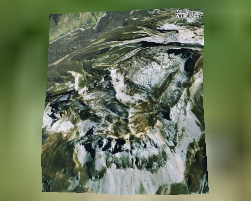
Figure 1 shows an image captured from the viewpoint of a simulated UAV camera. While the image itself is exactly as it was, the image is not correctly positioned on the terrain. As mentioned, the image edges align with latitudinal and longitudinal lines.
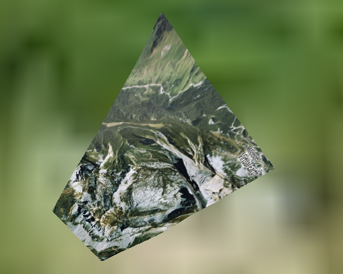
In Figure 2, the image's corners have been mapped from their original coordinates to their actual coordinates. One can tell that the camera took this image from the southwest.
This capability has been added to Insight3D's Surface Mesh Primitive for our upcoming r8 release. I'll wait until r8 is out to discuss the new interfaces and how this method differs from projecting an image onto the terrain.
In this post, I'll discuss how we use OpenGL to remap the image of Figure 1 to that of Figure 2.
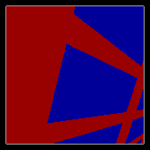
The goal is to remap the texture coordinates from one trapezoid to another. Let's begin with an example. Figure 3a shows an image, a blue square with a red border, mapped to a square, while the other figures show a remapping of that square to a trapezoid with an outline of the original square shown as reference.
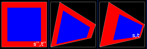
One obvious way to map to the trapezoid would be to just move the vertices. In Figure 3b, the vertex positions have been moved while the texture coordinates remain that same as in Figure 3a. This results in an orthographic projection where the texture coordinates are linearly interpolated across the trapezoid. Given that we want a perspective projection, this is incorrect.
In Figure 3c, the vertex positions have been moved, and the texture coordinates have been altered. This trapezoid appears to be a rectangle closer to the viewer on the left side and farther away on the right; however, the trapezoid is actually in a plane perpendicular to the viewer, i.e. flat to your display. A perspective transform has been applied to the texture coordinates. This is how the UAV image should be placed onto the terrain. How is this transform computed?
A texture coordinate is defined by the vector (s, t, r, q). Most graphics developers are familiar with using s and t to map a 2D texture to a triangle; in this case, r and q default to 0 and 1 respectively. The value r is used for 3D textures and so is ignored here. I'll get to q in a moment.
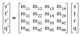
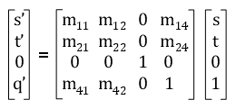
In the OpenGL fixed function pipeline, each texture coordinate (s, t, r, q) is multiplied by a 4x4 texture matrix as shown in Equation 1.
Since OpenGL interprets (s', t', r', q') as a homogeneous coordinate, s', t', and r' are next divided by q' as shown in Equations 2, 3 and 4. This is the perspective divide, and is necessary to produce Figure 3c.
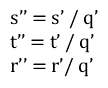
Coordinate (s'', t'', r'') is used to sample the texture. For a 2D texture, only s'' and t'' are used.
Remapping requires a texture matrix that maps (s, t) in Figure 3c to (s'', t'') in Figure 3a.
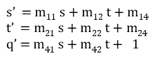
Since only a 2D texture is being considered, the 3D components of the matrix and vectors are zeroed out; m44 is set to 1 as this is a homogenous matrix; m33 is inconsequential as that value is multiplied by 0 in the matrix multiplication.
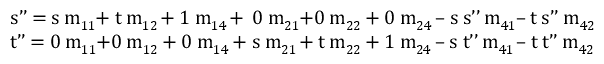
After multiplication:
After multiplying both sides of Equations 2 and 3 by q', and then plugging in Equations 6, 7, and 8:
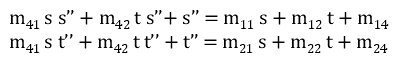
Equations 9 and 10 are rearranged to form two linear equations.
There are eight unknown matrix components to solve. The mapping for the corners to go from Figure 3c to Figure 3a are:
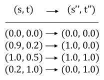
This yields eight equations with eight unknowns. Using a linear equation solver, the texture matrix can be computed.
If you are using the OpenGL fixed function pipeline, after loading this matrix to the OpenGL matrix stack, there are two basic ways to render the texture and geometry.
You can move the vertex positions and use the (s, t) texture coordinates.
Alternatively, you could keep the original vertex positions and (s'', t'') texture coordinates. You will have to specify a border color for the texture.
float borderColor[4] = {126.0f, 126.0f, 126.0f, 0.0f};
glTexParameterfv(GL_TEXTURE_2D, GL_TEXTURE_BORDER_COLOR, borderColor);
glTexParameteri(GL_TEXTURE_2D, GL_TEXTURE_WRAP_S, GL_CLAMP_TO_BORDER);
glTexParameteri(GL_TEXTURE_2D, GL_TEXTURE_WRAP_T, GL_CLAMP_TO_BORDER);
When rendering, you must enable the alpha test.
glAlphaFunc(GL_GREATER, 0.0f);
glEnable(GL_ALPHA_TEST);
If you do not, the texture will bleed beyond its border as shown in Figure 5.
Of course if you are using shaders instead of the fixed function pipeline, you can still easily do either way. There are various other combinations that will work too.
Our unique method for rendering the surface mesh primitive requires that we use the second method.