EOIR supports up to 36 bands per sensor. Bands share a common location and Line of Sight, but otherwise can have different parameters. Two typical uses for bands are to simulate:
- Different wavelength response capabilities -- a multi-band sensor.
- Different image magnifications -- different settings of a zoom lens.
To define an EOIR sensor, go to the Sensor-->Definition-->properties page, and select EOIR as the Sensor Type.
For an example of how to use EOIR and STK to measure the visual magnitude of stars, see Shining a Light on Visual Magnitude.
Adding Bands
Add bands to an EOIR sensor using the following options:
Add. Adds a new band with default parameters. A band ID is automatically assigned.
Remove. Removes the selected band.
Defining Bands
You can define the following types of properties for each band in an EOIR sensor:
To view or modify the properties for a particular band, select it in the band table. The spatial, spectral, optical and radiometric properties will be refreshed with values of the highlighted band.
Sensor Level Properties
You can also define the following properties for the EOIR sensor:
Processing Level
Select the type of calculation performed by this EOIR Sensor-Scene Generator pair:
Sensor Off. No processing is performed.
Geometric Input. Only the geometric information in the sensor scene is calculated and displayed. Relative shading of objects is based on the temperature of their thermal models. This selection is helpful for more rapidly stepping through a series of scenes [through time] until arriving at a scene of interest or creating a temperature map.
Radiometric Input. Full synthetic sensor scene generation is performed, including both geometric and radiometric aspects; however, no optical or detector effects are applied. This output is often called entrance aperture radiance.
Sensor Output. The EOIR sensor model operates on the sensor scene and calculates the corresponding sensor output image.
Each of these successive modes is more computationally intensive and will require more time to generate an image.
Scan Mode . 2D Framing Array is the type of Scan Mode specification used for the processing level calculation.
Show Motion Blur
During the integration time, both the sensor and the objects in the scene are potentially moving. By checking this box, motion blur will be simulated for area targets as the gross sensor rotation during the integration time period and for point sources as their straight line of motion from their relative sensor position at the start of the integration time to the current scenario time.
Smear Rate Along Scan. The along-scan smear rate of the EOIR sensor relative to the sensor up vector.
Smear Rate Across Scan. The across-scan smear rate of the EOIR sensor relative to the sensor up vector.
Jitter
Select the jitter type:
LOS Gaussian. LOS Gaussian jitter type specification.
MTF File. Frequency modulation transfer function file type specification.
PSF/Realization File. Spatial point spread function file type specification.
Power Spectrum File. Power spectrum file type specification.
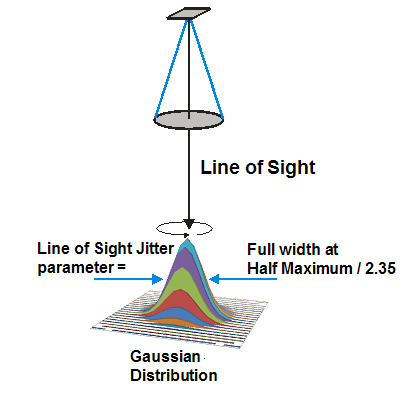
Line of Sight Jitter. Vibrations of a sensor's parent object can cause the Line of Sight to move during integration time, blurring the image. The angle entered describes the dimension of an assumed Gaussian motion of the Line of Sight, and is interpreted as (Full Width at Half Maximum)/2.35.
Data File. Jitter description data file.
Data File Sampling. Jitter data file frequency or spatial sampling.
 Visit AGI.com