Part 15:
STK Premium (Air) or STK Enterprise
You can obtain the necessary licenses for this tutorial by contacting AGI Support at support@agi.com or 1-800-924-7244.
This lesson requires version STK 12.1 of the STK software or newer to complete in its entirety.
The results of the tutorial may vary depending on the user settings and data enabled (online operations, terrain server, dynamic Earth data, etc.). It is acceptable to have different results.
Capabilities covered
This lesson covers the following capabilities of the Ansys Systems Tool Kit® (STK®) digital mission engineering software:
- STK Pro
- Aviator
Problem statement
Aircrew mission planners require analytical tools that allow them to determine how atmospheric phenomena and terrain will affect the performance of an airborne mission. Furthermore, they need the ability to model real-world aircraft performance that accounts for variations in airframe performance characteristics and mission requirements. In this lesson, you want to fly a small commuter jet from the City of Colorado Springs Municipal Airport to Telluride Regional airport using Navigational Aids (NAVAIDs) as waypoints. You want to determine how much fuel is required and how much payload can be carried on board the aircraft in a fast, easy way.
Solution
Use the STK software's Aviator capability to:
- Design a cross-country flight route by defining elements of a mission
- Load airfield runway data into the scenario for takeoff and landing procedures using the Aviator Catalog Manager
- Add NAVAIDs using the Aviator catalog interface to simulate physical devices on the ground that aircraft can detect and fly to along its route
- Determine payload requirements and the amount of fuel consumed during the flight using selected Data Providers
What you will learn
Upon completion of this tutorial, you will understand the following:
- How to use the Aviator Catalog Manager and Aviator catalog interface to insert mission elements
- How to create Analytical Objects from the Aviator Catalog Manager
- How to model an aircraft mission using the Aviator propagator
- How to use Aviator tools to define an aircraft and to create and modify phases and procedures of a mission
Video guidance
Watch the following video. Then follow the steps below, which incorporate the systems and missions you work on (sample inputs provided).
Creating a new scenario
First, you must create a new scenario and then you will build from there.
- Launch the STK application (
 ).
). - Click
 Create a Scenario in the Welcome to STK dialog box.
 - Enter the following in the STK: New Scenario Wizard:
- Click when you finish.
- Click Save (
 ) when the scenario loads. The STK application creates a folder with the same name as your scenario for you.
 - Verify the scenario name and location in the Save As dialog box.
- Click .
| Option | Value |
|---|---|
| Name | STK_Aviator |
| Location | Default |
| Start | Default (recommend changing the time to 18:00:00.000 UTCG for daylight) |
| Stop | + 1 hr |
Save (![]() ) often during this lesson!
) often during this lesson!
Decluttering labels in the 3D Graphics window
Your analysis will take place in very mountainous terrain, which can obstruct object labels. Enable the Label Declutter option to separate the labels on objects that are in close proximity for better identification in small areas.
- Bring the 3D Graphics window to the front.
- Click Properties (
 ) in the 3D Graphics window Default toolbar.
 - Select the Details page when the Properties Browser opens.
- Select the Enable check box in the Label Declutter panel.
- Click to accept the change and to close the Properties Browser.
Understanding the Aviator capability
The STK software's
An aircraft using Aviator as its propagator can carry out operations that are more complex than a just a transit between two points. The process of defining a mission in Aviator, therefore, encompasses much more than merely selecting route points. A mission includes the flight procedures and performance characteristics of the aircraft and describes not only where the aircraft goes, but how it goes there and what it does along the way.
Whether a mission is as simple as a transit between two points, or as complex as a patrol mission in which the aircraft has been retasked to respond to a threat, the method for designing a mission is the same in principle. To define a mission, you must:
- Select and configure the aircraft model that you wish to use
- Insert and define the phases of the mission and select the performance models you wish to employ in each
- Insert and define the procedures that the aircraft will execute in each phase
To aid in mission design and planning, Aviator provides a catalog structure for the loading and saving of aircraft, airports, NAVAIDs, runways, VTOL points, and waypoints. Each of these mission elements has an associated catalog in the STK application.
Using the Aviator Catalog Manager
The Aviator Catalog Manager is a utility that allows you to view the contents of catalogs, create new items, copy or edit existing items, and search for specific items. You can use the Aviation Catalog Manager to import catalogs of compatible data to define mission elements like runways and waypoints. To aid in your mission design, use the Aviation Catalog Manager to load an ARINC424 data file containing navigation information into your scenario.
Loading navigation data using the Aviator Catalog Manger
Open the Aviator Catalog Manager from the Utilities menu and load a ARINC424 data file containing navigation information. ARINC424 data files are the only valid data sources for NAVAID and airport sites.
- Select Aviator Catalog Manager... (
 ) in the Utilities menu.
 - Resize the Aviator Catalog Manger window by extending it out to the right so that you can see more space in the large blank area.
- Expand (
 ) Runway (
 ).
). - Select ARINC424 runways (
 ).
). - Click the Use Master Data File ellipsis (
 ).
). - Navigate to <Install Dir>\Data\Resources\stktraining\samples when the Open dialog box appears.
- Select the FAANFD18 data file.
- Click to select the file and to close the Open dialog box.
- Click when you return to the Aviator Catalog Manager.
Determining the length of a runway
The aircraft will fly to and land at Telluride Regional Airport that is located in Telluride, Colorado. Determine the length of the runway using the information displayed in the Aviation Catalog Manager.
- Enter Telluride in the Filter field.
- Select the Enter key.
- Select TELLURIDE RGNL 09 27 (
 ) in the list under ARINC424 runways ().
 - Examine at the properties on the right.
- Locate the Length field. The runway at Telluride Regional Airport is 7,111 feet long.
Note that TELLURIDE RGNL 09 27 (![]() ) is marked with a red dot (
) is marked with a red dot (![]() ). Items marked with a red dot in the Aviator Catalog Manager and the Aviator catalog interface are read only and cannot be modified.
). Items marked with a red dot in the Aviator Catalog Manager and the Aviator catalog interface are read only and cannot be modified.
When looking at runway data in the Aviator Catalog Manager, the two numbers next to the runway are reciprocal headings of the runway. For instance, 09 is 90 degrees (meaning it points east) and 27 is 270 degrees (meaning it points west). If you're landing on runway 09, you are approaching it from the west. If there is more than one runway pointing in the same direction (that is, parallel runways), each runway is identified by appending left (L), center (C) and right (R) to the number to identify its position, when facing its direction; for example, runways one-five-left (15L), one-five-center (15C), and one-five-right (15R) are parallel runways on headings of 150 degrees.
Inserting analytical objects from the Aviator Catalog Manager
The small commuter jet will take off from the City of Colorado Springs Municipal Airport and land at Telluride Regional Airport. The Telluride Regional Airport runway sits on a plateau and dips slightly in the center, which can provide a challenging landing for the pilot. Weather conditions in the area often rapidly change, and pilots must be aware of issues impacting the airfield, such as high terrain exceeding 14,000 feet as well as the runway's location on a plateau with a 1,000-foot drop should the aircraft slide off of the runway.
Use the Aviator Catalog Manager to insert the Telluride Regional Airport and the City of Colorado Springs Municipal Airport as Place objects into the scenario.
Inserting the Telluride Regional Airport
Add the runway at Telluride Regional Airport as a Place object. The center point of the runway will form the coordinates of the Place object.
- Right-click on TELLURIDE RGNL 09 27 () under ARINC424 runways ().
- Select Create STK Object from waypoint... in the shortcut menu.
- Open the Type of Object drop-down list in the Create STK Objects window.
- Select Place.
- Click to close the Create STK Objects window.
Inserting the City of Colorado Springs Municipal Airport
Add a runway at the City of Colorado Springs Municipal Airport as a Place (![]() ) object.
) object.
- Enter Colorado Springs in the Filter field.
- Select the Enter key.
- Right-click on CITY OF COLORADO SPRINGS MUNI 17L 35R () in the list under ARINC424 runways ().
- Select Create STK Object from waypoint... in the shortcut menu.
- Open the Type of Object drop-down list in the Create STK Objects dialog box.
- Select Place.
- Click to close the Create STK Objects dialog box.
- Close (
 ) the Aviator Catalog Manager when finished.
Obtaining situational awareness
Now that you have the center points of both runways entered as Place objects, you can quickly zoom to them to view the runways and surrounding terrain features.
- Bring the 3D Graphics window to the front.
- Right-click on CITY_OF_COLORADO_SPRINGS_MUNI_17L_35R (
 ) in the Object Browser.
 - Select Zoom To in the shortcut menu.
- Use your mouse to change the view so that you can view the runway and its surroundings.
- Zoom to TELLURIDE_RGNL_09_27.
- Use your mouse to change the view so that you can view the runway and its surroundings.

City of colorado springs municipal airport
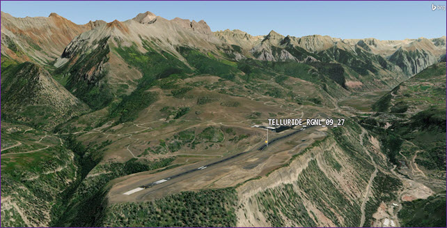
Telluride regional airport
Inserting an Aircraft object
Insert an Aircraft object, which you will use to create a flight plan.
- Bring the Insert STK Objects tool to the front.
- Select Aircraft (
 ) in the Select An Object To Be Inserted list.
 - Select Insert Default () in the Select A Method list.
- Click .
- Right-click on Aircraft1 () in the Object Browser.
- Select Rename in the shortcut menu.
- Rename Aircraft1 () Mission_Acft.
Selecting Aviator as the propagator
With Aviator, the aircraft's route is modeled by a sequence of curves parametrized by well-known performance characteristics of aircraft, including cruise airspeed, climb rate, roll rate, and bank angle. The precise state of an aircraft at any given time can be computed analytically — swiftly, and without excessive data storage needs. To use this capability, you must first set your aircraft to use Aviator as its propagator.
- Right-click on Mission_Acft () in the Object Browser.
- Select Properties ().
- Select the Basic - Route page when the Properties Browser opens.
- Open the Propagator drop-down list.
- Select Aviator.
- Click to accept the change and to keep the Properties Browser open.
- Read the information in the Flight Path Warning dialog box.
- Click .
- Click to close the Fight Path Warning dialog box.
Configuring an Aviator mission
The mission window is used to define the aircraft's route when Aviator has been selected as the propagator. The mission window contains three toolbars — Initial Aircraft Setup, Phases of Flight, and Procedures and Sites — that enable you to define the aircraft that you are modeling and to create, modify, and delete phases and procedures. The mission list provides an overview of the mission by listing each of the mission phases and the procedures within them, in the order in which they will be executed. The mission profile can display a variety of data describing the mission.
Selecting an aircraft model
The buttons on the Initial Aircraft Setup toolbar are used to define the aircraft model that will be used in the mission. The basic models found in Select Aircraft dialog box are representative of an aircraft type, but not a specific aircraft. It's up to you to customize the model you choose to match actual aircraft characteristics. Since this is an introduction to Aviator, you will only make some minor changes.
- Click Select Aircraft (
 ) In the Initial Aircraft Setup toolbar.
 - Right-click on Basic Business Jet (
 ) in the User Aircraft Models () list in the Select Aircraft dialog box.
 - Select Duplicate in the shortcut menu.
- Right-click on Basic Business Jet Copy ().
- Select Rename in the shortcut menu.
- Rename Basic Business Jet Copy () to COS_to_TEX.
- Select COS_to_TEX () in the User Aircraft Models () list.
- Click to close the Select Aircraft dialog box.
- Click to accept your changes and to keep the Properties Browser open.
Note that Basic Business Jet (![]() ) is read only (
) is read only (![]() ). To make any modifications, you must first copy the model.
). To make any modifications, you must first copy the model.
COS is the IATA airport code for City of Colorado Springs Municipal Airport and TEX for Telluride Regional Airport.
Editing performance models
Aircraft Properties provide access to performance models. Performance models are used to define the behavior of the aircraft in flight. By specifying performance models to use with each phase of the mission, you can vary the manner in which the aircraft performs based on the priorities of the mission. You'll use default settings mostly.
The Basic tab is comprised of three sections - Level Turns, Climb and Descent Transitions, and Attitude Transitions. You want to determine how much fuel is consumed during the flight and the weight of the mission aircraft when it lands.
The Aerodynamics tab is used to define the methods used to compute lift, drag, angle of attack The angle between the body X axis and the projection of the velocity vector onto the body XZ plane. The velocity vector is the velocity of the object as observed in the object's central body fixed coordinate system., sideslip and intermediate / derived values.
- Click Aircraft Properties (
 ) in the Initial Aircraft Setup toolbar.
 - Select the Acceleration () Built-In Model (
 ) in the COS_to_TEX dialog box.
 - Select the Aerodynamics tab.
- Open the Strategy drop-down list.
- Select HighFast.
- Read the data in the AeroProp Warning dialog box.
- Click to accept your changes and to close the AeroProp Warning dialog box.
The High Fast aerodynamics strategy uses thrust to generate a lift vector, which provides the ability to track fuel burn during lift. Additionally, it generates the forces perpendicular to the velocity vector to provide maneuvering.
The High Fast aerodynamics strategy must be paired with its High Fast propulsion counterpart.
Changing the Cruise Performance Model parameters
The Basic Cruise performance model is comprised of a simple set of parameters that define the flight characteristics of the aircraft during level flight. Since this is a fairly short flight, the aircraft will climb to 25,000 feet and level off.
- Select the Cruise () Built-In Model ().
- Enter 25000 ft in the Default Cruise Altitude field.
- Click .
- Click to close the COS_to_TEX dialog box.
Inserting the Aircraft Configuration settings
The Aircraft Configuration dialog box is used to define the aircraft's fuel and payload configuration. The Basic tab is used to define the empty parameters of the aircraft, and displays the total values, based on the stations and fuel tanks defined for it.
- Click Configuration (
 ) in the Initial Aircraft Setup toolbar.
 - Select the Basic tab when the Aircraft Configuration dialog box opens.
- Enter 31000 lb in the Empty Weight field.
- Note the Max Landing Weight value of 40000 lb.
- Note the Total Weight value of 51000 lb.
This is where you add payload weight. For instance, this will account for the pilot, instructor, any passengers and baggage.
This is the empty weight plus the default fuel weight of Mission_Acft (![]() ), which is 20,000 pounds of fuel.
), which is 20,000 pounds of fuel.
Understanding the Stations tab
The Stations tab is used to define internal fuel tanks, stations, and external fuel tanks that are attached to the stations.
- Select the Stations tab.
- Select Internal Fuel (
 ).
). - Note the Capacity and Initial state values.
- Click to accept your changes and to close the Aircraft configuration dialog box.
- Click to accept changes and to keep the Properties Browser open.
After your initial analysis, you may need to adjust the initial state.
Adjusting the Mission Wind Model
Use the
- Click Mission Wind Model (
 ) in the Initial Aircraft Setup toolbar.
 - Note that the Model Type defaults to Constant Bearing/Speed.
- Enter 180 deg in the Wind Bearing field in the Wind panel when the Mission_Acft (UI) wind/atmosphere model dialog box opens.
- Enter 20 nm/hr in the Wind Speed field.
- Click to accept your changes and to close the Mission_Acft (UI) wind/atmosphere model dialog box.
- Click to accept the changes and to keep the Properties Browser open.
Building the phases of flight with sites and procedures
Every mission must have at least one
Each phase is composed sites and procedures. A
Your aircraft's mission will have a single phase. It will take off from the City of Colorado Springs Municipal Airport and fly direct to the Blue Mesa VOR/DME. A VOR/DME is a radio beacon that combines a VHF omnidirectional range (VOR) with a distance measuring equipment (DME). Turning at the Blue Mesa VOR/DME, the aircraft will fly to the Cones VOR/DME, then begin its final approach to and land at Telluride Regional Airport.
Selecting the takeoff runway
If you have ARINC424 airport data available in the Aviator Catalog Manager, you can define a site using an airport in that data.
- Click Insert Procedure After (
 ) in the Procedures and Sites toolbar.
 - Select Runway from Catalog (
 ) in the Select Site Type list in the Site Properties dialog box.
 - Enter Colorado Springs in the Filter field.
- Select the Enter key.
- Select CITY OF COLORADO SPRINGS MUNI 17L 35R () Under ARINC424 runways ().
- Click .
Selecting the Takeoff procedure
A Takeoff procedure launches an aircraft from a runway site into the air.
- Select Takeoff (
 ) in the Select Procedure Type list in the Procedure Properties dialog box.
 - Set the following options:
- Click .
- Click to apply the changes and to keep the Properties Browser open.
| Option | Value |
|---|---|
| Name | COS Runway |
| Runway Heading The direction that the aircraft is pointing. - Use headwind runway | Selected |
| Runway Altitude Offset | 7 ft |
| Use Terrain for Runway Altitude | Selected |
You set runway altitude offset to seven feet. Most aircraft models used in the STK application have their center point in the middle of the 3D Graphics model. You have to adjust this if you don't want your aircraft to appear half buried in the terrain.
Inserting an End of Previous Procedure site type
The end of the previous procedure can be used as a waypoint to define the site of the next procedure. In this instance, due to terrain, you want to gain altitude prior to flying to Blue Mesa VOR/DM, which is located in mountainous terrain.
- Click Insert Procedure After () in the Procedures and Sites toolbar.
- Select End of Previous Procedure (
 ) in the Select Site Type list in the Site Properties dialog box.
 - Enter Climb in the Name field.
- Click .
Selecting a Basic Maneuver procedure
A Basic Maneuver procedure is a single action undertaken by the aircraft. It is unlike most procedures in Aviator, which represent sets of actions that together comprise a common flying procedure.
- Select Basic Maneuver (
 ) in the Select Procedure Type list in the Procedure Properties dialog box.
 - Enter Straight 25 nm in the Name field.
- Select the Horizontal / Navigation tab.
- Note that Straight Ahead is selected for the Strategy.
- Open the Strategy drop-down list to view other strategies.
- Leave Strategy set to Straight Ahead when done.
- Set the following options in the Basic Stop Conditions panel:
| Option | Value |
|---|---|
| Time of Flight | Clear |
| Downrange | 25 nm |
This procedure will end if your aircraft reaches zero pounds of fuel or flies straight ahead for 25 nautical miles, whichever comes first.
Selecting the vertical / profile strategy
Vertical / Profile strategies can be specified for non-3D maneuvers.
- Select the Vertical / Profile tab.
- Open the Mode drop-down list in the Altitude panel.
- Select Specify Altitude Change.
- Enter 10000 ft in the Relative Altitude Change field.
- Click two times.
- Click to apply the changes and to keep the Properties Browser open.
In the Mission Profile, you can see that the aircraft climbs 10,000 feet in altitude from the end of its COS Runway procedure.
Selecting the Blue Mesa NAVAID
If you have ARINC424 NAVAID data available in the Aviator Catalog Manager, you can define a site using a NAVAID from that data.
- Click Insert Procedure After () in the Procedures and Sites toolbar.
- Select Navaid from Catalog (
 ) in the Select Site Type list in the Site Properties dialog box.
 - Enter HBU in the Filter field.
- Select the Enter key.
- Right-click on HBU (
 ) in the ARINC424 navaids(
 ) list.
 - Select Create STK Object from waypoint... in the shortcut menu.
- Open the Type of object drop-down list in the Create STK Objects dialog box.
- Select Place.
- Click to close the Create STK Objects dialog box.
- Click .
HBU is the FAA designator for the Blue Mesa VOR/DME near Gunnison, Colorado.
Note that HBU (![]() ) is read-only (
) is read-only (![]() ).
).
Selecting a Basic Point to Point procedure
A Basic Point to Point procedure is a basic traverse between two waypoints.
- Select Basic Point to Point (
 ) in the Select Procedure Type list in the Procedure Properties dialog box.
 - Set the following options:
- Click .
- Click to apply the changes and to keep the Properties Browser open.
| Option | Value |
|---|---|
| Name | Blue Mesa |
| Navigation Options - Nav Mode | Fly Direct |
| Enroute Options - Turn Factor | 5.00 |
Setting the Nav Mode to Fly Direct tells the aircraft to fly direct to Blue Mesa. The Turn Factor is the maximum amount, expressed as a multiplier, that the turn radius will be increased to minimize the bank angle required to complete the turn.
Selecting the Cones NAVAID
Add the Cones NAVAID for the next procedure in the flight.
- Click Insert Procedure After () in the Procedures and Sites toolbar.
- Select Navaid from Catalog () in the Select Site Type list in the Site Properties dialog box.
- Enter ETL in the Filter field.
- Select the Enter key.
- Right-click on ETL () in the ARINC424 navaids () list.
- Select Create STK Object from waypoint... in the shortcut menu.
- Open the Type of object drop-down list in the Create STK Objects dialog box.
- Select Place.
- Click to close the Create STK Objects dialog box.
- Click .
ETL is the FAA designator for the Cones VOR/DME near Telluride, Colorado.
Selecting a Basic Point to Point procedure
The aircraft will start its turn prior to reaching Cones in order to line up with its decent into Telluride Regional Airport. It had climbed to approximately 25,000 feet at Blue Mesa. Now, it will start a slow descent to Cones while decreasing airspeed. It should be at approximately 15,000 feet when it reaches Cones.
- Select Basic Point to Point () in the Select Procedure Type list in the Procedure Properties dialog box.
- Set the following options:
- Click .
- Click to apply changes and to keep the Properties Browser open.
| Option | Value |
|---|---|
| Name | Cones |
| Altitude - Use Aircraft Default Cruise Altitude | Clear |
| Altitude - Altitude | 15000 ft |
| Enroute Options - Turn Factor | 5.00 |
| Enroute Cruise Airspeed - Airspeed Type (from drop-down list) | Other Airspeed |
| Enroute Cruise Airspeed - Airspeed | 250 nm/hr |
The Nav Mode defaults to Arrive on Course for Next Procedure.
Selecting the landing runway
Add the landing runway at Telluride Regional Airport for the final procedure of the flight.
- Select Insert Procedure After () in the Procedures and Sites toolbar.
- Select Runway from Catalog () in the Site Properties / Select Site Type section.
- Enter Telluride in the Filter field.
- Select the Enter key.
- Select TELLURIDE RGNL 09 27 () Under ARINC424 runways ().
- Click .
Inserting the Landing procedure
A Landing procedure brings an aircraft down from the air to a runway site. Using the Intercept Glideslope approach mode, the aircraft will perform a landing following VFR flight rules; it will use Basic Point to Point methodology to fly to the Initial Approach Fix Range and then descend to landing along the glideslope.
- Select Landing (
 ) in the Select Procedure Type list in the Procedure Properties dialog box.
 - Set the following options:
- Click .
- Click to apply the changes and to close the Properties Browser.
| Option | Value |
|---|---|
| Name | Telluride Runway |
| Approach Mode | Intercept Glideslope |
| Runway Heading - Use headwind runway | Selected |
| Landing Options - Runway Altitude Offset | 7 ft |
| Landing Options - Use Terrain for Runway Altitude | Selected |
Using the Message Viewer
The STK application uses the Message Viewer window to display error messages, warning messages, and informational messages. Currently, there is a warning in Message Viewer.
- Open the View menu.
- Select Message Viewer.
- Expand as necessary.
- Look at the latest messages.
- At the bottom of Message Viewer, you'll see a tab named All Messages.
- Right-click on the All Messages tab.
- Select Clear All Tabs in the shortcut menu.
- Close () the Message Viewer window.

Message Viewer Warning
The maximum landing weight for the aircraft is 40,000 pounds. It is too heavy.
Creating a custom report
You want to determine the payload requirements and the amount of fuel consumed during the flight. Start by creating a custom report to determine the amount of fuel consumed during the mission and the weight of the aircraft.
Building your report in the Report & Graph Manager
Open the Report & Graph Manager and create a new report style for your custom report.
- Right-click on Mission_Acft () in the Object Browser.
- Select Report & Graph Manager... (
 ) in the shortcut menu.
 - Select the My Styles (
 ) folder in the Styles panel in the Report & Graph Manager.
 - Click Create new report style (
 ) in the Styles toolbar.
 - Enter Fuel and Weight as the new report name.
- Select the Enter key to set the new report name and to open the report's properties.
Selecting data providers and elements
The data provider Flight Profile By Time has the elements required for your analysis. You will use the Flight Profile By Time data provider and the following elements in your custom report:
- Time
- Fuel State: The total weight of fuel on board the aircraft in pounds.
- Fuel Consumed: The amount of fuel consumed during the mission in pounds. At mission start, the value is zero.
- Weight: The total weight of the aircraft = Empty Weight + FuelState, in pounds.
Flight data is sampled using a constant time step between grid points. This report style is only available for Aviator-propagated vehicles.
- Select the Content page when the Properties Browser opens.
- Expand () the Flight Profile By Time () data provider in the Data Providers list.
- Move (
 ) the following data provider elements (
 ) to the Report Contents list in the order shown:
 - Time
- Fuel State
- Fuel Consumed
- Weight
- Click to accept your changes and to close the Properties Browser.
Generating your custom report
Now that you have added the data providers to your report contents, generate and review the report.
- Select Fuel and Weight (
 ) in the My Styles () folder.
 - Click .
- Scroll through the report until you get to the last group of numbers.
- Keep the report open.
You can see the correlation between fuel state, fuel consumed and the weight of the aircraft. The initial fuel load was 20,000 pounds of fuel. You used approximately 2,800 pounds of fuel. Your landing weight is approximately 48,200 pounds. The maximum landing weight of the aircraft is 40,000 pounds. Using these numbers, you can determine how much fuel you need to fly from the City of Colorado Springs Municipal Airport to Telluride Regional Airport. When adjusting the initial fuel load, you want to land with a reserve fuel load of between 500 and 1,000 pounds in case of a missed landing, emergency, and so on.
Updating your custom report
Do some simple math and approximation. The most important thing is to get under the maximum landing weight while having at least 500 pounds of reserve fuel. You're using a constant wind speed and direction. Realistically, at altitude, winds will change, especially in the mountains. You need to remove at approximately 8,200 pounds of fuel to be under the maximum landing weight. If you remove 9,000 pounds of fuel, that would also get you under your maximum landing weight, but you'll still have over 8,000 pounds of fuel remaining. So you can adjust that amount by removing a total of 16,600 pounds of fuel.
Adjusting the initial fuel state
Remove the unneeded fuel by adjusting the initial fuel state of the aircraft.
- Open Mission_Acft's () Properties ().
- Select the Basic - Route page when the Properties Browser opens.
- Click Configuration () in the Initial Aircraft Setup toolbar.
- Select the Stations tab in the Aircraft Configuration dialog box.
- Select Internal Fuel ().
- Enter 3400 lb in the Initial state field.
- Click .
- Click to close the Aircraft Configuration dialog box.
- Click to accept the changes and to close the Properties Browser.
Refreshing the Fuel and Weight report
Refresh your report to account for the updated initial fuel state.
- Return to the Fuel and Weight report.
- Click Refresh (F5) (
 ) in the report toolbar.
 - Scroll to the bottom of the report.
- Close the report and the Report & Graph Manager when you are finished.
Focusing on fuel consumed, fuel state and the weight of the aircraft, you can see that the plane is well below its maximum landing weight. You landed with plenty of reserve fuel.
Viewing the flight route in the 2D Graphics window
Use the 2D Graphics window to get a good view of the flight route.
- Bring the 2D Graphics window to the front.
- Zoom in until you can see the flight route.

2D Graphics Window View of the Flight Route
Viewing the flight in the 3D Graphics window
Use the 3D Graphics window to observe the mission.
- Bring the 3D Graphics window to the front.
- Click Reset (
 ) in the Animation toolbar.
 - Zoom To Mission_Acft ().
- Adjust (
 ,
,  ) the time step as desired.
 - Click Start (
 ) to animate the scenario.
 - Click Reset () when finished.
- You can zoom to ETL () and HBU () to view the actual VOR/DME ground transmitter sites.

Aircraft on Runway
If you are flying in mountainous terrain, when using Aviator, it's a good idea to zoom out to view the entire flight route. Make sure none of the route enters and exits terrain. If that's the case, you will have to adjust your current procedures or add new ones to ensure a safe mission. This is a perfect example of why you need terrain data. If you are using the STK application where the Internet is not available, you should obtain local terrain data to be used in your scenario.
Saving your work
Clean up your workspace and close out your scenario.
- Close all reports and windows except the 2D and 3D Graphics windows.
- Save () your work.
- Close the scenario when finished.
Summary
Using the Aviator capability, you planned a flight route for a small commuter jet taking off from the City of Colorado Springs Municipal Airport and landing at Telluride Regional Airport. You began by loading runway data using the Aviator Catalog Manager. During the initial aircraft configuration, you added 1,000 pounds to the aircraft to account for increased payload. You tweaked performance models to determine how much fuel was required for the flight. You added a constant wind bearing and speed to your analysis. You were introduced to multiple site properties and procedures that allowed you to mission plan an aircraft flight route from the City of Colorado Springs Municipal Airport to Telluride Regional Airport via Blue Mesa and Cones NAVAIDs. After the original analysis, you determined that you needed to remove excess fuel due to the aircraft being overweight during landing. After removing fuel, you determined how much fuel to use in order to fly between the airports and to land with an acceptable fuel reserve.
On your own
Throughout the tutorial, hyperlinks were provided that pointed to in-depth information of various tools and functions. Now's a good time to go back through this tutorial and review that information. You can continue to adjust performance models and reanalyze the mission. Use a different aircraft model, and try different procedure types. In this scenario, you flew straight ahead for 20 nautical miles. Try some barrel rolls or loops. Have some fun.