3D Mission Editing
You can add an aircraft to the scenario using STK's Aviator capability. The 3D Object Editing toolbar is used to define an aircraft and its procedures in the 3D Graphics window. The concepts are the same as using the Mission window to define the route. You are, however, limited to the controls on the toolbar.
Toolbars
Use the standard 3D Object Editing toolbar to select an aircraft to edit in the 3D Graphics window.
You can customize the 3D Graphics toolbar with the  button. This button allows you to model a wingman's view from one aircraft object to another.
Also, you can choose to display the 3D Aviator Editing toolbar, which provides convenient access to Aviator commands.

The following table describes the buttons that are on the 3D Aviator Editing toolbar by default.
Table - 3D Aviator Editing Toolbar
| Button |
Name |
Description |
|

|
Switch to Aviator |
Convert an aircraft object that is not using Aviator as its propagator to an Aviator aircraft. |
|

|
Select Aircraft |
Select the aircraft to be used for the mission. |
|

|
Aircraft Catalog for Current Aircraft |
Select basic parameters and performance models for the aircraft. |
|

|
Specify Phase Performance Models |
Select performance models for the aircraft to be applied only to the current mission phase. |
|

|
Modify Site |
Opens the site's properties window. Use to edit the currently selected procedure's site parameters. |
|

|
Modify Procedure |
Opens the currently selected procedure's properties window. Use to edit the procedure's parameters. |
|

|
Set Time |
Opens the Procedure Time window. Use to edit the definition of the currently selected procedure's timing. |
|

|
Zoom Animation |
Click to set the animation time to the procedure time of the currently selected control point's procedure. This means that the animation may not advance to the specific control point that is currently selected; it will advance to the control point of that procedure that defines the procedure time.
If you are currently editing the route of the aircraft that you are viewing, the procedure time referenced will be the last time applied for that procedure; in other words, the animation will advance to the procedure time as it was when you last applied changes, and not what the procedure time may be due to currently open edits.
You must set the 3D Graphics window view to be from and to the aircraft in order for this button to function properly.
|
|

|
Previous Procedure |
Select the procedure previous to the currently selected procedure. |
|

|
Next Procedure |
Select the procedure subsequent to the currently selected procedure. |
|

|
Set View |
Set the view in the 3D Graphics window to the currently selected procedure. |
|
|
Aviator Site Menu |
Select the site type for inserted procedures. |
|
|
Aviator Procedure Menu |
Select the type for inserted procedures. |
|

|
Show Site/Procedure Dialog |
Toggle this button to open the Site and Procedure Properties window whenever a new procedure is inserted. |
|

|
Select Catalog Sources |
Click this button to select which Catalog sources and objects Aviator will search for when adding a site from a catalog in 3D mission editing. This way you can filter what collections Aviator searches through. |
Inserting Procedures
Procedures are inserted in the same way that control points are inserted using 3D Object Editing for other vehicles. You can hold down the Shift key and click the desired location in the 3D Graphics window.
To remove a procedure, select it by clicking on one of its control points and then hold down the Ctrl key and click it again. Unlike 3D Object Editing for other objects, holding down the Shift key and clicking an existing procedure won't delete that procedure. Instead, it inserts another procedure at that same location.
Editing Procedures
Each procedure is defined by one or more control points. They are displayed as:
- red dots for the currently selected procedure
- yellow dots for all other procedures
Arrows extend outward from a control point when it is selected by a mouse click. Each control point has a latitude, longitude, and altitude arrow - which are displayed in green, red, and blue respectively. In addition, the final control point in the mission has a arrow, which is displayed in a light blue color and is larger than the other arrows. The heading arrow defines the direction that the aircraft will be facing at the end of the procedure. Finally, the ground location of the aircraft is identified with a red dot. The current altitude of the aircraft is represented by a red line connecting it to the ground location.
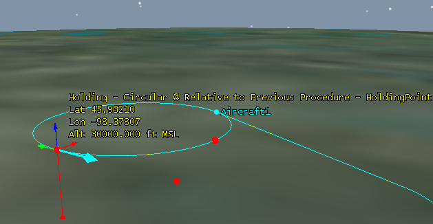
Figure 1 - The final control point of the mission, with none of the axes selected for modification.
To modify an element of the control point, click the appropriate arrow so that its color turns to yellow. The heading arrow remains light blue. Next click the control point and drag it to the desired position. To modify latitude and longitude at once, click each one in turn before clicking and dragging the control point. When you release the mouse button after moving the control point, the modified route is displayed in yellow.
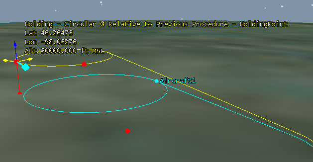
Figure 2 - The final control point of the mission after changing its latitude and longitude, with the modified route displayed in yellow.
Be aware that the altitude arrow as seen from the default, Earth Inertial Axes reference frame typically appears more like a point on top of the control point, rather than an arrow. This is because you are looking straight down, or nearly so, upon the arrow. From this view, the arrow still functions as the others do, but dragging the control point to the right reduces the altitude and dragging it to the left increases the altitude.
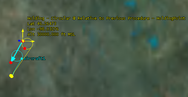
Figure 3 - The Earth Inertial Axes view.
Modifying the position of a control point will usually have an effect on the position of other control points, according to the relationships between them. Refer to the Help topic for the procedure that you are modifying to understand how the control points are connected to each other.
Additional Commands
Right-click on a procedure to access additional editing commands, as described in the following table.
Table - Additional Commands
| Command |
Description |
| Shift / Rotate Procedure... |
Opens the Shift / Rotate Procedures window. Use to move and rotate the selected procedure while maintaining the relative positioning of the other procedures in the mission. |
| Move Waypoints... |
Opens the Move Waypoints window. Use to change the latitude and longitude values of the selected procedure's site. |
| Switch Point to Point Procedure Type... |
If the currently selected procedure is a Point to Point procedure, select this command to change it to a different type of Point to Point procedure than the one currently defined. |
| Procedure Time Options |
Provides a sub-menu of four procedure time commands:
- Reset Mission Epoch. Sets the mission epoch to the recalculated start time of the first procedure; this option is unavailable if the first procedure has a fixed start time.
- Clear Interrupt Times. Removes the interrupt time, if one has been defined, so that the procedure will run to completion.
- Set Normal Duration. Defines the procedure duration as the natural product of the procedure's start and stop times.
- Set Auto Duration - enables the procedure duration to be adjusted by Aviator to satisfy the start of stop times of other procedures; this option disables the Set Interrupt Time property.
|
| Add Parallel Flight Line... |
Opens the Add Flight Lines window Use to insert a series of Parallel Flight Line procedures. |
| Export selected procedures as Mission... |
Opens the Export Flight Package window. Use to save the selected mission as a Flight Package. |
3D Editing Exceptions
There are several differences between editing missions in the 3D Graphics window and the Mission window.
Table - 3D Editing Exceptions
| Affected Property |
Description |
| Basic Point to Point Flight Path Angle |
If you select the altitude arrow at a control point, the heading arrow allows you to change the aircraft's flight path angle. If you select the longitude and latitude arrows, the heading arrow functions as it normally does for all procedures and allows you to change the aircraft's heading. |
| Wheels Release and Touchdown control points |
You cannot adjust the altitude of Wheels Release (for Takeoff procedures) or Touchdown (for Landing procedures) control points using 3D Editing.
|
| Default altitude |
The default altitude of a procedure inserted using 3D editing is defined as the altitude at the end of the previous procedure.
|
| Direct flight |
The aircraft flies directly to a new waypoint that has been inserted using 3D editing; it does not arrive on a heading for the next waypoint. |
| Holding procedures |
When you insert a holding procedure using 3D editing, the insertion point is defined as the holding point; the other procedure control points are positioned accordingly. |
| "Relative to Stationary STK Object" site |
When you an insert a procedure with a Relative to Stationary STK Object site, the waypoint is placed at the cursor's location and Aviator selects the nearest facility, place, or target object as the reference object. You can move the waypoint as normal after the initial placement. If you change the location of the reference object, the waypoint is moved accordingly and the mission recalculated. |
| STK Object Waypoint |
When you insert a procedure with an STK Object Waypoint site, the waypoint is placed at the location of the nearest supported STK object. The position of the waypoint cannot be modified by moving the control point; to move the waypoint, use the Site properties panel. |
Display of Invalid Procedures
If you create a procedure or modify a performance model such that it invalidates the mission, a warning message will appear on the screen, and the invalid procedure and each of the procedures after it will be surrounded by a red square with an X through it.