STK Premium (Air) or STK Enterprise
You can obtain the necessary licenses for this tutorial by contacting AGI Support at support@agi.com or 1-800-924-7244.
The results of the tutorial may vary depending on the user settings and data enabled (online operations, terrain server, dynamic Earth data, etc.). It is acceptable to have different results.
This lesson can be completed with or without an internet connection.
Capabilities covered
This lesson covers the following capabilities of the Ansys Systems Tool Kit® (STK®) digital mission engineering software:
- STK Pro
- Aviator
Problem statement
Engineers and operators require a way to model and simulate a takeoff and landing from an improvised airstrip. This mission planning is important in areas where formalized flight facilities don't exist.
Solution
Use the STK software's Aviator capability and the 3D Aviator Editing toolbar to model an aircraft's performance characteristics and to create a mission with a short takeoff from a cleared airstrip to an area of interest, a return to the airstrip, and a landing thereon.
What you will learn
Upon completion of this tutorial, you will understand the following:
- How to model a custom airstrip
- How to use the 3D Aviator Editing toolbar to perform 3D mission editing
Video guidance
Watch the following video. Then follow the steps below, which incorporate the systems and missions you work on (sample inputs provided).
Creating a new scenario
First, you must create a new scenario, and then build from there.
- Launch the STK application (
 ).
). - Click
 Create a Scenario when the Welcome to STK dialog box opens.
 - Enter the following in the STK: New Scenario Wizard:
- Click when you finish.
- Click Save (
 ) when the scenario loads.
 - Verify the scenario name and location in the Save As dialog box.
- Click .
| Option | Value |
|---|---|
| Name | STK_Aviator |
| Location | Default |
| Start | Default date and a time of 19:00:00.000 UTCG |
| Stop | + 2 hr |
The STK application creates a folder with the same name as your scenario for you.
Save (![]() ) often during this scenario!
) often during this scenario!
Configuring the 3D Graphics window
Configure the 3D Graphics window for better situational awareness for your airborne mission.
Turning on label declutter
Enable
- Bring the 3D Graphics window to the front.
- Click Properties (
 ) in the 3D Window Defaults toolbar.
 - Select the Details page when the Properties Browser opens.
- Select the Enable check box in the Label Declutter panel.
- Click to confirm your selection and to keep the Properties Browser open.
Displaying a compass
You can display a compass in the 3D Graphics window for situational awareness by updating the
- Select the Annotation page.
- Select the Show check box in the Compass panel.
- Enter 80 in the Radius field.
- Click to confirm your selections and to close the Properties Browser.
When you return to the 3D Graphics window, in the lower left corner of the window, there is a small compass.
Selecting the Hybrid Microsoft Bing map
If you have an Internet connection, change your imagery to use a Hybrid Microsoft Bing map. This provides better situational awareness. If you don't have an Internet connection, move on to the
- Click Microsoft Bing™ Maps (
 ) on the 3D Graphics window's Microsoft Bing™ Maps toolbar.
 - Select the Hybrid option in the drop-down menu.
- Click to confirm your selection.
Modeling an improvised airstrip
You are launching your airborne mission using a UAV from an improvised airstrip, one which cannot be loaded from the ARINC424 runways database (FAANFD18). A simple way to visualize a custom airstrip on top of the terrain or the WGS84 ellipsoid is by using an Area Target object. If you do not have an Internet connection or a satellite picture of the area, outlining it with an Area Target object is a good way to gain situational awareness of the airstrip's size and location.
Inserting an Area Target object
An
- Bring the Insert STK Objects (
 ) tool to the front.
 - Select Area Target (
 ) in the Select An Object To Be Inserted list.
 - Select Area Target Wizard (
 ) in the Select A Method list.
 - Click .
Outlining a desert airstrip
Use the
- Enter Airstrip in the Name field when the Area Target Wizard opens.
- Click four times.
- Enter the following four points in the order shown. You can copy and paste the individual values into the Area Target Wizard, if you are able.
- Click to confirm your changes and to close the Area Target Wizard.
| Latitude | Longitude |
|---|---|
| 34.0558 deg | -114.815 deg |
| 34.0671 deg | -114.799 deg |
| 34.0661 deg | -114.798 deg |
| 34.0549 deg | -114.814 deg |
Changing the airstrip's visualization properties
Make the airstrip easier to see in the 2D and 3D Graphics windows by updating the
- Right-click on Airstrip () in the Object Browser.
- Select Properties () in the shortcut menu.
- Select the 2D Graphics - Attributes page when the Properties Browser opens.
- Open the Line Width drop-down list.
- Select the heaviest line width.
- Click to confirm your selections and to close the Properties Browser.
Visualizing the airstrip in the 3D Graphics window
Zoom to the airstrip in the 3D Graphics window.
- Bring the 3D Graphics window to the front.
- Right-click on Airstrip () in the Object Browser.
- Select Zoom To in the shortcut menu.
- Use your mouse to obtain a good view of Airstrip ().
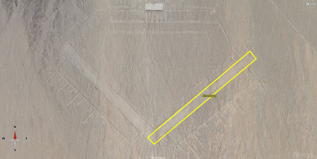
3D Graphics Airstrip View
Creating an entry point
After you take off, you will fly out and establish a circular flight pattern. Use a Place object to model an entry point to line up the circular flight pattern around a designated area of interest.
- Insert a Place (
 ) object using the Define Properties () method.
 - Select the Basic - Position page when the Properties Browser opens.
- Enter the following values in the Position Panel:
- Click to confirm your changes and to close the Properties Browser.
- Right-click on Place1 () in the Object Browser.
- Select Rename in the shortcut menu.
- Rename Place1 () EntryPoint.
| Option | Value |
|---|---|
| Latitude | 33.7795 deg |
| Longitude | -115.347 deg |
Inserting an Aircraft object
Add an
- Insert an Aircraft (
 ) object using the Insert Default () method.
 - Rename Aircraft1 () Test_UAV.
Changing the surface reference and animation mode
When you insert an Aircraft object into the STK application, change its propagator to Aviator, and apply the change, you will receive a Flight Path Warning message telling you, "For optimal performance of an Aviator aircraft in STK the Scenario globe surface reference should be set to MSL (mean sea level), and the Animation mode should be set to X Real Time." When you open the 3D Aviator Editing tool from the 3D Object toolbar, however, you won't receive this message. You can nevertheless make these selections manually prior to enabling the 3D Aviator Editing toolbar.
- Open STK_Aviator's () Properties ().
- Select the 3D Graphics - Global Attributes page when the Properties Browser opens.
- Open the Surface At drop-down list in the Surface Reference of Earth Globes panel.
- Select Mean Sea Level.
- Open the On Terrain drop-down list in the Surface Lines panel.
- Select On.
- Click to confirm your selections and to close the Properties Browser.
- Select X Real-time Animation Mode (
 ) in the Animation toolbar.
Selecting On displays surface lines on terrain data whenever it is available from any source.
Enabling the 3D Aviator Editing toolbar
The 3D Aviator Editing toolbar provides convenient access to Aviator commands. The concepts are the same as using the
Displaying the 3D Aviator Editing toolbar
Before you can access and use the 3D Aviator Editing toolbar, you must first select it in the View menu.
- Select the View menu in the Menu Bar.
- Select Toolbars in the shortcut menu.
- Select 3D Aviator Editing in the sub menu.
![]()
3D Aviator Editing Toolbar
Switching to the 3D Aviator Editing toolbar
Use the 3D Object Editor to define and modify the position of your aircraft in the 3D Graphics window. This is required to use 3D Aviator Editing toolbar.
- In the 3D Editing Object toolbar, open the drop-down list.
- Select Aircraft/Test_UAV.
- Click Object Edit Start/Accept (
 ) to start the 3D Object Editing tool.
 - Click Switch to Aviator (
 ) on the 3D Aviator Editing toolbar.
 - Read the warning that the operation can't be undone.
- Click to continue.
You can also open the 3D Aviator Editing toolbar on the aircraft's Basic - Route properties page by first changing the propagator to Aviator, then clicking in the Mission window.
Selecting the aircraft model
An
- Click Select Aircraft (
 ) in the 3D Aviator Editing toolbar.
 - Right-click on Basic UAV (
 ) in the User Aircraft Models (
 ) list when the Select Aircraft dialog box pens.
 - Select Duplicate in the shortcut menu.
- Right-click on Basic UAV Copy ().
- Select rename in the shortcut menu.
- Rename Basic UAV Copy () Test UAV Desert.
- Select Test UAV Desert ().
- Click to confirm your changes and to close the Select Aircraft dialog box.
Note that Basic UAV (![]() ) is marked read only (
) is marked read only (![]() ). To make any modifications, you must first duplicate the model.
). To make any modifications, you must first duplicate the model.
Selecting the aircraft's performance models
- Click Aircraft Catalog for Current Aircraft (
 ).
). - Select Acceleration () Built-In Model (
 ) in the Performance Models list when the Test UAV Desert dialog box opens.
 - Select the Aerodynamics tab.
- Open the Strategy drop-down list.
- Select HighFast.
- Read the warning when then AeroProp Warning dialog box opens.
- Click to continue.
- Click .
- Click to confirm your selection and to close the Test UAV Desert dialog box.
The HighFast aerodynamics strategy must be paired with its HighFast propulsion model counterpart.
The High Fast aerodynamics strategy uses thrust to generate a lift vector, which provides the ability to track fuel burn during lift. Additionally, it generates the forces perpendicular to the velocity vector to provide maneuvering. The High Fast propulsion strategy provides propulsive force, which overcomes drag and provides the force to accelerate. You'll use the rest of the default values for this simulation.
Taking off from the airstrip
Your UAV is taking off from the improvised airstrip. You can define this using a Takeoff procedure executed at a Runway site. A Procedure defines an action that the aircraft executes. Each procedure is associated with a Site. A Site defines the location (excluding altitude) of the procedure and the types of procedures that are available to select. The exact relationship between the site location and the procedure is dependent on the specific procedure.
Orienting the view in the 3D Graphics window
Before attempting to create a Takeoff procedure, orient the 3D Graphics window so that the top of the window points north and you are looking straight down on the airstrip. This will make it easier to place the aircraft correctly for its takeoff roll.
- Zoom in to Airstrip () in the 3D Graphics window.
- Click Orient North (
 ) in the 3D Graphics window toolbar.
 - Click Orient from Top (
 ).
).
Choosing the site
In the 3D Aviator Editing toolbar, there are two drop-down lists. The first one, Aviator Site, defaults to Waypoint. You will change it to Runway. In Aviator, a Runway is a ground-based location. When you select the Runway site type, specific details of the runway location must be defined manually.
- Return to the 3D Aviator Editing toolbar.
- Open the Aviator Site drop-down list.
- Select Runway.
Choosing a procedure
The second drop-down list, Aviator Procedure, defaults to Basic Point to Point. You will change it to Takeoff. A
- Open the Aviator Procedure drop-down list.
- Select Takeoff.
Creating the Takeoff procedure
You want to begin your Takeoff procedure at the southwest end of the airstrip. The
- Using the mouse, Shift + click on Airstrip's centroid.
- Scroll out far enough to see one red ball at each end of the Takeoff procedure.
- Click on the Takeoff @ Runway - WheelsRelease red ball, which will likely be west of and closest to the Airstrip's centroid.
- Click and drag the red ball to the runway threshold, centering it in the middle of the airstrip.
- Click Object Edit Start/Accept (
 ) in the 3D Object Editing toolbar.
This is near where the Airstrip label is located.
The runway threshold is the south-west end of the airstrip. This will be the wheels release point.
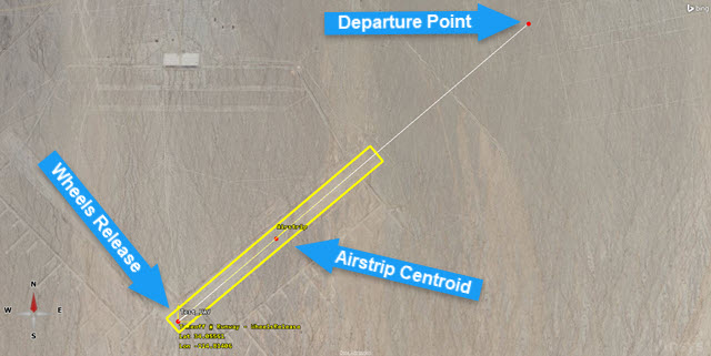
Takeoff procedure
Viewing the UAV in the 3D Graphics window
It's a good idea to check the placement of your aircraft on the runway and if the Takeoff procedure is lined up correctly.
- Right-click on Test_UAV () in the Object Browser.
- Select Zoom To in the shortcut menu.
You may notice that the aircraft is floating well above the terrain; adjust its placement so that it's sitting closer to the earth's surface.
Modifying the aircraft's placement on the runway
Have the UAV follow the terrain during its takeoff roll. Furthermore, compensate for the placement of the 3D model's wheels to ensure that they visually appear to be on the runway.
- Click Object Edit Start/Accept () to start the 3D Object Editing tool.
- Click Modify Procedure (
 ) in the 3D Aviator Editing toolbar.
 - Select the Use headwind runway option in the Runway Heading The direction that the aircraft is pointing. panel when the Takeoff Properties dialog box opens.
- Enter 5 ft in the Runway Altitude Offset field.
- Select the Use Terrain for Runway Altitude check box.
- Click to confirm your changes and to close the Takeoff Properties dialog box.
- Click Object Edit Start/Accept () to confirm your changes.
This will use terrain data to define the runway's ground-level altitude.
Viewing the Takeoff procedure in the 3D Graphics window
You can view the Takeoff procedure in the 3D Graphics window and make any adjustments that you find necessary.
- Bring the 3D Graphics window to the front.
- Zoom to Test_UAV ().
- Look at the 3D Graphics model to make sure it's above the surface of the terrain, and the alignment of the UAV's takeoff roll is within the boundaries of the airstrip.
- If required, use the 3D Object Editing tool and the 3D Aviator Editing tool to continue to adjust the Takeoff procedure until you are satisfied with Test_UAV's () alignment with the airstrip.
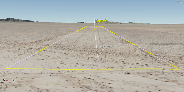
Proper Alignment
Saving the improvised airstrip to a catalog
Once you are satisfied with the Takeoff procedure, save the runway to a
- Click Object Edit Start/Accept () to start the 3D Object Editing tool.
- Click Modify Site (
 ) in the 3D Aviator Editing toolbar.
 - Enter Airstrip in the Name field when the Runway Properties dialog box opens.
- Click .
- Click to close the Add Successful dialog box.
- Click to close the Runway Properties dialog box.
- Click Object Edit Start/Accept () to confirm your changes.
Creating a circular holding flight pattern
After taking off, the UAV will fly to an area of interest, around which it will orbit in a circular holding pattern.
Using the STK Static object to create a circular holding pattern
Earlier, you created an entry point. Select an
- Zoom to EntryPoint ().
- Click Object Edit Start/Accept () to start the 3D Object Editing tool.
- Open the Aviator Site drop-down list.
- Select STK Static Object.
- Open the Aviator Procedure drop-down list.
- Select Holding - Circular.
- Shift + click on EntryPoint () in the 3D Graphics window.
- Click Object Edit Start/Accept () to confirm your changes.
This will place the holding point above EntryPoint. The holding point for the procedure is the point at which the aircraft enters and exits the holding circle and is the reference point for procedures that are set to end on a course to the next procedure. This holding point is defined by a bearing and range from the procedure site; the holding circle will be tangent to this line of bearing from the site. The site of a holding procedure is only a reference point for the holding pattern, and may not be encompassed by the aircraft's flight path.
Establishing a circular holding pattern around an area of interest
Once established, you need to modify the holding pattern to circle an area of interest. For this simulation, you want to circle Desert Center Airport.
- Zoom out in the 3D Graphics window so that you can see the holding circular holding pattern.
- Click Object Edit Start/Accept () to start the 3D Object Editing tool.
- Click Next Procedure (
 ) in the 3D Aviator Editing toolbar so that the quarter circle point is highlighted in the 3D Graphics window.
 - Click Modify Site () in the 3D Aviator Editing toolbar.
- Select EntryPoint () in the Link To list when the STK Static Object Properties dialog box opens.
- Click to confirm you selection and to close the STK Static Object Properties dialog box.
- Click Modify Procedure () in the 3D Aviator Editing toolbar.
- Set the following parameters in the Hold Options panel when the Holding - Circular Properties dialog box opens:
- Click to confirm your changes and to close the Holding - Circular Properties dialog box.
- Click Object Edit Start/Accept () to confirm your changes.
The quarter circle point is placed one quarter of the distance along the pattern's perimeter in the direction that the aircraft will fly as part of pattern.
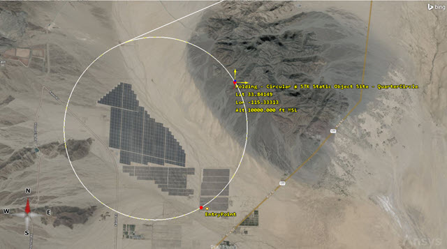
Highlighted Holding Circular pattern
| Option | Value |
|---|---|
| Bearing | 235 deg |
| Range | 0 nm |
| Diameter | 4 nm |
| Use Alternate Entry Points | Cleared |
| Turn Direction | Outbound Left Turn |
| Number of Full Turns | 4 |
Viewing the circular holding patter in the 3D Graphics window
You can view the circular holding pattern in the 3D Graphics window. If you are creating your own simulation in a different area, you will need to modify the procedure until you place your holding pattern in the correct location.
- Bring the 3D Graphics window to the front.
- Zoom to EntryPoint ().
- Use your mouse to zoom out until you can see the circular holding pattern around Desert Center Airport.
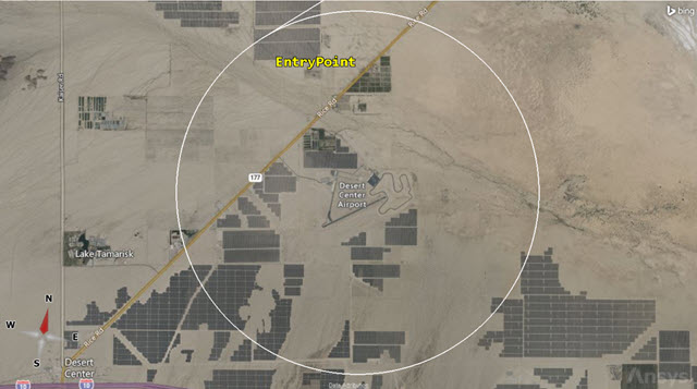
Circular holding pattern
Landing back at the improvised airstrip
After circling Desert Center Airport, the UAV will return to the airstrip and land.
Setting up for the next procedure
Use the 3D Aviator Editing toolbar to add a procedure subsequent to the currently selected procedure.
- Click Object Edit Start/Accept () to start the 3D Object Editing tool.
- Click Next Procedure () in the 3D Aviator Editing toolbar so that the holding circular point is highlighted in the 3D Graphics window.
- Zoom to Airstrip ().
Using the Runway from Catalog site and a Landing procedure
Set Aviator Site to use
- Open the Aviator Site drop-down list.
- Select Runway from Catalog.
- Open the Aviator Procedure drop-down list.
- Select Landing.
Selecting the airstrip for the Landing procedure
Select the runway that you added to the catalog and modify the Landing procedure.
- Shift + click on Airstrip's () centroid.
- Click Modify Procedure () in the 3D Aviator Editing toolbar.
- Select the Use headwind runway option in the Runway Heading panel when the Landing Properties dialog box opens.
- Enter 5 ft in the Runway Altitude Offset field in the Landing Options panel.
- Select the Use Terrain for Runway Altitude check box in the Landing Options panel.
- Select the Delay Enroute Climbs and Descents check box in the Enroute Options panel.
- Click to confirm your changes and to close the Landing Properties dialog box.
- Click Object Edit Start/Accept () to confirm your changes.
Looking a warnings in the Message Viewer
The STK application uses the Message Viewer window to display error messages, warning messages, and informational messages. Currently, there is a warning (![]() ) in Message Viewer.
) in Message Viewer.
- Open the View menu.
- Select Message Viewer.
- Expand the Message Viewer as necessary.
- Look at the latest messages.
- At the bottom of the Message Viewer, you'll see a tab named All Messages.
- Right-click on the All Messages tab.
- Select Clear All Tabs in the shortcut menu.
- Close (
 ) the Message Viewer window.
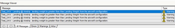
Message Viewer Warning
The warnings show that the maximum landing weight for the aircraft is greater than allowed.
Configuring the UAV's fuel load
From the Message Viewer, you learned that the UAV has exceeded its max landing weight. While one option could be to put in some additional flight time to burn off the excess fuel, a better way is to calculate the amount of fuel needed and to adjust the initial amount of fuel accordingly.
Determining the maximum landing weight
Determine the UAV's maximum landing weight by viewing its
- Open Test_UAV's () Properties ().
- Select the Basic - Route page when the Properties Browser opens.
- Click Configuration (
 ) in the Initial Aircraft Setup toolbar.
 - Select the Basic tab when the Aircraft Configuration dialog box opens.
- Look at the Max Landing Weight value.
- Select the Fuel tab.
- Click to close the Aircraft Configuration dialog box.
The maximum allowed landing weight of your aircraft is 3000 pounds.
The initial fuel state at takeoff is 2000 pounds of fuel.
Viewing profile data
You can use the Report & Graph Manager to create reports and graphs for the simulation. However, a quicker way to obtain information on the mission is to use the
- Right-click on Landing (
 ) in the Mission Profile.
 - Select Profile Data at Final State ... in the shortcut menu.
- Scroll through the data displayed when the Landing dialog box opens.
- Look at Fuel Consumed.
- Look at Fuel State.
- Scroll down to Weight.
- Fuel Consumed: approximately 336 pounds
- Fuel State: approximately 1,664 pounds
- Weight: approximately 3,664 pounds
- Close () the Landing dialog box.
Fuel consumed is the amount of fuel it took to fly the mission
Fuel state is the amount of fuel remaining in the fuel tank at the end of the mission.
This is the weight of the aircraft at the end of the mission.
Tutorial weights:
Looking at the above values, you can easily remove fuel from the initial state to drop the landing weight below 3000 pounds while still ensuring there is extra fuel remaining when the aircraft lands.
Your weights might be different than the weights in this tutorial, but they should be close if you've followed the steps in the tutorial. Any differences are most likely due to where you placed your wheels release point for your Takeoff procedure.
Adjusting the initial fuel state
Remove the unneeded fuel by adjusting the initial fuel state of the aircraft.
- Click Configuration () in the Initial Aircraft Setup toolbar.
- Select the Stations tab when the Aircraft Configuration dialog box opens.
- Select Internal Fuel (
 ).
). - Enter 1000 lb in the Initial state field.
- Click .
- Click to close the Aircraft Configuration dialog box.
- Click to confirm your changes and to keep the Properties Browser open.
Reviewing the changes
Confirm the new quantities with the Profile Data.
- Right-click on Landing () in the mission profile.
- Select Profile Data at Final State ... in the shortcut menu.
- Look at Fuel State and Weight when the Landing dialog box opens.
- Close () the Landing dialog box.
On landing, the aircraft should still have over 600 pounds of fuel and it should now be under the maximum landing weight of 3,000 pounds.
Display dynamic data in the 3D Graphics window
Add a dynamic
- Select the 3D Graphics - Data Display page.
- Click .
- Select Flight Profile by Time in the Styles list when the Add a Data Display dialog box opens.
- Click to confirm your selection and to close the Add a Data Display dialog box.
- Click to confirm your changes and to close the Properties Browser.
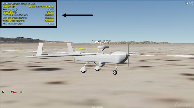
flight profile by time data display
Animating the scenario
You can now animate the scenario.
- Bring the 3D Graphics window to the front.
- Zoom to Test_UAV ().
- Click Reset (
 ) in the Animation toolbar.
 - Click the Start (
 ) to animate the scenario.
 - Click Reset () when finished.
Saving your work
Close out your scenario.
- Save () your work.
- Close the scenario when finished.
Summary
You were introduced to the 3D Aviator Editing toolbar, which allowed you to mission plan an aircraft flight route using the 3D Editing Object tool and the 3D Graphics window. You planned a flight route for a UAV taking off from an improvised desert airstrip, establishing a circular holding pattern over an area of interest and landing back at the airstrip. You determined that you needed to remove excess fuel due to the aircraft being overweight during landing. After removing fuel, you determined that you had enough fuel to fly the mission and land with an acceptable fuel reserve.