EOIR General Vehicle Shape Properties
For STK's EOIR capability, you can set image generation properties for the selected STK objects (not missiles) as described in this topic. First, you must include the object as a target in an EOIR configuration. Then when you can open the object's properties, you will see EOIR Shape as an option under the Basic properties. The following sections describe the parameters you can specify for the object.
Shape
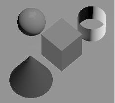
Specify one of the following shape options:
- Select from one of the simple geometrics: Box, Cone, Coupler (cone frustum), Cylinder, Plate, or Sphere
- None removes it from the geometric and radiometric calculations while retaining its position and orientation calculations. It is often convenient to assign the parent object to which a sensor is attached as shape None. Since a sensor cannot image its parent object, this speeds up radiometric calculation with little or no effect on the results.
- Select one of the composite shapes constructed from one or more of the simple geometrics or other composite shapes at specified offsets and orientations with respect to one another:
- GeoComm, based on the 3D model anik_f1.glb
- LeoComm, based on the 3D model iridium.glb
- LeoImaging, based on the 3D model quickbird2.glb
The models are in the STK install folder <Install Dir>/STKData/VO/Models/Space.
- CustomMesh loads an external model (*.obj) file that defines a custom model. The sample_custom_mesh.obj file loads by default. To select a different file, click the ellipsis. For information on converting a model file to an OBJ file, see Converting 3D Models to OBJ Files for Rendering in EOIR. When a custom mesh object becomes smaller than a pixel,
- PointSourceSignature loads an external Target Signature file (*.tsf) that defines the EOIR properties with a target signature that can vary with time, angle, and wavelength. For information on the file format, click Target Signature file (.tsf).
When an object of one material becomes smaller than a pixel, EOIR will approximate it as follows:
- For simple geometric shapes and custom meshes, EOIR uses an analytical approximation. The calculations for custom meshes occur at a five-degree viewing angle from the center, to keep the computation time from becoming excessive.
- For compound objects consisting of two or more simple geometric shapes, EOIR will approximate each shape as a bounded sphere while estimating the percentage overlap for high-accuracy areas.
Dimensions
You can specify the dimensions (e.g., Height, Radius, Width, Depth, and Max Dimension) of a simple geometric shape.
Material specification
Designate the material properties of your target:
Single Material. Apply a single material to all surfaces of a target model. Select the single material item in the Material Elements box to display its editable properties, including temperature and material.
Geometric Groups. Apply two or more unique material properties based on the geometric groups of the target model. When you select this option, the geometric groups for the target model will appear in the Material Elements box. Select an item in the Material Elements box to specify its editable properties, including temperature and material.
The Material Element box lists the components for the target model for which you can specify materials properties. When you select an item from the list in the Material Elements box, you can then specify its editable properties, including temperature and material.
When an object with two or more materials becomes smaller than a pixel, EOIR will approximate it as a bounded sphere of one material. This can adversely affect calculations. AGI recommends using a point source signature file for this situation.
Body Temperature
For the Body Temperature, click the shortcut menu to choose one of the following options:
| Option | Description |
|---|---|
| Static | STK applies this temperature to the entire shape. This then applies for the entire EOIR scene time period. |
| Time Profile | Loads a time-temperature profile (.tpf) file. The sample_time_profile.tpf file loads by default. To select a different file, click the ellipsis. To create a TPF external file, see TPF data file format. |
| Data Provider | When you select this option, and additional shortcut menu called Temperature Data appears. Click the Temperature Data shortcut menu to choose a temperature parameter from data providers for the object (aircraft, satellite, etc.). If no temperature parameters from data providers are available, the shortcut menu will be gray, so you must then choose a different Body Temperature option. |
Surface material
This is the material type that appears on the surface of the entire shape. You can select either one of the materials in the dropdown menu or a custom material.
The Custom Material option enables you to load an external Spectral Response Function (*.srf) file that defines custom materials. This file models operationally relevant materials and accurately characterizes their desired spectral response function. The sample_material_profile.srf file loads by default. To select a different file, click the ellipsis. To create an SRF external file, see SRF data file format.
Each Surface Material has optical properties used in the sensor scene calculation. One of these is reflectance. Light bouncing off a surface is selectively reflected by wavelength; i.e., some wavelengths are absorbed instead of reflected. In the visible wavelengths, this is what gives objects color. Each Surface Material has a table of its Reflectance versus Wavelength.
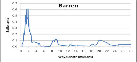
One particular material, Gray Body, has a user-selectable reflectance that is constant across the spectrum. It does not represent any real material but is useful for setting up test situations.
For more information on material models, see Material Types Modeled in EOIR.
Reflectance
The Reflectance can vary from no light reflected (0 %) to all light reflected (100 %).