Sensor Definition
The Definition page enables you to set parameters defining a sensor's field of view.
| Sensor Type | Description |
|---|---|
| Complex Conic | Defined by specified inner and outer half angles and minimum and maximum clock angles. |
| Custom | Import a custom sensor pattern file. |
| EOIR | Models electro-optical and infrared sensors. |
| Half Power | Models a parabolic antenna. |
| Rectangular | Specify vertical and horizontal half-angles that will be used to model the field of view of an instrument. |
| SAR | Synthesizes the aperture of a larger antenna than is actually present, using SAR pattern definitions designed to model the field of regard of a SAR sensor onto the surface of the earth. |
| Simple Conic | Defined by a specified cone half angle. |
- If you are not licensed for a given sensor type, it will appear dimmed in the sensor type shortcut menu. Find out more on the licensing Help page.
- In the absence of terrain, a sensor on a vehicle will use either a reference ellipsoid if it is above it or a scaled ellipsoid that passes through its current location if it is below the reference ellipsoid. This ensures that the sensor projection appears even if the sensor is below the reference ellipsoid, as can be the case, for example, when a ship is placed at zero MSL altitude.
Complex Conic sensor patterns
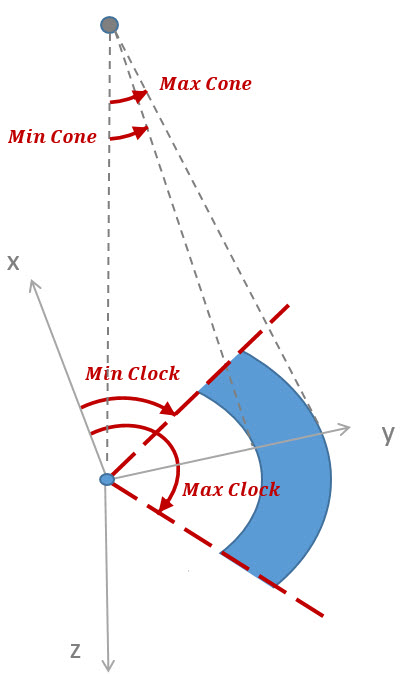
Complex Conic sensor patterns are defined by the inner and outer half angles and minimum and maximum clock angles of the sensor's cone.
Half Angles
Use Inner and Outer Half Angles to define the angular radius of the cone measured from the boresight. When an inner cone is specified as greater than zero, the inner region (the unshaded cone in the illustration below) is considered to be a region of exclusion.
Clock Angles
Use Minimum and Maximum Clock Angles to define the range of rotation about the boresight relative to the up vector. The clock angles correspond to azimuth angles, which are defined in the sensor pointing direction. The angles are positive in a right-handed sense about the boresight vector for satellites and aircraft (see illustration below). For facilities and targets, the angles are positive in a left-handed sense about the boresight vector.
Specification of a zero inner half angle and clock angles spanning 360 degrees results in a sensor field of view pattern equivalent to a simple conic pattern.
Figure 1. Complex Sensor Angles![]()
Custom sensor patterns
The Custom sensor type enables you to create and import your own sensor pattern files. You can:
- Create and edit custom sensor patterns manually for sensors attached to all types of parent objects
- Use the pattern tool if your sensor is attached to a vehicle
It is important to use an adequate number of points in the sensor pattern file in order to obtain expected results. This recommendation is based on that fact that a number of different methods of interpolating between specified nodes in the pattern are used for different applications within the software. For example, lines connecting nodes for the purpose of displaying the sensor pattern in 2D or 3D windows are generated in a different space than what is used for interpolation between sensor pattern nodes during access computations. These differences can result in misleading graphical representations of the field of view which are inconsistent with computed access intervals. The best way to minimize such discrepancies is to specify a finer granularity in the sensor pattern. For most applications, a spacing between sensor pattern nodes of 3 degrees or less is adequate to support accurate computations and consistent visualization.
It is possible to define the boresight of a sensor that isn't in the sensor's field of view. If you target a sensor with a boresight defined outside of the sensor's field of view, the sensor may appear to be targeting incorrectly. This is because the sensor targets along the boresight.
Use the  button in the Custom area to browse for a pattern file (*.pattern), then click OK or Apply in the Definition page to load the new sensor pattern.
Half Power Sensor Patterns
Half Power sensor patterns are designed to model parabolic antennas.
| Value | Description |
|---|---|
| Frequency (GHz) | Specify the antenna's frequency in GigaHertz. |
| Diameter | Specify the diameter of the antenna dish. |
| Half Angle | Based on the values entered for Frequency and Diameter, STK calculates the half angle of the cone for you. The result appears after you click Apply on the Definition page. |
The Frequency value is always expressed in GHz, regardless of the frequency unit set at the scenario level.
The two-sided beamwidth of a Half Power sensor is calculated as follows:
where  is equal to the wavelength (m), which is equal to the speed of light (m/sec) divided by the frequency (Hz), and D is equal to the diameter of the transmit antenna (m). The coefficient of illumination is assumed to be 70.0 degrees, which represents nonuniform illumination. A coefficient of 58.5 degrees would represent uniform illumination. The beamwidth is divided by 2 to provide the effective half-angle.
Rectangular Sensor Patterns
Rectangular sensor types are typically used with satellites or aircraft for modeling the field of view of instruments such as push broom sensors and star trackers. Rectangular sensors are defined according to specified vertical and horizontal half-angles.
The vertical and horizontal half-angles used in the specification of rectangular sensors serve to define the sensor field of view as being constrained by four planes intersecting at the vertex of the sensor. The resulting sensor pattern provides a rectangular shape when projected to a plane perpendicular to the boresight direction. This pattern does not, however, provide a rectangular shape when projected to the surface of a circumscribing sphere or onto a surface of a planet. Deviations from the defined rectangular shape during projection are amplified as the amount of curvature in the projection surface is increased within the field of view of the sensor. For example, a small rectangular sensor pattern projected to the ground from low altitude will largely remain rectangular in appearance due to the surface being essentially flat while a larger sensor pattern projected from higher altitude will appear to bow out at the corners.
To create a sensor field of view that projects as a rectangle on the surface of a circumscribing sphere, you can use a complex conic sensor with inner and outer cone right angles centered around 90 degrees. For example, to generate such a sensor with a 20-degree width, you would specify inner and outer cone angles of 80 and 100 degrees. You would use the minimum and maximum clock angles to restrict the complimentary extent of the field of view.
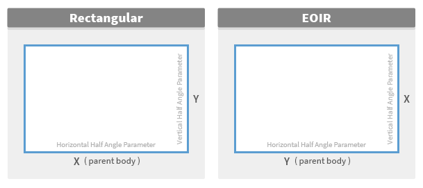
The naming convention for the parameters used to specify the shape of a rectangular sensor assumes that the satellite to which the sensor is attached is geostationary with its X axis in the direction of the ECI velocity vector and its Z axis pointed toward nadir. The following diagram is a view looking down the boresight of a rectangular sensor and illustrates the two possible coordinate systems:
Figure 3. Rectangular Sensor Coordinate Systems![]()
SAR sensor patterns
The Synthetic Aperture Radar (SAR) sensor type is designed to model the field of regard of a SAR sensor with respect to the surface of the Earth. A SAR sensor pattern synthesizes the aperture of a larger antenna than is actually present. Special signal processing that integrates data from multiple images collected over time generates a high-resolution image of the target.
Defining a SAR sensor requires that you specify elevation angles, exclusion angles, and the altitude of the parent object.
| Option | Description |
|---|---|
| Elevation Angles | These are the minimum and maximum ground elevation angles to which the SAR sensor can provide coverage. |
| Exclusion Angles | These are the minimum angle between the forward and aft projections of the velocity vector and the vector to the target. |
| Track Parent Altitude | If enabled, the SAR sensor tracks the altitude of the parent object, rather than assuming a constant altitude. |
SAR pattern definition
This pattern definition is appropriate only for a sensor with a parent object located at some constant altitude above the surface (such as a satellite or an aircraft). The definition of the field of regard also relies on the velocity of the parent object in the Earth-centered fixed coordinate system. This fact places an implicit requirement on the parent object that the attitude of the parent object be defined with its X-axis along the Earth-fixed velocity vector (as is the case with the default attitudes for satellites and aircraft). SAR sensors should be pointed at nadir.
Field of regard
The field of regard of the SAR sensor is constructed as a combination of the following four cones:
Elevation angles
Define the inner exclusion cone and outer inclusion cone by specifying the Minimum (outer cone) and Maximum (inner cone) ground Elevation Angles, where the SAR sensor can provide coverage at the parent object's altitude.
Figure 4. Structure of the SAR Field![]()
Exclusion angles
Define forward and aft exclusion cones with Forward and Aft Exclusion Angles. These exclusion angles represent the minimum angle between the forward or aft projection of the Earth-fixed velocity vector of the parent and the vector from the parent object to the target object. These exclusion angles are related to the maximum Doppler shift under which the SAR sensor can operate.
Figure 5. Structure of SAR Exclusion Zones![]()
The effect of forward and aft exclusion cones is that they take "bites" out of the outer inclusion cone, which is defined by the minimum elevation angle. The pattern that is then projected to the plane is illustrated in the following diagram:
Figure 6. Projected SAR Sensor Pattern![]()
Simple Conic sensor patterns
A Simple Conic sensor pattern is defined by a simple cone angle, such as that shown in the illustration below. To define the simple cone, enter the Cone Half Angle.