STK Premium (Space) or STK Enterprise
You can obtain the necessary licenses for this tutorial by contacting AGI Support at support@agi.com or 1-800-924-7244.
The results of the tutorial may vary depending on the user settings and data enabled (online operations, terrain server, dynamic Earth data, etc.). It is acceptable to have different results.
This tutorial requires version 12.8 of the STK software or newer to complete in its entirety.
Capabilities covered
This lesson covers the following capabilities of the Ansys Systems Tool Kit® (STK®) digital mission engineering software:
- STK Pro
- Coverage
- STK SatPro
Problem statement
Engineers want to design a constellation of satellites that will provide imaging over the contiguous United States (CONUS). The imaging satellites will not have on-board storage; they must transmit near-real-time imagery to a ground station. In order for the satellites to send their imagery to the ground station, they must either use a direct connection to the ground station or an indirect connection to it through a constellation of relay satellites. You require a quick and easy way to model the coverage provided by both methods, taking into account connections between the imaging satellites, the relay satellites, and the ground station.
Solution
Use the STK SatPro capability to design a constellation of imaging satellites and a constellation of relay satellites. Use Chain objects together with the STK software's Coverage capability to determine the percentage of the U.S mainland that can be observed over the course of one day: first when using a direct connection between the imaging satellites and the ground station, then with an indirect connection from the imagining satellites to the ground station through the constellation of relay satellites.
What you will learn
Upon completion of this tutorial, you will understand the following:
- How to use Chains with the Coverage capability
- How to insert a Satellite Collection object
- How to use the Walker tool
Creating a new scenario
First, you must create a new scenario, then build from there.
- Launch the STK application (
 ).
). - Click
 Create a Scenario in the Welcome to STK dialog box.
 - Enter the following in the STK: New Scenario Wizard:
- Click when you finish.
- Click Save (
 ) when the scenario loads. The STK application creates a folder with the same name as your scenario for you.
 - Verify the scenario name and location in the Save As dialog box.
- Click .
| Option | Value |
|---|---|
| Name | Chains_Coverage |
| Location | Default |
| Start | 15 Jun 2023 16:00:00.000 UTCG |
| Stop | + 24 hrs |
Save (![]() ) often during this lesson!
) often during this lesson!
Disabling steaming terrain
Analytical and visual terrain is not required in this analysis. Turn off the Terrain Server.
- Right-click on Chains_Coverage () in the Object Browser.
- Select Properties (
 ).
). - Select the Basic - Terrain page in the Properties Browser.
- Clear the Use terrain server for analysis check box.
- Click to accept the change and to close the Properties Browser.
Modeling the ground site
Use the default Facility object to simulate the location of the ground site that will receive data from the satellites.
- Bring the Insert STK Objects (
 ) tool to the front.
 - Insert a Facility (
 ) object using the Insert Default () method.
 - Right-click on Facility1 () in the Object Browser.
- Select Rename in the shortcut menu.
- Rename Facility1 () Ground_Site.
Creating a Walker satellite constellation
A
Creating a seed satellite
The original satellite that is used to create the Walker constellation is referred to as the "seed" satellite and the satellites generated using the Walker tool are the children. When you create a Walker constellation, the tool will duplicate the original (seed) satellite as part of the constellation. The new satellites will be the children of the seed. Use the Orbit Wizard to create the seed satellite, from which the other satellites will be derived.
- Insert a Satellite (
 ) object using the Orbit Wizard (
 ) method.
 - Click .
- Set the following options in the Orbit Wizard:
- Click to propagate Imager () and close the Orbit Wizard.
| Option | Value |
|---|---|
| Type | Circular |
| Satellite Name | Imager |
Creating the seed satellite's imaging camera
If the seed satellite has sub-objects such as sensors, the Walker tool will create the same sub-objects for each of the child satellites. Use a Sensor object to simulate the field of view of your seed satellite's imaging camera, which will then be used for the other satellites in the Walker constellation.
- Insert a Sensor (
 ) object using the Insert Default () method.
 - Select Imager () in the Select Object dialog box.
- Click .
- Rename Sensor1 () Camera.
- Open Camera's () Properties ().
- Enter 10 deg in the Simple Conic - Cone Half Angle field.
- Click .
Creating a Walker constellation from the seed satellite
You have defined a satellite with the characteristics and orbit you need. Now, use the Walker tool to model the constellation of imaging satellites. For your imaging satellite constellation, one satellite in each of six orbital planes is required.
- Insert a Satellite Collection (
 ) object using the Walker tool () method.
 - Click when the Walker tool opens.
- Select Imager () in the Select Object dialog box.
- Click to close the Select Object dialog box.
- Set the following values:
- Set the following Container Options:
- Click .
- Click to close the Walker tool.
- Clear the check box for Imager () in the Object Browser.
| Option | Value |
|---|---|
| Number of Sats per Plane | 1 |
| Number of Planes | 6 |
| Option | Value |
|---|---|
| Create new Satellite Collection | Selected |
| Name | Imager_Satellites |
This turns the seed satellite off visually in both the 2D and 3D Graphics windows, but it's still available analytically.
Creating a Chain object
A Chain object models a list of objects — individual, grouped into constellations, and satellite collections — in order of access. Access enables you to determine the times one object can see another object. Create a Chain object that represents the direct connection from the imaging satellites to the ground site.
Inserting a Chain object
Insert a new Chain object.
- Insert a Chain (
 ) object using the Insert Default () method.
 - Rename Chain1 () Direct_Connection.
Defining the Chain's Start and End objects
By defining a Start object, an End object, and a set of object connection pairs, the STK application can compute times when one object can see another through connections to one or more other objects. Start by choosing the start object — the ground site — and end object — the imaging satellites' sensors — in your Chain.
- Open Direct_Connection's () Properties ().
- Select the Basic - Definition page.
- Click the Start Object ellipsis (
 ).
). - Select Ground_Site () in the Select Object dialog box.
- Click to close the Select Object dialog box.
- Click the End Object ellipsis ().
- Select AllSensors (
 ) in the Select Object dialog box.
 - Click to close the Select Object dialog box.
AllSensors (![]() ) is an automatically generated
) is an automatically generated
Choosing the Chain's first connection
After you choose the start and end objects in your Chain, you need to build the Chain's connections. The first connection is from the ground site to the imaging satellites.
- Click in the Connections panel.
- Click the From Object ellipsis ().
- Select Ground_Site () in the Select Object dialog box.
- Click to close the Select Object dialog box.
- Click the To Object ellipsis ().
- Select the AllSatellites () subset in Imager_Satellites () in the Select Object dialog box.
- Click to close the Select Object dialog box.
For all Satellite Collection objects, the STK application automatically generates a subset named AllSatellites that contains all members of the collection.
Choosing the Chain's second connection
Now choose the second connection. The second connection is from the imaging satellites to the imaging satellites' sensors.
- Select the first connection in the Connections list.
- Click .
- Ensure Imager_Satellites/AllSatellites is selected for the From Object.
- Click the To Object ellipsis ().
- Select AllSensors () in Imager_Satellites () in the Select Object dialog box.
- Click to close the Select Object dialog box.
- Click to accept your changes and close the Properties Browser.
Evaluating coverage with a direct connection
The STK software's
Targeting the contiguous United States
An Area Target object models a region on the surface of a central body. In this case, you are focusing your analysis inside CONUS.
- Insert an Area Target (
 ) object using the Select Countries and US States (
 ) method.
 - Select United_States_of_America in the list in the Select Countries And US States dialog box.
- Click .
- Click to close the Select Countries And US States dialog box.
- Zoom In (
 ) to the United_States_of_America () in the 2D and 3D Graphics windows if you desire.
Area targets used to define custom regions should have a longitude span no greater than 180 degrees. This limitation includes area targets encompassing a polar region.
Inserting a coverage definition
A Coverage Definition object enables you to define and maintain an area of coverage, to define the STK objects providing coverage for the area (such as satellites, aircraft and sensors), to define the time period of interest, and to calculate accesses to the region.
- Insert a Coverage Definition (
 ) object using the Insert Default () method.
 - Rename CoverageDefinition1 () US_Cov.
Defining the coverage grid
The statistical data computed during a coverage analysis is based on a set of locations, or points, which spans your geographical area of interest. For analysis purposes, you can further refine your geographical area of interest using regions and points. Regions are closed boundaries that contain points. Points have specific geographical locations, and the STK application computes accessibility to a region based on the accessibility to the points within that region. The combination of the geographical area, the regions within that area, and the points within each region is called the
- Open US_Cov's () Properties ().
- Select the Basic - Grid page.
- Open the Type drop-down list.
- Select Custom Regions.
- Open the Area Of Interest drop-down list.
- Select Area Targets.
- Move (
 ) United_States_of_America () from the Area Targets list to the Selected Regions list.
 - Click to accept your changes and keep the Properties Browser open.
Setting the point granularity
When using custom regions for your point grid definition, it is important to select an adequate
- Enter 1 deg in the Point Granularity - Lat/Lon field.
- Click .
Assigning the Chain as your coverage asset
The Coverage Definition object's Assets properties enable you to specify the STK objects used to provide coverage. Available asset classes are facilities, targets, all types of vehicles, sensors, constellations, satellite collection subsets — and Chains. Assign the Direct_Conection Chain object as your Coverage Asset.
- Select the Basic - Assets page.
- Select Direct_Connection () in the Assets list.
- Click .
- Click to accept your changes and to close the Properties Browser.
- Look at your 2D and 3D Graphics windows. Your coverage grid is displaying in both windows.
Computing accesses
The ultimate goal of coverage is to analyze accesses to an area using assigned assets and applying necessary limitations upon those accesses. Compute coverage for US_Cov with the Compute Accesses tool.
- Select US_Cov () in the Object Browser.
- Select the CoverageDefinition menu.
- Select Compute Accesses.
Evaluating the quality of coverage with a Figure Of Merit
You can evaluate the quality of coverage for an area by attaching Figure Of Merit objects the Coverage Definition object. The default
- Bring the Insert STK Objects () tool to the front.
- Insert a Figure Of Merit (
 ) using the Insert Default () method.
 - Select US_Cov () when the Select Object dialog box opens.
- Click .
- Rename FigureOfMerit1 () Simple_Cov.
- Look at the 2D and 3D Graphics windows.
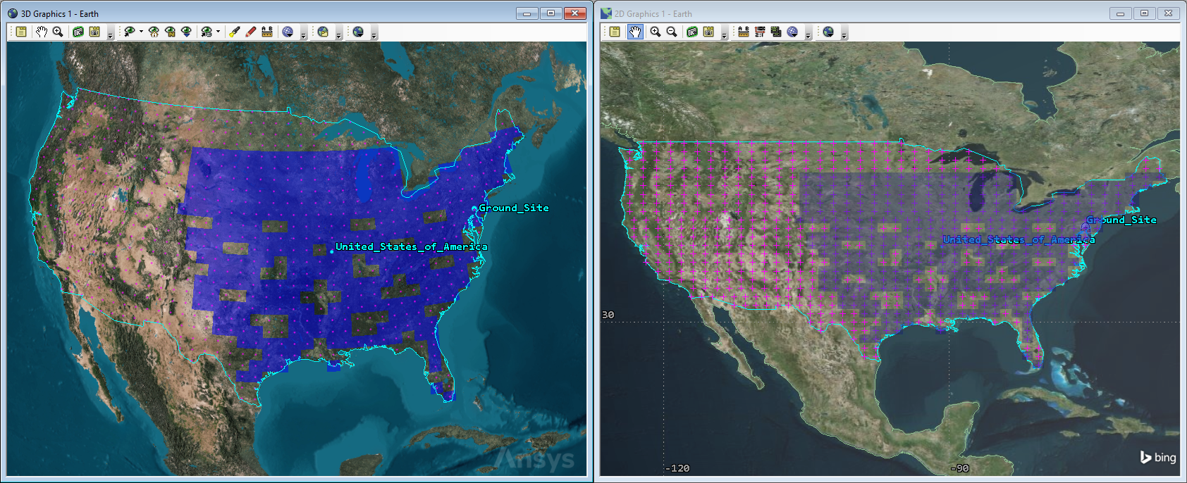
Direct Simple Coverage
You can see from looking at the 2D and 3D Graphics windows that you don't have 100% coverage.
Determining the percentage satisfaction
Beyond just visualizing coverage, the Coverage capability also enables you to generate textual reports detailing global and regional coverage statistics as well as Figure of Merit statistics. You are interested in Simple Coverage and the percentage of coverage over the contiguous United States. The Static Satisfaction data provider and the Percent Satisfied data provider element provides the data your require.
- Right-click on Simple_Cov () in the Object Browser.
- Select Report & Graph Manager... (
 ) in the shortcut menu.
 - Select the Percent Satisfied (
 ) report in the Installed Styles (
 ) folder when the Report & Graph Manager opens.
 - Click .
- Scroll to the bottom of the report.
- Review the data in the FOM Properties section.
- Close (
 ) the Percent Satisfied report when finished.
 - Close () the Report & Graph Manager when finished.
Dy downloading data directly through the imaging satellites to the ground site, you are able to cover almost 3.7 million square kilometers, or approximately 46%, of the U.S. mainland.
Evaluating coverage through an indirect connection
Now that you know what the baseline coverage of your imaging satellite constellation is when the satellites have a direct connection to your ground site, determine the percentage satisfaction when the satellites can pass near-real-time data to the ground site through a relay satellite. Set up a new Chain object that passes the data from the imaging satellites to the ground site by way of any available relays in another constellation of satellites.
Creating a seed satellite for the relay constellation
Use the Orbit Wizard to create the seed satellite, from which you will derive a new Walker constellation of relay satellites
- Insert a Satellite () object using the Orbit Wizard () method.
- Set the following options in the Orbit Wizard:
- Click to propagate Relay () and to close the Orbit Wizard.
| Option | Value |
|---|---|
| Type | Circular |
| Satellite Name | Relay |
| Inclination | 60 deg |
| Altitude | 2000 km |
Creating a Walker constellation of relay satellites
Use the Satellite Collection object and the Walker tool to generate a new Walker constellation. For your preliminary analysis, one satellite in six orbital planes are required.
- Insert a SatelliteCollection () object using the Walker tool () method.
- Click when the Walker tool opens.
- Select Relay () in the Select Object dialog box.
- Click to close the Select Object dialog box.
- Set the following values:
- Set the following Container Options:
- Click .
- Click to close the Walker tool.
- Clear the check box for Relay () in the Object Browser.
| Option | Value |
|---|---|
| Number of Sats per Plane | 1 |
| Number of Planes | 6 |
| Option | Value |
|---|---|
| Create Satellite Collection | Selected |
| Name | Relay_Satellites |
Inserting another Chain object
Insert another Chain object to model the connections in your relay system.
- Insert a Chain () object using the Insert Default () method.
- Rename Chain2 () Indirect_Connection.
Defining the Chain's start and end objects
As before, start by choosing the start object (the ground site) and end object (the imaging satellites' sensors) in your Chain.
- Open Indirect_Connection's () Properties ().
- Select the Basic - Definition page.
- Click the Start Object ellipsis ().
- Select Ground_Site () in the Select Object dialog box.
- Click to close the Select Object dialog box.
- Click the End Object ellipsis ().
- Select AllSensors () in Imager_Satellites () in the Select Object dialog box.
- Click to close the Select Object dialog box.
Choosing the Chain's first connection
After you choose the start and end objects in your Chain, you need to build the Chain's connections. The first connection is from the ground site to the relay satellites.
- Click in the Connections panel.
- Click the From Object ellipsis ().
- Select Ground_Site () in the Select Object dialog box.
- Click to close the Select Object dialog box.
- Click the To Object ellipsis ().
- Select AllSatellites () in Relay_Satellites () in the Select Object dialog box.
- Click to close the Select Object dialog box.
Choosing the Chain's second connection
Next, choose the second connection. The second connection is from the relay satellites to the imaging satellites.
- Select the first connection in the Connections list.
- Click .
- Ensure Relay_Satellites/AllSatellites is selected for the From Object.
- Click the To Object ellipsis ().
- Select AllSatellites () in Imager_Satellites () in the Select Object dialog box.
- Click to close the Select Object dialog box.
Choosing the Chain's third connection
Now choose the third connection. The third connection is from the imaging satellites to the their sensors.
- Select the second connection in the Connections list.
- Click .
- Ensure Image_Satellites/AllSatellites is selected for the From Object.
- Click the To Object ellipsis ().
- Select AllSensors () in Imager_Satellites () in the Select Object dialog box.
- Click to close the Select Object dialog box.
- Click to accept your changes and to close the Properties Browser.
Changing coverage assets
You previously computed coverage using the Direct_Connection Chain object and determined that approximately 45% of the Contiguous United States could be seen by your imaging cameras when downloading the data directly to the ground site. Now, determine the percentage of coverage when transmitting the data through the constellation of relay satellites.
- Open US_Cov's () Properties ().
- Select the Basic - Assets page.
- Select *Direct_Connection (Active) () in the Assets list.
- Click .
- Select Indirect_Connection () in the Assets list.
- Click .
- Click . The STK application will automatically recompute coverage.
- Look at the 2D and 3D Graphics windows.
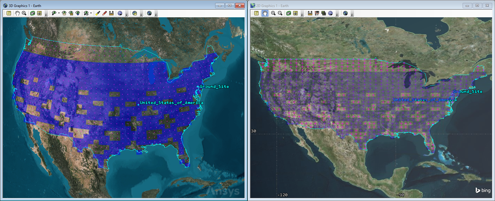
Indirect Simple Coverage
Visually you can see that while you don't have 100% satisfaction, coverage has improved. But by how much?
Determining Indirect Coverage Percent Satisfied
Using only a direct connection between the imaging satellites and the ground site gives you approximately 46% of coverage over the Continental United States. Using the relay satellites, how much improvement do you get?
- Right-click on Simple_Cov () in the Object Browser.
- Select Report & Graph Manager... () in the shortcut menu.
- Select the Percent Satisfied () report in the Installed Styles list.
- Click .
- Scroll to the bottom of the report.
- Review the data in the FOM Properties section.
By transmitting data to a relay satellite and then to the ground site, you are able to cover over 5.7 million square kilometers, or nearly 72%, of the contiguous United States.
Saving your work
Clean up and close out your scenario.
- Close any open reports, properties, and the Report & Graph Manager.
- Save () your work.
Summary
Your first analysis was based on a direct connection between the imaging satellites and the ground site. In order to download the data, the camera passes the data to the parent satellite, which must have access to the ground site at the same time. You set this up using a Chain object. Using a Coverage Definition object and assigning the Direct_Connection Chain object as the asset, you determined through Simple Coverage that using the direct connection provided approximately coverage over approximately 46% of the contiguous United States.
Your second analysis was based on an indirect connection between the imaging satellites and the ground station. In this analysis, you set up a Chain object that passed the data from the imaging satellites to any of the Relay satellites that had access at the same time with the ground station. Changing your assigned asset to the Indirect_Connect Chain object improved your coverage to nearly 72% — a 56% increase of the area of the U.S. mainland covered.