STK Pro, STK Premium (Air), STK Premium (Space), or STK Enterprise
You can obtain the necessary licenses for this tutorial by contacting AGI Support at support@agi.com or 1-800-924-7244.
This lesson requires an internet connection to complete in its entirety.
The results of the tutorial may vary depending on the user settings and data enabled (online operations, terrain server, dynamic Earth data, etc.). It is acceptable to have different results.
Capabilities covered
This lesson covers the following capabilities of the Ansys Systems Tool Kit® (STK®) digital mission engineering software:
- STK Pro
- Communications
- Radar
Problem statement
Engineers and operators need to quickly model and analyze a telemetry link from a missile launch and to determine how various settings on a radar will affect its ability to track a missile. You are launching a test missile from a launch pad located on the Pacific Coast of the United States. The missile will transmit telemetry data to a communications system on board a ship anchored off the coast. The missile's telemetry data will be transmitted on an S-band frequency, which is close to a frequency used by multiple high-power satellite digital audio radio service (SDARS) satellites. Phase one of your test will determine if the satellites, which provide XM radio service, will interfere with ship's ability to receive the test missile telemetry data. Phase two of your test will determine for how long a shipborne radar system can detect and track the missile during its flight. A custom radar cross section and a radar antenna pattern file are required for your analysis.
Solution
Use the STK software's Communications capability to perform a preliminary analysis of both tests. Model the communication systems on the missile and the ship, compute a link budget, and determine if the SDARS transmitters interfere with received telemetry data. If there is interference, use a spectrum filter to accurately model the power transfer from the interference source to the receiver. Using the Radar capability, model the ship's radar system that will track the missile. Use external radar cross section and antenna pattern files in the analysis to add realism to your model.
What you will learn
Upon completion of this tutorial, you will be able to:
- Model and analyze communications interference in a radio frequency (RF) receiver
- Use a Butterworth filter to mitigate communications interference
- Insert an external radar antenna pattern
- Use an external radar cross section file for radar analysis
Creating a new scenario
First, you must create a new scenario, then build from there.
- Launch the STK application (
 ).
). - Click
 Create a Scenario in the Welcome to STK dialog box.
 - Enter the following in the STK: New Scenario Wizard:
- Click when you finish.
- Click Save (
 ) when the scenario loads.
 - Verify the scenario name and location when the Save As dialog box opens.
- Click .
| Option | Value |
|---|---|
| Name | CommRadar_MissileTest_Interference |
| Location | Default |
| Start | Use the default date / set the time to 16:00.00.000 UTCG |
| Stop | + 35 min |
A folder with the same name as your scenario is created for you.
Save (![]() ) often during this lesson!
) often during this lesson!
Disabling streaming terrain
By default, the STK application connects to the Ansys Geospatial Data Cloud to distribute Earth terrain data for analysis and visualization. Turn off
- Right-click on CommRadar_MissileTest_Interference () in the Object Browser.
- Select Properties (
 ) in the shortcut menu.
 - Select the Basic - Terrain page when the Properties Browser opens.
- Clear the Use terrain server for analysis check box in the Terrain Server panel.
- Click to confirm your change and to close the Properties Browser.
Modeling the test missile
Your missile will launch from Vandenberg Space Force Base in California and will ditch in the ocean in the Western Range upon completion of the test.
Inserting a new Missile object
Insert a new Missile object into your scenario. A
- Bring the Insert STK Objects tool (
 ) to the front.
 - Select Missile (
 ) in the Select An Object To Be Inserted list.
 - Select Define Properties () in the Select A Method list.
- Click .
Designing the Missile object's trajectory
The
- Select the Basic - Trajectory page when the Properties Browser opens.
- Notice that the default Propagator is Ballistic.
- Set the following options:
- Click to confirm your changes and to close the Properties Browser.
- Right-click on Missile1 () in the Object Browser.
- Select Rename in the shortcut menu.
- Rename Missile1 () Test_Missile.
| Option | Value |
|---|---|
| Launch Latitude - Geodetic | 34.7556 deg |
| Launch Longitude | -120.6223 deg |
| Launch Altitude | 8 ft |
| Fixed Delta-V | Default (6.90194 km/sec) |
| Impact Latitude - Geodetic | 10 deg |
| Impact Longitude | 173 deg |
| Impact Altitude | 8 ft |
Viewing the test missile
View the test missile in the 3D Graphics window.
- Bring the 3D Graphics window to the front.
- Right-click on Test_Missile () in the Object Browser.
- Select Zoom To in the shortcut menu.
- Move around in the 3D Graphics window to get a better view of Test_Missile ().
- Click Decrease Time Step (
 ) in the Animation toolbar, and set the Time Step to 1.00 sec.
 - Click Start (
 ) to animate the scenario.
 - Watch as Test_Missile () travels along its path.
- Click Reset (
 ) when finished.
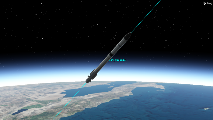
Test Missile in Flight
Generating an Altitude vs Ground Range report
You can determine the missile's flight time and other pertinent information using the Report & Graph Manager. There are a few reports that will provide the flight time, but each report will provide different data concerning the missile itself. To keep it simple, generate an
- Right-click on Test_Missile () in the Object Browser.
- Select Report & Graph Manager... (
 ) in the shortcut menu.
 - Select the Altitude vs Ground Range (
 ) report style, located in the Installed Styles (
 ) folder in the Styles panel list, when the Report & Graph Manager opens.
 - Click .
- Scroll through the report.
- Note that Test_Missile () will impact the ocean at the end of its arc, approximately 32 minutes after launch.
- When you are finished, close the Altitude vs Ground Range report.
- Click to close the Report & Graph Manager.
Modeling the test missile's transmitter
A transmitter on Test_Missile will send telemetry data to the ship.
Inserting a Transmitter object
Attach a Transmitter object to Test_Missile. A
- Bring the Insert STK Objects tool () to the front.
- Insert a Transmitter (
 ) object using the Insert Default () method.
 - Select Test_Missile () when the Select Object dialog box opens.
- Click to confirm your selection and to close the Select Object dialog box.
- Rename Transmitter1 () Missile_Tx.
Using a Medium Transmitter model
A
- Open Missile_Tx's () Properties ().
- Select the Basic - Definition page when the Properties Browser opens.
- Click the Transmitter Model Component Selector (
 ).
). - Select Medium Transmitter Model (
 ) in the Transmitter Models list when the Select Component dialog box opens.
 - Click to confirm your selection and to close the Select Component dialog box.
- Select the Model Specs tab.
- Set the following transmitter specifications:
- Click to confirm your changes and to keep the Properties Browser open.
| Option | Value |
|---|---|
| Frequency | 2.31 GHz |
| Power | 80 W |
| Gain | -0.57 dB |
| Data Rate | 2.048 Mb/Sec |
Setting the transmitter modulation options
The STK application features a number built-in common analytical
- Select the Modulator tab.
- Leave the Modulator type set to BPSK.
- Select the Use Signal PSD check box.
- Click to confirm your selection and to close the Properties Browser.
The PSD is used to determine the Bandwidth Overlap Factor. By using signal PSD, you combine the entire signal including losses in your analysis. The nulls are where the main lobe and side lobes drop to zero. If this option is not selected, the PSD will be modeled as a flat spectrum with unity magnitude across the transmitter's bandwidth.
Modeling the ship
The ship is anchored off the coast of California. It will function as the test location for your communications and radar equipment.
Inserting a new Ship object
Insert a
- Bring the Insert STK Objects tool () to the front.
- Insert a Ship object (
 ) using the Insert Default () method.
 - Rename Ship1 () Ship.
Defining the ship's route options
- Open Ship's () Properties ().
- Select the Basic - Route page when the Properties Browser opens.
- Use the default GreatArc propagator.
- Open the Route Calculation Method drop-down list.
- Select Specify Time.
- Open the Reference drop-down list in the Altitude Reference panel.
- Select WGS84.
The ship will remain stationary for the duration of your scenario. Specify Time uses the Time properties of each waypoint.
Since you've disabled analytical terrain, you want the ship to sit on the surface of the WGS84 ellipsoid.
Defining the ship's waypoints
Now, add the waypoints for the ship's route. The ship will remain stationary, so you can define a route using two waypoints set at the same location over the course of your analysis period.
- Click .
- Set the following options for the first waypoint:
- Click again.
- Set the second waypoint's time to be 35 minutes from the first point's time (for example, [Date] 16:35:00.000 UTCG).
- Click to confirm your changes and to close the Properties Browser.
| Option | Value |
|---|---|
| Latitude | 34.196 deg |
| Longitude | -120 deg |
You want to be sure the ship remains stationary for the duration of your analysis period.
Inserting a Sensor object
A Sensor object can be used to model a servo motor to steer an antenna, be it an Antenna object or an analytical antenna embedded in another communications object. In this instance, it will act as the ship's RF receiver antenna's steering motor. The receiver will accept Missile_Tx's incoming telemetry transmissions.
- Bring the Insert STK Objects tool () to the front.
- Insert a Sensor (
 ) object using the Insert Default () method.
 - Select Ship () when the Select Object dialog box opens.
- Click to confirm your selection and to close the Select Object dialog box.
- Rename Sensor1 () Antenna_Motor.
Defining the sensor's cone half angle
Antenna_Motor's field of view is not being used for anything other than situational awareness. In order to see it, but to keep it from obstructing other views in the 3D Graphics window, minimize its cone half-angle by updating the sensor's
- Open Antenna_Motor's () Properties ().
- Select the Basic - Definition page when the Properties Browser opens.
- Enter 5 deg in the Cone Half Angle field in the Simple Conic panel.
- Click to confirm your change and to keep the Properties Browser open.
Setting the antenna motor's location
Update the sensor's
- Select the Basic - Location page.
- Open the Location Type drop-down list.
- Select Fixed.
- Set the following options:
- Click to confirm your changes and to keep the Properties Browser open.
With this option, the location of the sensor is defined using a fixed displacement vector with respect to the parent object’s body frame.
| Option | Value |
|---|---|
| X | 75 ft |
| Z | 75 ft |
Targeting the test missile
Next, target the test missile by updating the sensor's
- Select the Basic - Pointing page.
- Open the Pointing Type drop-down list.
- Select Targeted.
- Use the Default Receive Track mode in the Targeted panel.
- Select Test_Missile () in the Available Targets list.
- Move (
 ) Test_Missile () to the Assigned Targets list.
 - Click to confirm your changes and to close the Properties Browser.
The Track Mode specifies how you want to orient the antenna. By default, this is set to Receive; this orients the antenna slightly "behind" the current location of the other object. The STK application computes the appropriate amount by which to lead or trail based on the light time delay. Access computations including the computation of targeting times are performed based on the sensor being the receiver of the signal.
Viewing the targeted antenna in the 3D Graphics window
View the ship and its sensor in the 3D Graphics window.
- Zoom To Ship ().
- Click Start () on the Animation toolbar to animate the scenario.
- Look at Antenna_Motor's () location on the ship.
- Click Reset () when you are finished.
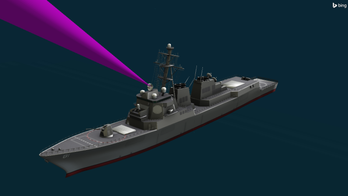
Sensor Targeting Test Missile
When Antenna_Motor is able to access Test_Missile, the sensor field of view will be visible.
Modeling the test ship's receiver
The ship's on-board communications equipment will receive telemetry transmissions from the missile.
Inserting a Receiver object
Use a Receiver object to model the characteristics of the receiver, the antenna it uses, and the environment in which it operates.
- Bring the Insert STK Objects tool () to the front.
- Insert a Receiver (
 ) object using the Insert Default () method.
 - Select Antenna_Motor () when the Select Object dialog box opens.
- Click to confirm your selection and to close the Select Object dialog box.
- Rename Receiver1 () Ship_Rx.
Using a Complex Receiver model
Use a
- Open Ship_Rx's () Properties ().
- Select the Basic - Definition page when the Properties Browser opens.
- Click the Receiver Model Component Selector ().
- Select Complex Receiver Model () in the Receiver Models list when the Select Component dialog box opens.
- Click to confirm your selection and to close the Select Component dialog box.
- Leave the Auto Track check box selected.
- Click to confirm your changes and to keep the Properties Browser open.
The Auto Track option allows a receiver to track and lock onto the transmitter's carrier frequency with which it is currently linking, including any Doppler shift.
Defining the receiver's antenna specifications
The receiver uses a Helix antenna pattern, which models a standard helical antenna.
- Select the Antenna tab.
- Select the Model Specs sub-tab.
- Click the Antenna Model Component Selector ().
- Select Helix () in the Antenna Models list when the Select Component dialog box opens.
- Click to confirm your selection and to close the Select Component dialog box.
- Set the following antenna specifications:
- Click to confirm your changes and to keep the Properties Browser open.
| Option | Value |
|---|---|
| Design Frequency | 2.5 GHz |
| Diameter | 0.9 m |
| Turn Spacing | 1 mm |
| Number of Turns | 3 |
Visualizing the receiver's antenna pattern
The
- Select the 3D Graphics - Attributes page.
- Select the Show Volume check box in the Volume Graphics panel.
- Enter 0.5 km in the Gain Scale (per dB) field.
- Select the Set Azimuth and elevation resolution together check box in the Patten panel.
- Enter 1 deg in the Resolution field in the Azimuth panel.
Adding gain coloring
Use the Explicit Levels Method to define individual antenna gain levels and specify how colors will be added to show antenna gain.
- Open the Method drop-down list in the Gain Coloring panel.
- Select Explicit Levels.
- Select the Relative to Maximum check box in the Gain Coloring panel.
- Set the following options in the Level Adding panel:
- Click .
- Click to confirm your changes and to keep the Properties Browser open.
When selected, the antenna gain level values are assumed to be relative to the maximum value.
| Option | Value |
|---|---|
| Add Method | Start, Stop, Step |
| Start | -70 |
| Stop | 0 |
| Step | 10 |
Viewing the antenna pattern in the 3D Graphics window
With your gain antenna graphics configured, view the pattern in the 3D Graphics window.
- Bring the 3D Graphics Window to the front.
- Click Start () on the Animation toolbar to animate the scenario.
- Click Reset () when you are finished.
- Return to Ship_Rx's () Properties ().
- Clear the Show Volume check box in the Volume Graphics panel.
- Click to confirm your change and to close the Properties Browser.
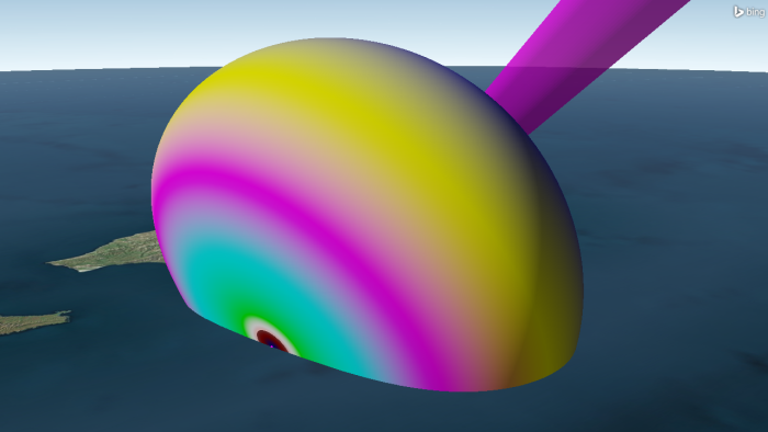
Helix Antenna Pattern
When Antenna_Motor accesses Test_Missile, the antenna pattern will be visible.
Analyzing the telemetry downlink's link budget
The missile will transmit telemetry data to the ship during its flight. Create a simple link budget to calculate the bit error rate (BER), which reflects of how often errors occur in the transmission of digital data. You can compute a simple link budget using the
- Right-click on Ship_Rx () in the Object Browser.
- Select Access... (
 ) in the shortcut menu.
 - Expand (
 ) Test_Missile () in the Associated Objects List when the Access tool opens.
 - Select Missile_Tx ().
- Click
 .
. - Click in the Reports panel.
- Scroll to the right until you find the BER column when the Link Budget report opens.
- Scroll down through the column.
- When finished, close the Link Budget report.
- Keep the Access tool open.
For the most part, you have good reception from the missile to the ship. As the missile gets further away from the ship, the bit error rate increases.
Inserting the interfering satellites
Recall that the missile is transmitting in the S band. This is near a frequency on which multiple SDARS satellites are providing XM satellite radio service. Insert the operational XM radio SDARS satellites
- Bring the Insert STK Objects tool () to the front.
- Insert a Satellite (
 ) object using the From Standard Object Database (
 ) method.
 - Clear the Data Sources: Local check box when the Search Standard Object Data dialog box opens.
- Enter SXM in the Name or ID field.
- Open the Owner drop-down list.
- Select United States.
- Click .
- Select all SXM satellites whose Operational Status is Operational in the Results list.
- Click .
- When all the Satellite () objects have propagated, click to close the Search Standard Object Data dialog box.
Modeling the interfering satellites' transmitters
The satellites broadcast XM radio in the S band. Model one satellite's transmitter first, then reuse it with for the other satellites so you don't have to model each individually.
Inserting a new Transmitter object
Attach a transmitter to one of the SXM satellites.
- Bring the Insert STK Objects tool () to the front.
- Insert a Transmitter () object using the Insert Default () method.
- Select one of the SXM Satellite (
 ) objects when the Select Object dialog box opens.
 - Click to confirm your selection and to Select Object dialog box.
Using a Medium Transmitter model
As with the missile's transmitter, use a Medium Transmitter model in your analysis.
- Open Transmitter2's () Properties ().
- Select the Basic - Definition page when the Properties Browser opens.
- Click the Transmitter Model Component Selector ().
- Select Medium Transmitter Model () in the Transmitter Models list when the Select Component dialog box opens.
- Click to confirm your selection and to close the Select Component dialog box.
- Select the Model Specs tab.
- Set the following transmitter specifications:
- Click to confirm your changes and to keep the Properties Browser open.
| Option | Value |
|---|---|
| Frequency | 2.3347 GHz |
| Power | 13300 W |
| Gain | 40 dB |
| Data Rate | 0.048 Mb/Sec |
Updating the modulation options
The satellite transmitters use quadrature phase shift keying (QPSK) to cover large regions with low population densities.
- Select the Modulator tab.
- Open the Name drop-down list.
- Select QPSK.
- Select the Use Signal PSD check box.
- Click to confirm your selections and to close the Properties Browser.
Reusing and renaming the satellite transmitters
All the SXM satellites will use the same transmitter type and specifications. You can reuse Transmitter2 (copy and paste) which is a quick way to create a new object having identical properties to an object already existing in the scenario.
- Select Transmitter2 () in the Object Browser.
- Click Copy (
 ) on the Object Browser toolbar.
 - Select another SXM satellite () in the Object Browser.
- Click Paste (
 ) on the Object Browser toolbar.
 - Repeat the process for the remaining SXM Satellites.
- Rename the transmitters [Satellite Common Name]_Tx.
For example, for the satellite SXM-10_64290 (![]() ), rename its transmitter SXM-10_Tx (
), rename its transmitter SXM-10_Tx (![]() ).
).
Checking for interference
There are several methods through which you can determine the impact of interference on a system. For more complex systems, you can use a
Adding interference sources to the receiver
Add the satellite transmitters as interference sources to your RF receiver through its properties. Then, you can assess their impact on the performance of the receiver.
- Open Ship_Rx's () Properties ().
- Select the Basic - Definition page when the Properties Browser opens.
- Select the Interference tab.
- Select the Use check box.
- Select Transmitter () in the Selection Filter panel.
- Move () all of the transmitters from the Available Emitters list to the Assigned Emitters list.
- Select Test_Missile/Mssile_Tx () in the Assigned Emitters list.
- Remove (
 ) Test_Missile/Mssile_Tx () from the Assigned Emitters list.
 - Click to confirm your changes and to keep the Properties Browser open.
Only qualified assets will appear in the Available Emitters list, including Transmitter objects configured with one of the RF transmitter models (no laser models) and Radar objects configured with either the Monostatic or Bistatic Transmitter Radar systems.
Determining the impact of interference with a Link Budget - Interference report
Generate a
- Return to the Access tool.
- Click .
- Select the Link Budget - Interference () report style, located in the Installed Styles () folder in the Styles panel list, when the Report & Graph Manager opens.
- Click .
- Click when the report opens.
- Enter 1 sec in the Step field.
- Select the Enter key.
- Locate the BER and BER+I columns.
- Scroll down through the report and compare the columns.
- Leave the Link Budget - Interference report open.
BER+I is the Bit Error Rate in the presence of Interference.
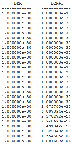
Link Budget - Interference report
Mitigating interference with a spectrum filter
Having determined that the SDARS satellites will interfere with the ship's receiver, you can apply a
Using a Butterworth filter
Use a Butterworth filter. A Butterworth filter has a flat passband and has a moderately steep roll off. It will suppress anything that falls outside of the passband. Ideally, you would like to filter out any satellite interference under five (5) MHz. However, this can be adjusted, if required.
- Return to Ship_Rx's () Properties ().
- Select the Filter tab.
- Select the Use check box in the Filter Model panel.
- Ensure Butterworth is selected for the Filter Model.
- Enter 5 MHz in the Cut-off Frequency field.
- Click to confirm your changes and to close the Properties Browser.
Recomputing the Link Budget - Interference report
Check the effect of filtering on the signal quality.
- Bring the Link Budget - Interference report the front.
- Click Refresh (F5) (
 ) in the report's toolbar.
 - Review the report.
- When finished, close the Link Budget - Interference report.
- Click to close the Report & Graph Manager.
- Clear the check box for Antenna_Motor () in the Object Browser.
- Bring the Access tool to the front.
- Click Remove All Accesses (
 ).
). - Click to close the Access tool.
- Save () your scenario.
Notice that BER+I using filtering shows improvement in link performance over BER+I without filtering. You should also see approximately 0.5 dB of improvement in the energy per bit to noise-plus-interference ratio (Eb/(No + Io)) with the Butterworth filter. Using a Butterworth filter, the ship can receive the missile's transmissions a few minutes longer. You could further tweak the values but this would be based on acceptable changes to your bandwidth.
This will remove it visually from your scenario.
Modeling the ship's radar
The second phase of the test determines for how long the ship's radar can track the test missile. The radar tracks the missile by sending pulses to determine probability of detection (PDET). The radar continues to send pulses until it meets an assigned signal-to-noise ratio (SNR) goal. At the end of sending the pulses, if none of them hit the missile and return, then the radar did not detect the missile.
The Radar capability implements a Swerling detection model. The probability of detection is a function of the per pulse SNR, the number of pulses integrated, the probability of false alarm, and the radar cross-section (RCS) fluctuation type, which is taken from the target RCS properties. You will base test on achieving an integrated PDET value of 0.800000 or higher, 1.000000 being the highest value.
Inserting a Radar object
A
- Bring the Insert STK Objects tool () to the front.
- Insert a Radar (
 ) object using the Insert Default () method.
 - Select Ship () when the Select Object dialog box opens.
- Click to confirm your selection and to close the Select Object dialog box.
- Rename Radar1 () Ship_Radar.
Setting the radar's mode
The ship is equipped with a
- Open Ship_Radar's () Properties ().
- Select the Basic - Definition page when the Properties Browser opens.
- Leave the Radar System set to Monostatic.
- Select the Mode tab.
- Ensure the Radar Monostatic Mode is set to Search Track.
- Select the Waveform sub-tab.
- Leave the Waveform set to Fixed PRF.
- Select the Pulse Definition sub-tab on the Waveform sub-tab.
- Enter 880 nsec in the Pulse Width field.
- Click to confirm your changes and to keep the Properties Browser open.
A
The waveform in your system will use a fixed pulse repetition frequency (PRF). The PRF is the number of pulses of a repeating signal in a specific time unit. After producing a brief transmission pulse, the transmitter turns off in order for the receiver to hear the reflections of that signal off of targets.
This is the width of the transmitted pulse in nanoseconds, which is equivalent to 8.8e-07 sec.
Setting the goal signal-to-noise ratio
Radar systems often use multiple pulse integration, which is the process of summing all the radar pulses, to improve detection. This helps increase the SNR. For a Fixed PRF radar, select either an integration analysis based on the desired signal-to-noise ratio (Goal SNR) or a fixed number of pulses (Fixed Pulse Number).
- Select the Pulse Integration sub-tab on the Waveform sub-tab.
- Leave the analysis mode set to Goal SNR.
- Enter 20 dB in the SNR field.
- Leave the Maximum Pulses set to the default value of 512.
- Click to confirm your changes and to keep the Properties Browser open.
Configuring the radar's antenna
The ship's tracking radar is similar to an airport surveillance radar, which spins, covering a 360-degree field of view. Model the radar's antenna with an
- Select the Antenna tab.
- Select the Model Specs sub-tab.
- Click the Antenna Model Component Selector ().
- Select External Antenna Pattern () when the Select Component dialog box opens.
- Click to confirm your selection and to close the Select Component dialog box.
- Enter 2.8 GHz in the Design Frequency field.
Selecting the external pattern file
Use an external antenna pattern file, which contains user-defined data, to model the field of view of this type of radar.
- Click the External Filename ellipsis ().
- Browse to <Install Dir>\Data\Resources\stktraining\samples when the Select File dialog box opens.
- Select ASR9Low.pattern.
- Click to select the antenna pattern file and to close the Select File dialog box.
- Click to confirm your changes and to keep the Properties Browser open.
The ASR9Low.pattern file uses a Symmetric antenna pattern format. You can open ASR9Low.pattern using a text editor such as Notepad to view the file. Use this type for antenna patterns that are symmetric about the boresight of the antenna, where the gain value does not change as a function of phi (azimuth). Inside the Pattern file are several keywords that identify the type of antenna pattern as well as other pertinent information for importing the pattern.
Setting the radar antenna's location
The radar is located at the top of the ship's mast. Adjust the Radar antenna's Orientation properties to place it at the correct height.
- Select the Orientation sub-tab.
- Set the following values in the Position Offset panel:
- Click to confirm your changes and to keep the Properties Browser open.
| Option | Value |
|---|---|
| X | 37 ft |
| Z | 120 ft |
Setting the radar transmitter specifications
Model the specifications of the
- Select the Transmitter tab.
- Select the Specs sub-tab.
- Select the Frequency option.
- Set the following transmitter specifications:
- Click to confirm your changes and to keep the Properties Browser open.
| Option | Value |
|---|---|
| Frequency | 2.8 GHz |
| Power | 11 GW |
Changing the radar receiver LNA gain
Add the value for the gain introduced by the Low Noise Amplifier (LNA) by updating the
- Select the Receiver tab.
- Select the Specs sub-tab.
- Enter 25 dB in the LNA Gain field.
- Click to confirm your changes and to close the Properties Browser.
Defining the missile's radar cross section
The Radar capability enables you to specify an important property of a potential radar target: its
You can define the missile's RCS using an
- Open Test_Missile's () Properties ().
- Select the RF - Radar Cross Section page when the Properties Browser opens.
- Clear the Inherit check box.
- Open the Compute Type drop-down list in the Band Properties panel.
- Select External File.
- Click the Filename ellipsis ().
- Browse to <Install Dir>\Data\Resources\stktraining\samples when the Select File dialog box opens.
- Select the Basic_Missile_mono.rcs file.
- Click to select the RCS file and to close the Select File dialog box.
- Click to confirm your changes and to close the Properties Browser.
The Basic_Missile_mono.rcs file uses the
Computing access
Determine if the ship's radar can track the test missile.
- Right-click on Ship_Radar () in the Object Browser.
- Select Access... () in the shortcut menu.
- Select Test_Missile () in the Associated Object list when the Access tool opens.
- Click .
- Click .
Creating a custom report
Create a
Creating a new report style
Create a new report style for your custom report.
- Select the My Styles () folder in the Styles panel list, when the Report & Graph Manager opens.
- Click Create new report style (
 ) on the Styles toolbar.
 - Rename the report AER and Search Track Data.
- Select the Enter key.
Adding data providers
Define the contents of your new report style by selecting the data providers you wish to use in the
- Select the Content - page when the Properties Browser opens.
- Expand () the AER Data (
 ) data provider in the Data Providers list.
 - Expand () the BodyFixed () data provider group.
- Move () the following data provider elements to the Report Contents list in the order shown:
- Time (
 )
) - Azimuth ()
- Elevation ()
- Range ()
- Expand () the Radar SearchTrack () data provider.
- Move () the following data provider elements to the Report Contents section in the order shown:
- S/T Integrated SNR () — signal quality of the return from the radar
- S/T Integrated PDet () — probability that the missile is detected
- S/T Pulses Integrated () — number of pulses needed to detect the missile
- Expand () the Radar RCS () data provider.
- Move () the RCS data provider element () to the Report Contents list.
- Click to confirm your changes and to close the Properties Browser.
The
The Radar SearchTrack data provider reports the dynamic Search Track mode radar performance data between the radar system and the selected target.
The Radar RCS data provider reports on radar cross section settings.
Setting the time period
Now that the data providers have been defined, you can
- Select the Specify Time Properties option in the Time Properties panel.
- Set the following time options:
- Select the Use step size/ time bound option.
- Enter 0.1 sec in the Step size field.
- Click .
| Option | Value |
|---|---|
| Start | [Date] 16:00:00.000 UTCG |
| Stop | [Date] 16:00:20.000 UTCG |
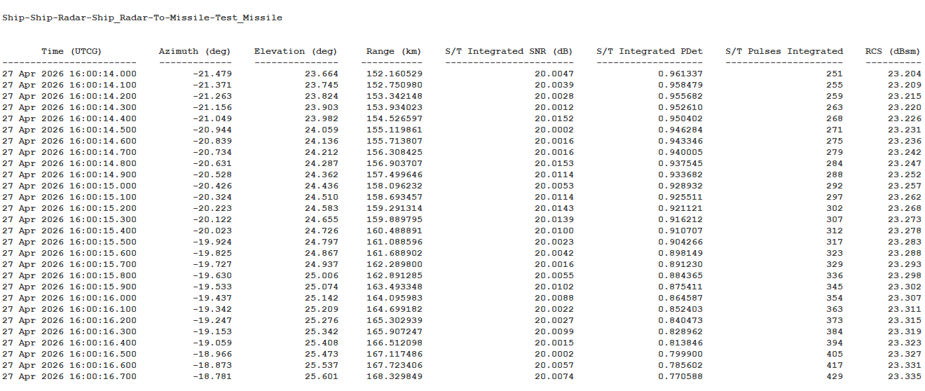
AER and Search Track Data Report
Saving your work
Clean up your workspace and save your work.
- Close any open reports, tools, and the Report & Graph Manager.
- Save () your work.
Summary
You determined that a portion of test missile's telemetry data was interfered with by the satellite radio transmissions. By using a Butterworth filter, you were able to largely mitigate the interference. Using an external antenna pattern, you model a specific shipboard radar that functioned similar to an air surveillance radar. You applied an external radar cross section file to the test missile, which modeled a specific missile type. By creating a custom report, you determined that the ship's radar was able to track the test missile for approximately 16 seconds of its flight.
On your own
Change the radar settings such as transmitter frequency and power, or receiver pre-received gains or losses, to determine their effects on your probability of detection. Experiment with the Butterworth filter to determine if you can further mitigate the interference in the link budget. Keep the current settings, but change the test missile's flight path (that is, the impact point, apogee altitude, etc.) to evaluate the effects.