STK Premium (Space) or STK Enterprise
You can obtain the necessary licenses for this tutorial by contacting AGI Support at support@agi.com or 1-800-924-7244.
The results of the tutorial may vary depending on the user settings and data enabled (online operations, terrain server, dynamic Earth data, etc.). It is acceptable to have different results.
Capabilities covered
This lesson covers the following capabilities of the Ansys Systems Tool Kit® (STK®) digital mission engineering software:
- STK Pro
- Astrogator
Problem statement
Engineers want to make a comparison between two different methods that analyze an approach to Mars. The analysis will be based on an actual mission that took place in December, 1996; the Mars Pathfinder. The first approach to be analyzed is a transfer arc between the Earth and Mars. The second analysis will analyze the mission mid-flight using a heliocentric interplanetary trajectory.
Solution
Use the STK/Astrogator® capability, model an approach to Mars using two different methods and then compare the results. In the initial setup, build a transfer arc from the Earth to Mars using a
Mars Pathfinder was launched from Earth on December 4, 1996 and landed on Mars on July 4, 1997. In the process of modeling this Mars mission, construct your own Mars Point Mass propagator and make use of the STK application's multiple 3D Graphics windows feature. Different windows allow you to view the mission from a heliocentric, Earth, and Mars-centered perspective.
What you will learn
Upon completion of this tutorial, you will be able to:
- Create multiple 3D Graphics windows with different views for situational awareness
- Use the Lambert Solver
- Create a custom transfer arc
- Create a heliocentric interplanetary trajectory
Creating a new scenario
First, you must create a new scenario, and then build from there.
- Launch the STK application (
 ).
). - Click the Create a Scenario (
 ) button.
 - Enter the following in the STK: New Scenario Wizard:
- When you finish, click .
- When the scenario loads, click Save (
 ). A folder with the same name as your scenario is created for you.
 - In the Save As window, verify the scenario name and location and click .
| Option | Value |
|---|---|
| Name | Mars_Probe |
| Location | Default |
| Start | 4 Dec 1996 00:00:00.000 UTCG |
| Stop | 1 Mar 1998 00:00:00.00 UTCG |
Save (![]() ) often!
) often!
Setting the Scenario basic time
The scenario analysis period defines the epoch and the start and stop times of your scenario. Scenario animation properties control the animation cycle, animation step definition, and the intervals between refresh updates in the 2D and 3D windows.
- In the Object Browser, open Mars_Probe's () Properties (
 ).
). - Set the Animation Step Size to 1 hr (3600 sec).
- Click .
Disabling the Subplanet Points and Labels
You'd like to see the planet orbits and not have the subplanet points and labels visible. As a reminder, changes made in 2D Graphics - Global Attributes are also applied to the 3D Graphics window.
- Select the 2D Graphics - Global Attributes properties page.
- Set the following options in the Planets section:
- Click .
| Option | Value |
|---|---|
| Show Orbits | On |
| Show Subplanets Points | Off |
| Show Subplanet Labels | Off |
Closing the 2D Graphics window
For this tutorial, the 2D Graphics window is not needed.
- Bring the 2D Graphics window to the front.
- Click the Close button found in the upper right hand corner of the window.
Inserting the Earth
The Planet object models orbital and other properties of a planet, a moon, an asteroid or the sun.
- Using the Insert STK Objects tool, insert two Planet (
 ) objects using the Insert Default method.
 - In the Object Browser, open Planet1's () Properties ().
- On the Basic - Definition page, set the Central Body to Earth.
- Set the Ephemeris Source to DE440.
- Click .
If the Planet (![]() ) object does not appear in the Insert STK Objects tool, click and add it.
) object does not appear in the Insert STK Objects tool, click and add it.
Inserting Mars
- In the Object Browser, open Planet2's () Properties ().
- On the Basic - Definition page, set the Central Body to Mars.
- Set the Ephemeris Source to DE440.
- Click .
Creating Pathfinder
The Satellite object models the properties and behavior of a vehicle in orbit around a central body.
Adding a new Satellite object
Create a new Satellite object using the Insert Default method and set its propagator to use Astrogator.
- Using the Insert STK Objects tool, insert a Satellite (
 ) object using the Insert Default () method.
 - In the Object Browser, rename the Satellite () object "Pathfinder".
- Open Pathfinder's () Properties ().
- On the Basic - Orbit page, set the Propagator to Astrogator.
Updating the spacecraft's physical properties
Update the spacecraft's physical properties to more closely match that of the real Mars Pathfinder spacecraft. Masses are based on those given in NASA's NASA Facts publication about the
- Select the Spacecraft Parameters tab.
- Set the Dry Mass to 800 kg.
- Set the Drag - Area to 20 m^2.
- Set the Solar Radiation Pressure (Spherical) - Area to 20 m^2.
- Set the Solar Radiation Pressure (Albedo/Thermal) - Area to 20 m^2.
- Select the Fuel Tank tab.
- Set the Tank Volume to 1.5 m^3.
- Set the Maximum Fuel Mass to 94 kg.
- Set the Fuel Mass to 94 kg.
- Click .
Updating the satellite's graphic properties
Set the 2D and 3D Graphics properties to better illustrate the orbital trajectory.
- Select the 2D Graphics - Pass page.
- Set the Orbit Track - Lead Type to All.
- Select the 3D Graphics - Model page.
- Locate the Detail Thresholds field.
- Slide the All slider all the way to the right to maximize the viewing distance.
- Click to save your changes and close the Properties Browser.
This moves the Model, Label, Marker, Label, Marker, and Point slider controls as well.
Renaming Pathfinder
Pathfinder is being used for the transfer arc analysis. Pathfinder Mid Flight will be used for the heliocentric interplanetary trajectory analysis.
- In the Object Browser, right-click on Pathfinder ()
- Select Copy (
 ) in the shortcut menu.
 - Right-click on Mars_Probe () and select Paste.
- Rename Pathfinder1 () "Pathfinder_midflight".
Defining three 3D Graphics windows
Next, define three separate 3D Graphics windows:
- one that gives a wide-angle view of the interplanetary cruise
- one that shows what's happening in the neighborhood of Mars
- one that shows what's happening in the neighborhood of Earth
Configuring an Earth-centered view
- Bring the 3D Graphics window to the front.
- Open 3D Graphics 1 - Earth's () Properties ().
- Select the Grids page.
- Select the Ecliptic Coordinates - Show check box.
- Select the Window Properties page.
- Change the Title to Earth.
- Select the Advanced page.
- Set the Max Visible Distance option to 1e+010 km.
- Click .
Configuring a heliocentric view
- Extend the View menu on the main toolbar.
- Select Duplicate 3D Graphics Window > Earth.
- Bring the 3D Graphics 2 - Earth window to the front.
- Set the 3D Graphic window's Central Body (
 ) to Sun.
 - Open the Properties () for the 3D Graphics 2 - Sun window.
- Select the Window Properties page.
- Change the Title to Sun.
- Select the Advanced page.
- Set the Max Visible Distance option to 1e+010 km.
- Click .
Configuring a Mars-Centered view
- Extend the View menu on the main toolbar.
- Select Duplicate 3D Graphics Window - Earth.
- Bring the 3D Graphics 3 - Earth window to the front.
- Set the 3D Graphic window's Central Body () to Mars.
- Open 3D Graphics 3 - Mars's () Properties ().
- Select the Window Properties page.
- Change the Title to Mars.
- Select the Advanced page.
- Set the Max Visible Distance option to 1e+010 km.
- Click .
Clearing the Moon's label in Globe Manager
- Select the Sun window .
- Zoom out and adjust the angle of the view so that the Earth, Mars, and Sun are all visible in the window.
- Open Globe Manager by clicking the Globe Manager (
 ) icon in the Globe Manager Toolbar found at the top of the 3D Graphics window.
 - In the Globe Manager window, right-click on the Moon and clear the Label option.

Sun-Centered View
Getting to Mars
First you can build the transfer arc using the Lambert Solver from the Component Browser in the STK application. The Lambert Solver design tool enables you to set initial and final states based on STK objects or central bodies, invoke specialized options to condition departure and arrival conditions, export a sequence based on the Lambert solution, and automate the process with Connect. For this scenario, the Lambert Solver only builds the transfer arc. Later in the scenario, you can define the parking orbit and final orbit of the spacecraft.
Creating a custom transfer arc
Use the Component Browser to begin designing the transfer trajectory for the mission. The Component Browser is a powerful tool that contains analysis components and allows you to define your own.
- Select the Utilities menu.
- Select the Component Browser option.
- In the Components list, select Design Tools.
- Click Duplicate (
 ).
). - In the Field Editor window, set the following.
- Click .
This folder contains the Lambert Solver. This component is not editable. It is designed to be the standard starting model. You can duplicate this component to create the custom mission.
| Option | Value |
|---|---|
| Name | Pathfinder Transfer |
| User Comment | Create the transfer solution for Earth to Mars |
Designing a transfer arc
You can begin defining the main central bodies that have an impact on the mission. These bodies are the Sun, Earth, and Mars. First, define the Sun.
- Double-click on Pathfinder Transfer to open Design Tools.
- Set the following options:
| Option | Value |
|---|---|
| Central Body | Sun |
| Mode | Specify initial and final central bodies |
| Initial Epoch | 4 Dec 1996 00:00:00.000 UTCG |
| Time of Flight | 212 day |
These properties define the main central body that has the largest gravitational effect, when you want to begin the mission, and how long the transfer is. Using the parameters above you have defined an important component of interplanetary travel. You know from this case that you have a good window to launch. However, for other missions these parameters would have to be considered on a case-by-case basis.
Defining the Earth Central Body
You need to go from Earth to Mars and can vary the distance to the planet and how you approach in the Radius and Angle fields.
- In the Body to Body - Departure section, set the following:
- Set the following Arrival options:
| Option | Value |
|---|---|
| Body | Earth |
| Depart from Circular Orbit | On |
| Consider Departure Body's Gravity | On |
| Option | Value |
|---|---|
| Body | Mars |
| Radius | 1.5 x Arr. Body Radius |
| Angle | 270 deg in Vel. Normal Plane |
| Insert into Circular Orbit | On |
Computing and creating a Mission Control Sequence
With Astrogator, users can design a mission in segments in a step-by-step manner. Using the Lambert Solver, you can have Astrogator design the mission control sequence for you.
- Above the Solutions section, click .
- In the Solutions section, notice the Body to body solution of the model. Review the data. The time of flight value matches the value defined earlier in your setup.
This calculates the solution with an initial low fidelity model. In this initial computation it uses the gravity of the Sun to model the trajectory of the spacecraft.
Defining the propagator
At the bottom of the Design Tools panel there is a section to design how you further analyze the mission. There is a message that says, "Propagator Requires Departure Body's Gravity". This indicates what type of propagator you should consider for the next stage in the analysis: you want to take into account the gravitational effects of Earth, which is the departing body. Remember, the Lambert Solver uses a low fidelity model in the initial calculation; however, you can increase that fidelity with one of the advanced propagators built into the STK software.
- Set the following for the Propagation:
- Click . This builds the Mission Control Sequence.
- Once the sequence has been constructed, you can take a look at what Astrogator built for you. Click . This opens the Edit Segments window and displays what Astrogator built.
- When finished, click to close the Edit Segments window.
- Click . This adds the custom sequence to the list of segments you can insert into the Mission Control Sequence (MCS) of your satellite.
- Click to close the Design Tools.
- Click to close the Component Browser.
| Option | Value |
|---|---|
| Propagator for Sequence | Earth Default High Fidelity v13 |
| Name for Sequence | Pathfinder Transfer Arc |
In the list of segments you should see an Initial State. This is the initial position of spacecraft before the thrust. Expand the Target Sequence. Inside you should see a Maneuver, Propagate, and a final Maneuver1. Note that the propagate segment is using the HPOP propagator, this is what we set in the design tools panel. Also take a look at each maneuver segment. Each segment has initial values that can be used in your calculations.
Modeling the transfer arc of the spacecraft's mission
- Open Pathfinder's () Properties ().
- Inside the MCS, remove (
 ) the default initial state and propagate segments.
 - In the MCS toolbar, click the Insert Segment After (
 ) button.
 - From the list select Pathfinder Transfer Arc (
 ).
). - Click .
- In the MCS, select the Target Sequence (
 ).
). - Change the Action to Run active profiles. This allows the STK software to iterate and calculate a new solution using the HPOP propagator.
- Click the Run Entire Mission Control Sequence (
 ) button.
 - Examine the 3D Graphics windows. You should see a trajectory from the Earth as it approaches Mars. However, note you only modeled the transfer, not the starting orbit nor the final orbit. Model those next.
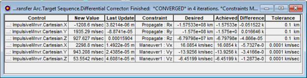
Differential Corrector Finished View
Modeling the orbit backward and forward
You built the transfer orbit from Earth to Mars, now you can model the initial orbit and the final parking orbit.
- Return to Pathfinder's () Properties ().
- In the MCS, right-click on Pathfinder Transfer Arc () and select Insert Before.
- In the Segment Selection window, select Backward Sequence (
 ).
). - Click .
- Under Pathfinder Transfer Arc (), right-click on Initial State (
 ) and select Copy.
 - Right click on backwards Sequence () and select Paste After. You are copying this initial state so that you have the same parameters for the beginning of the mission.
- Using your left mouse button, drag and drop the new Initial State () so that it is nested inside of backwards Sequence ().
- Rename the new Initial State "Backwards Initial State"
- Right click on Backwards Initial State and select Insert After.
- In the Segment Selection window, select Propagate.
- Click .
- Right click on the new Propagate (
 ) segment and select properties.
 - Set the Name to Backwards Propagate.
- Make the color different from the Propagate () segment inside of Pathfinder Transfer Arc's Target Sequence segment.
- Click .
- In the MCS, select Backward Sequence ().
- Click the Run Entire Mission Control Sequence () button.
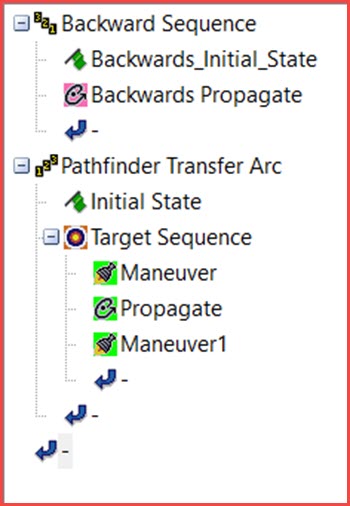
Mission Control Sequence View
You have established an orbit around Earth which can be viewed in the Earth window.
Creating a Mars point mass propagator
You are almost ready to drop into orbit around Mars. First you need to create a propagator that uses Mars as the central body.
- Extend the Utilities menu.
- Select the Component Browser.
- In the Components list, select Propagators.
- In the propagators list on the right, select Earth Point Mass.
- Click Duplicate ().
- Rename the copy Mars Point Mass.
- Click .
- Double-click Mars Point Mass.
- In the Propagators window, set the Central Body to Mars.
- Click to close the Propagators window .
- Close the Component Browser.
Propagating the orbit
You can model the injection into Mars orbit by using the newly created propagator to model the final orbit.
- Return to Pathfinder's () Properties ().
- In the MCS, right click on Pathfinder Transfer Arc () and select Insert After.
- In the Segment Selection window, select Propagate ().
- Click .
- Use the default duration stopping condition (this will model the orbit for a period of 0.5 days)
- Change the Propagator to Mars Point Mass (the component you created).
- Click .
- Click the Run Entire Mission Control Sequence button ().
- Click to close the satellite's properties.
- Examine the Mars and Earth windows.

Final MCS View
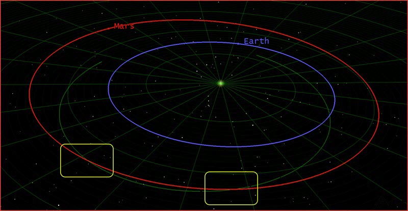
You should see the complete mission, from the initial orbit around Earth, to the transfer solution, and the final parking orbit around Mars. View the different 3D graphics windows to understand the components you've built.

![]()
Earth and Mars Views of the Transfer Arc
You have completed one approach to replicate the Pathfinder mission, you used known launch and arrival dates to model the mission. In this next stage, you can use position data from NASA and model where you know Pathfinder is and the approach to Mars.
Getting to Mars from mid-flight
In modeling interplanetary missions with Astrogator, you frequently begin with a launch from Earth or by defining a geocentric parking orbit. In this exercise, you can pull position data from NASA and start with a "snapshot" of the spacecraft in mid-mission.
Defining the initial state
From archived data, you know where Pathfinder was and when. You have gathered its position data in the heliocentric frame and can enter those in the initial state of the satellite. The heliocentric orbital elements you'll use here define the size, shape, and orientation of the Mars Pathfinder's interplanetary trajectory as of March 1, 1997. At that time, Pathfinder had been underway for about three months. You are catching the position information sometime in the middle of Pathfinder's flight.
- Open the Pathfinder_midflight's () Properties ().
- On the Basic - Orbit page, click the ellipsis (
 ) beside the Coord. System field.
 - In the Select Reference window, in the object window on the left, select Sun.
- In the Systems for: window on the right, select J2000 as the Coordinate System.
- Click .
- Select Keplerian as the Coordinate Type.
- Set the Orbit Epoch to 1 Mar 1997 00:00:00.000 UTCG.
- Enter the following orbital elements:
- Click .
| Element | Value |
|---|---|
| Semi-major Axis | 193216365.381 km |
| Eccentricity | 0.236386 |
| Inclination | 23.455 deg |
| Right Asc. of Asc. Node | 0.258 deg |
| Argument of Periapsis | 71.347 deg |
| True Anomaly | 85.152 deg |
Propagating the interplanetary trajectory
With the initial state defined, you can model the behavior of the satellite as it propagates forward in time.
- In the MCS, select Propagate ().
- Change the Propagator to Heliocentric.
- Click .
- Clear the Maximum Propagation Time check box.
- Click .
- In the Stopping Conditions field, click New ().
- In the New Stopping Condition dialog box, select Periapsis (
 ).
). - Click .
- Delete () the Duration stopping condition.
- Click the Central Body ellipsis ().
- In the Select Component dialog box, select Sun (
 ).
). - Click .
- Click .
- Click the Run Entire Mission Control Sequence () button.
- Bring the Sun window to the front.
- In the Object Browser, disable Pathfinder.
- Bring the Mars window to the front.
You are using a heliocentric propagator and defining periapsis with reference to the Sun because the spacecraft is in the heliocentric transfer phase of the interplanetary voyage, where the predominant gravitational force is that of the Sun.
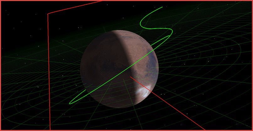
The Sun View shows that the spacecraft's trajectory intersects the orbit of Mars.
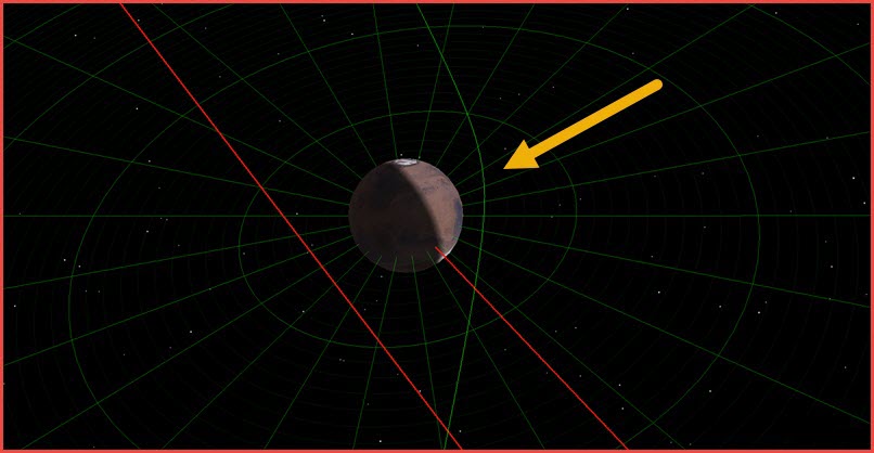
Mars Orbit Intersect
The Mars window shows that your spacecraft comes very close to Mars; it comes so close that its trajectory curves under the influence of Mars' gravity. Click Orient from Top (![]() ) and zoom out to get a good view:
) and zoom out to get a good view:
Gravitational Effect on Probe
Now change the perspective to a "side view" (i.e., about 0 deg center latitude). You'll see that your spacecraft's trajectory is substantially coplanar with the orbit of Mars.
Stopping near Mars
Your objective is not to shoot past Mars but to stop there and drop into orbit. The following steps provide one way to accomplish that goal.
- Return to Pathfinder_midflight's () Properties ().
- In the MCS, select Propagate ().
- Click the Central Body ellipsis ().
- Inside the Select Component dialog box, select Mars ().
- Click .
- Click .
- Click the Run Entire Mission Control Sequence () button.
- Bring the Mars window to the front. You'll see that the spacecraft stops quite close to Mars.
- Return to Pathfinder_midflight's () Properties ().
- In the Basic - Orbit page, double-click on the Propagate () segment to open its properties window.
- Click the Coord. System ellipsis ().
- In the Select Reference window's Object list, expand the Secondary Central Bodies folder and select Mars.
- In the Systems for: list, select Inertial.
- Click to close the Select Reference window.
- Click to close the Edit Segment window.
- Click .
You're still using periapsis as the stopping condition, but defining it with reference to Mars rather than the Sun.
Creating a Maneuver Summary report
- In the MCS tool bar, click the Summary icon (
 ).
). - Near the top of the summary, look at the date under 'Stopping Condition Information'. Recall that the Pathfinder probe landed on Mars on July 4, 1997.
- Scroll down to the entry for Altitude.
- Close the summary report.
The spacecraft comes roughly within 1,960 km of the Martian surface.
Targeting a circular orbit
- In the MCS, right-click on the Propagate () segment and select Insert After.
- In the Segment Selection list, select Target Sequence.
- Click .
- In the MCS, right-click on the Target Sequence and select Insert After.
- In the Segment Selection list, select Maneuver.
- Click .
- Use your left mouse button to nest Maneuver (
 ) inside the Target Sequence ().
 - Make certain that Maneuver Type is set to Impulsive, and set Attitude Control to Thrust Vector.
- Set the Thrust Axes to VNC(Mars).
- Make sure Cartesian is selected.
- Target () the X and Z components by clicking the small targets.
- Click .
Setting the dependent variables
- Click located below the MCS.
- Expand the Keplerian Elems directory.
- Move (
 ) Eccentricity as the sole dependent variable.
 - In the Component Details field, double click CentralBody.
- In the Component Selection window, select Mars.
- Click to close the Component Selection window.
- Click to close the Results window.
- In the MCS, select the Target Sequence ().
- In the Profiles field, open the Differential Corrector's Properties ().
- When the Differential Corrector's properties open, in the Control Parameters field, select the Use check box for both Control Parameters (independent variables):
- ImpulsiveMnvr.Pointing.Cartesian.X
- ImpulsiveMnvr.Pointing.Cartesian.Z
- In the Equality Constraints (Results) field, select the Use check box for Eccentricity (the dependent variable).
- Leave the Desired Value for Eccentricity at its default value of zero, but change Tolerance to 0.01.
- Click to close the Properties window for the Profile.
- Set the Action to Run active profiles.
- Click .
- Click the Run Entire Mission Control Sequence () button.
Propagating the orbit
- In the MCS, right-click on Target
Sequence () and select Insert After.
- In the Segment Selection list, select Propagate ().
- Click .
- In the Stopping Conditions field, click New ().
- In the New Stopping Condition dialog box, select Periapsis ().
- Click .
- Delete () Duration from the Stopping Conditions list.
- Click the Central Body ellipsis ().
- In the Select Component dialog box, select Mars ().
- Click .
- Enter a Repeat Count of 2 (to ensure that the spacecraft completes at least one full orbit pass).
- Change the Propagator to Mars Point Mass (the component you created).
- Click .
- Click the Run Entire Mission Control Sequence () button.
- Bring the Mars window to the front.
Heliocentric Orbit Complete
If you use the mouse to adjust the perspective, you'll see that your spacecraft has entered into a circular orbit around Mars.
Saving your work
- When finished, Reset (
 ) the scenario and close any reports or tools that are still open.
 - Save () your work.
Summary
Now that you have completed both approaches to Mars, take a look at their similarities and differences. Using the time of flight of Pathfinder and the Lambert Solver you were able to model your initial trajectory to Mars. You used a simplified solution and modeled the injection into orbit. You did not specify any parameters for how you entered orbit, and you assumed a circular orbit. In your second method, you knew Pathfinder's location at some point in time and walked through the steps of targeting specific parameters to approach Mars and inject Pathfinder into an orbit. Both methods focused on the same goal, but used two different approaches from Astrogator to get there.
Any sequences made in the Lambert solver are saved in the scenario directory, e.g. C:\Users\<username>\Documents\STK_ODTK 13\Mars_Probe\Astrogator\Design_Tools. For users interested in reusing built components, they can copy their sequence from this directory and save it to the STK User directory at C:\Users\<username>\Documents\STK_ODTK 13\Config\Astrogator\MCS_Segments. This is available to any other scenarios the user builds with the STK software.