STK Premium (Space) or STK Enterprise
You can obtain the necessary licenses for this tutorial by contacting AGI Support at support@agi.com or 1-800-924-7244.
The results of the tutorial may vary depending on the user settings and data enabled (online operations, terrain server, dynamic Earth data, etc.). It is acceptable to have different results.
This lesson requires STK 12.2 or newer to complete the RPO Setup. It requires 12.7 or newer to use the Passive Safety tool.
This lesson is designed to introduce you to built-in tools to help you design RPO missions. The text from this document originated from the Using STK Astrogator to plan a Rendezvous and Prox Ops Mission (L3) training.
Capabilities covered
This lesson covers the following STK Capabilities:
- STK Pro
- Astrogator
- Analysis Workbench
Problem statement
Rendezvous and proximity operations (RPO) mission planning can be a very complex process. An RPO mission planner with minimal training wants to plan an RPO mission. STK Astrogator capability has a very robust feature set that allows for complex RPO mission planning and requires significant expertise to efficiently and effectively plan an RPO mission.
After designing an RPO mission, and depending on the target of interest, operators will be interested in maintaining a keep-out sphere or box. What happens if a satellite misses a maneuver and the target is not cooperative or there is a required minimum distance? Will the actor satellite cross the keep-out sphere?
Solution
AGI has developed a set of prebuilt RPO sequences that enable an RPO mission planner to quickly and easily plan an RPO mission with just minimal training. This lesson will explore creating an RPO mission in GEO using the prebuilt templates.
In the later half of this lesson, you will explore how to define a keep-out sphere for your target satellite. Then you will explore how to maintain a passively safe actor satellite. The Passive Safety tool looks through the sequences and asses what happens if a maneuver is missed. Using the passive safety tool, you can define that keep-out regime and then modify the satellite to maintain passive safety for the entire mission.
What you will learn
Upon completion of this tutorial, you will understand:
- How to Launch the Astrogator RPO Setup
- The newly generated RPO component templates
- Build an RPO mission
- How to define a keep out sphere
- How to maintain a passively safe set of sequences
Video guidance
Watch the following video. Then follow the steps below, which incorporate the systems and missions you work on (sample inputs provided).
Create a new scenario
Create a new scenario.
- Launch STK (
 ).
). - In the Welcome to STK window, click Create a Scenario (
 ).
). - Enter the following in the New Scenario Wizard:
| Option | Value |
|---|---|
| Name: | Astrogator_GEO_RPO |
| Location: | Default |
| Start: | Default |
| Stop: | + 30 days |
- When finished, click .
- When the scenario loads, click Save (
 ). A folder with the same name as your scenario is created for you in the location specified above.
 - Verify the scenario name and location.
- Click .
Save (![]() ) often!
) often!
Part 1: RPO Setup
Launch Astrogator RPO Setup
This is an introduction to a set of prebuilt RPO sequences that were introduced with STK 12.2. These templates use VBScript. In STK 12.8, you have access to Python templates.
Prior to launching the STK 12.8 Python templates, you must install the STK Python API .whl file as well as the numpy package. The advantage with the Python templates is that you can use Python in the scripting tool in Linux. In this section you will launch the setup and then go through and examine the components that have been created.
- Select Utilities on the STK Menu bar.
- Select Astrogator RPO Setup.
- Select Load Template Files in the Astrogator RPO Setup window.
- Wait while the components are created and loaded in.
- Click when complete.
- Notice the objects loaded into the Object Browser.
Optionally, users on Linux or with a preference can enable the Use Python option. This will require you to do an optional step in the Observing RPO's Set Reference Vehicle sequence section later on in this lesson.
Component Browser Astrogator components
Before exploring the new objects, examine the Component Browser.
- Select Utilities on the STK Menu bar.
- Select Component Browser... (
 ).
). - Select Astrogator Components for the Show Component Type. This will filter the list to only show Astrogator tools.
- Expand (
 ) the MCS Segments folder (
 ).
). - Notice the newly created RPO folders listed. You'll use a variety of these templates in your mission.
- RPO Configuration
- RPO Differential Forces
- RPO Forced Motion
- RPO Matched Forces
- RPO Rendezvous
- RPO Specialized
- RPO Specialized RBar VBar
- RPO Support Sequences
- Select the various folders to view the MCS segments (
 ).
). - Close the Component Browser.
Object Browser
Move over to the Object Browser to see what objects were created.
- You should see the following objects in the Object Browser:
- Notice that most of the satellite objects (
 ) have their visualization disabled in the Object Browser.
For your specific mission, you will focus on the Target (![]() ) and RPO (
) and RPO (![]() ) satellites.
) satellites.
RPO mission building with the STK templates
Now that you've reviewed the components in your scenario, you can begin building an RPO mission. The RPO sequences in STK make it incredibly easy to expand a mission trajectory quickly. RPO sequences can do far more than what is described in this lesson. For this intro lesson, you will make a few assumptions:
- You will assume the RPO satellite has already rendezvoused with the Target. With this assumption, you will start the RPO trajectory offset in the in-track direction relative to the target.
- You will assume matched forced models for the majority of this exercise. You will touch on differential forces at the end.
- You will assume the starting position is a stable offset point relative to the target, meaning that it will not drift.
This process is lined out in the three steps below:
- The first step in building an RPO mission MCS is to define a Set Reference Vehicle sequence. It sets the reference satellite for the RPO satellite. There must always be a valid reference satellite in relative orbit calculations, but it may be updated to a different satellite later in the MCS if desired.
- The next step is to define a Set Initial State sequence. This could be an existing satellite location or a new arbitrary state. In this example, you will use the Set Initial State sequence to set an arbitrary initial position relative to your target.
- This will be followed by a Coast sequence, which propagates the satellite for a set period of time. This will give us some time to examine the physics of your offset point to ensure stability before moving into further proximity operations.
Configuring the reference vehicle
The Target satellite is your reference vehicle. The reference vehicle defines which vehicle the RPO sequences will be relative to. If a reference vehicle is not specified using a sequence, or through the Basic->Reference Vehicle page, then many sequences will not work correctly. Before executing the MCS of the Astrogator RPO satellite, you must configure the target satellite and ensure there is sufficient ephemeris generated to cover the desired mission timeframe.
- Open Target's () properties (
 ).
). - Go to the Basic - Orbit page.
- You should see a Follow (
 ) and a Prop30Days (
 ) segment.
 - Click Run Entire Mission Control Sequence (
 ).
). - Click to accept the changes and close the Properties Browser.
Opening RPO Satellite's properties
Shift your focus to the RPO Satellite. Take a look at the template MCS sequences.
- Open RPO's () properties ().
- Select the Basic - Orbit page.
- You should see three template MCS sequences (
 ).
).
| Sequence |
|---|
|
|
|
|
|
|
Observing RPO's Set Reference Vehicle sequence
Ensure the reference vehicle is set to Target (![]() ) in RPO Satellite's Reference Vehicle sequence.
) in RPO Satellite's Reference Vehicle sequence.
- Select Set Reference Vehicle ().
- Confirm the following settings:
Option Value WhoAmI RPO Reference Vehicle Target - If you selected the "Use Python" Option for the templates, then please set the following. Otherwise skip this step.
Option Value CreateOrbitSystem: True
Updating RPO's Set Initial State Sequence
Set RPO's (![]() ) Initial State.
) Initial State.
- Click Reset (
 ) in the Animation toolbar.
 - Note the Scenario time in the Animation Toolbar.
- Return to RPO's () properties () Basic - Orbit page.
- Select Set Initial State () in the MCS list.
- Set the following:
Option Value Init_InTrack_Pos: 0 m Initial_Epoch: Set to scenario start time - Keep default values for other options.
Updating RPO's Coast sequence
Propagate RPO (![]() ) for two revolutions using a Coast sequence.
) for two revolutions using a Coast sequence.
- Select Coast ().
- Set the following:
- Keep default values for other options.
| Option | Value |
|---|---|
| Coast_Duration: | 2 days |
Running the MCS
Now, you will run the Mission Control Sequence (MCS).
- Click Run Entire Mission Control Sequence ().
- Click to accept the changes and keep the Properties Browser open.
View the satellites
View the Target and RPO satellites in the 3D Graphics window. RPO (![]() ) should be in the same position as Target (
) should be in the same position as Target (![]() ).
).
- Right-click RPO () in the Object Browser.
- Select Zoom To.
- Notice RPO () is in the same position as Target ().

Adding a VBar Hop
In this step, you will go back to a matched force model and add a classic VBar Hop to your RPO mission. To initiate a VBar hop, the RPO satellite must be on the VBar to start, and then it will perform a radial maneuver to initiate a hop from one VBar position to another VBar position where a second radial maneuver is performed to stop the relative motion.
You will not be changing the engine model, but it's important to know that there are two engines that come with the RPO sequences: Rendezvous Engine and ProxOps Engine. ProxOps engine uses a small amount of thrust (1N). You can dynamically change the engine model through each sequence, but for the purposes of this exercise you are using the default models.
Updating RPO's Sequences
Update RPO's sequences to go back to a matched force model.
- Return to RPO's () properties ().
- Select Set Initial State ().
- Change Init InTrack Pos to -1000 m. This will put the RPO satellite 1 km to the west of the Target satellite on the VBar.
Inserting a VBar Hop
Add a VBar Hop to your matched force model mission.
- Right-click Coast ().
- Select Insert After....
- Expand () RPO Forced Motion ().
- Select VBar Hop () sequence.
- Click .
- Observe the settings for VBar Hop.
- Leave all parameters unchanged.
Inserting a Coast Sequence
Insert a Coast sequence to coast for 12 hours.
- Right-click VBar Hop ().
- Select Insert After...
- Expand () RPO Configuration ().
- Select Coast () sequence.
- Click .
- Change Coast_Duration to 12 hr.
- The RPO satellite MCS should now look like this:
Sequence Set Reference Vehicle Set Initial State Coast VBar Hop Coast1
Running the MCS
Now you will run the Mission Control Sequence (MCS).
- Click Run Entire Mission Control Sequence ().
- Confirm that the VBar Hop Target Sequences have converged.
- Select Coast1 ().
- Examine the Initial and Final times at the bottom of the properties panel.
- Set the scenario time to the Initial Time.
- Click Start (
 ) to animate the scenario.
 - Observe the motion in the 3D Graphics window.
- Click Reset () when finished.
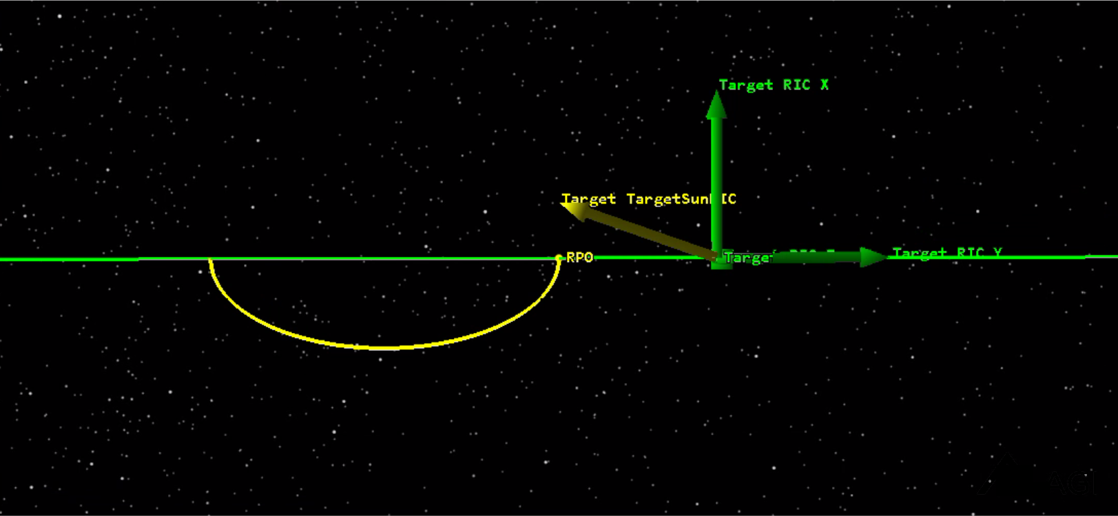
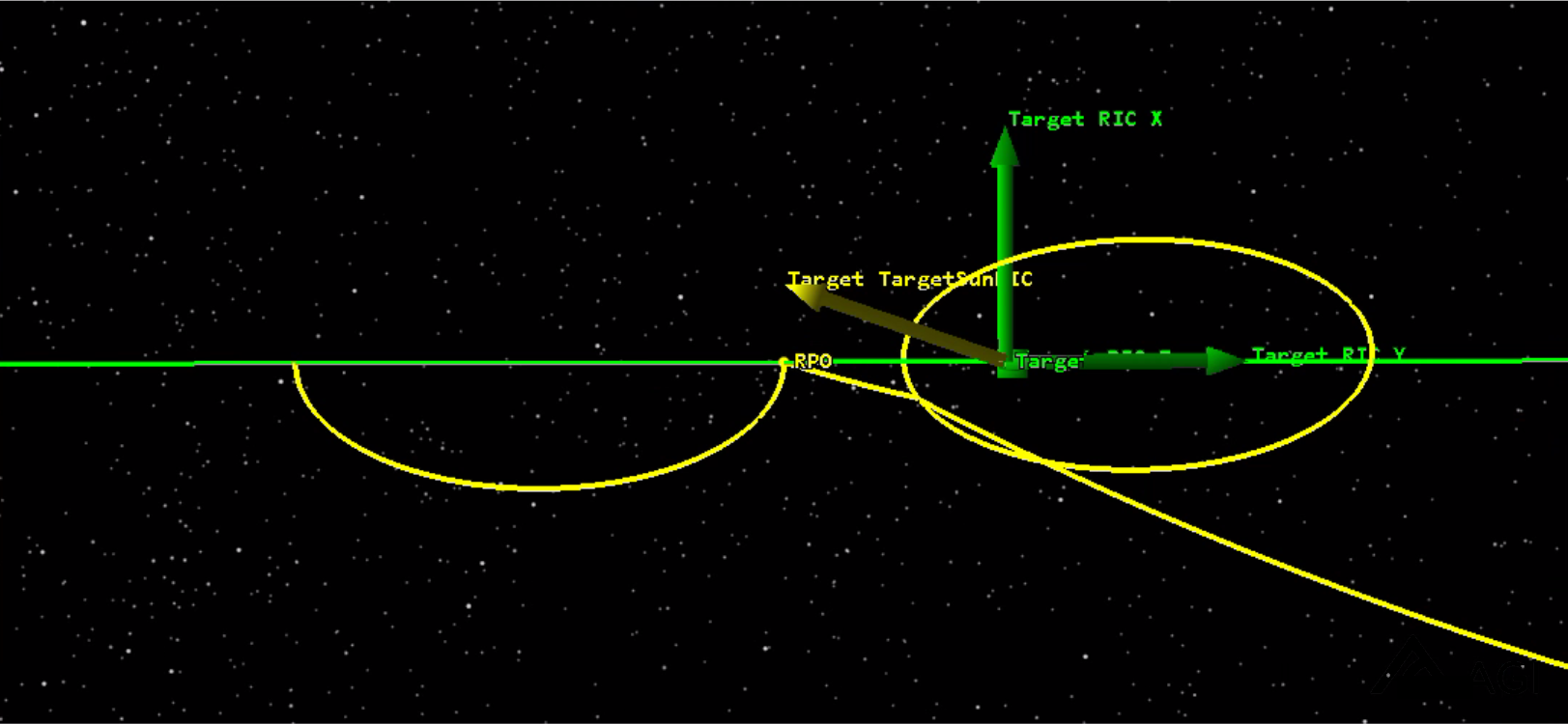
Adding a Natural Motion Circumnavigation sequence
Add a complex Natural Motion Circumnav to your matched force model mission.
In this step, you will add a Natural Motion Circumnav (NMC) at the end of your current RPO mission MCS. When force models are matched between the RPO and Target satellites, then the NMC is passively stable. The NMCircumnav sequence will determine the starting satellite state for the NMC. It will then connect the RPO satellite's current position to this NMC initial state using a forced motion waypoint to connect these positions. The NMCircumnav will not propagate past this NMC initial state, so you must add a Coast segment for as long as is desired to persist in the NMC.
Inserting an NMCircumnav sequence
Add a complex Natural Motion Circumnav to your matched force model mission.
- Return to RPO's () properties ().
- Right-click Coast1 ().
- Select Insert After....
- Expand () RPO Matched Forces ().
- Select NMCircumnav () sequence.
- Click .
- Change Transfer Duration to 10 min.
Inserting a Coast sequence
Insert a Coast sequence to coast for one day.
- Right-click NMCircumnav ().
- Select Insert After....
- Expand () RPO Configuration ().
- Select Coast () sequence.
- Click .
- Leave the default parameters. The default coast duration is one day.
- The RPO satellite MCS should now look like this:
Sequence Set Reference Vehicle Set Initial State Coast VBar Hop Coast1 NMCircumnav Coast2
Running the MCS
Again, run the Mission Control Sequence (MCS).
- Click Run Entire Mission Control Sequence ().
- Confirm that the NMCircumnav Target Sequences have converged.
- Select Coast2 ().
- Examine the Initial and Final times at the bottom of the properties panel.
- Set the scenario time to the Initial Time.
- Click Start () to animate the scenario.
- Observe the motion in the 3D Graphics window.
- Click Reset () when finished.

Exiting RPO operations
Now that you have completed a few maneuvers around the Target satellite, you are ready to exit the proximity operations. This will use a slightly larger engine than before. Keep in mind that, at this point, you are still very close to the target satellite. If you were to start up your larger engines at the current location, you could spew a flume of exhaust onto the target, which is not ideal. To avoid this, you will hop away from the target, using the smaller engines, and then exit safely.
Inserting a Hop sequence
Insert a Hop sequence at the end of the MCS.
- Return to RPO's () properties ().
- Right-click Coast2 ().
- Select Insert After....
- Expand () the RPO Forced Motion ().
- Select Hop () sequence.
- Click .
- Set the following:
| Option | Value |
|---|---|
| Desired Radial | 5000 m |
| Desired Intrack | 0 m |
| Hop Duration | 2 hr |
Inserting an Exit GEO sequence
Insert an Exit GEO sequence. The Exit GEO sequence performs a Hohmann transfer to achieve a particular drift rate, in deg/day. This means, there will be one maneuver to start the drift and a second maneuver to circularize the orbit once the desired drift rate is achieved.
- Insert an "Exit GEO" sequence from the “RPO Rendezvous” folder after the “Hop” sequence.
- Right-click Hop ().
- Select Insert After....
- Expand () the RPO Rendezvous ().
- Select Exit GEO () sequence.
- Click .
- Note that the Desired DriftRate is set to -3 deg/day.
- Leave all parameters unchanged.
Inserting a Coast sequence
Insert a Coast sequence to coast for 1 revs.
- Right-click on Exit GEO ().
- Select Insert After....
- Expand () the RPO Configuration ().
- Select Coast () sequence.
- Click .
- Set the following:
- The RPO satellite MCS should now look like this:
Sequence Set Reference Vehicle Set Initial State Coast VBar Hop Coast1 NMCircumnav Coast2 Hop Exit GEO Coast3
| Option | Value |
|---|---|
| Coast_Revs | 1 |
| Coast_Definition | Revs |
Running the MCS
Run the Mission Control Sequence (MCS).
- Click Run Entire Mission Control Sequence ().
- Confirm that the Hop and Exit GEO Target Sequences have converged.
- Click to accept the changes and close the Properties Browser.
- Bring the 3D Graphics window to the front.
- Click Start () to animate the scenario.
- Observe the motion in the 3D Graphics window.
- Click Reset () when finished.
Depending on your specific initial state/epoch, the targeter may not converge under the natural dynamics of the system due to the sensitivity of the problem. Some adjustment of initial conditions or convergence criteria for the targeter may be necessary.
Generating a report
With your RPO mission complete, examine how much fuel you consumed.
- Right-click RPO () in the Object Browser.
- Select Report & Graph Manager... (
 ).
). - Select Maneuver Summary report (
 ) in the Installed Styles list.
 - Note the Est./Act. Finite Burn Duration of each maneuver.
- Note the Delta V of each maneuver.
- Note the approximate fuel used for each maneuver.
Generating a graph
With an understanding of how much fuel you consumed, next look at how it was used. Generate a Radial, In-Track, Cross-Track (RIC) graph and examine the behavior of the RPO satellite throughout the entire mission.
- Right-click RPO () in the Object Browser.
- Select Report & Graph Manager... ().
- Select RIC graph (
 ) in the Installed Styles list.
 - Select
- In the Assigned Object Window, the Target satellite.
- Click .
Updating the graph
Update the graph's axes to see the proximity operation data in more detail.
- Double-click inside the graph.
- Select the Axis tab.
- Set the Y Axis to Min/Max.
- Set the levels to +/- 1.5.
- Click .
- Right-click in the graph.
- Select Set Animation Time to jump to that time in the scenario.
- Review that moment in the 3D Graphics window to understand each stage of the mission.
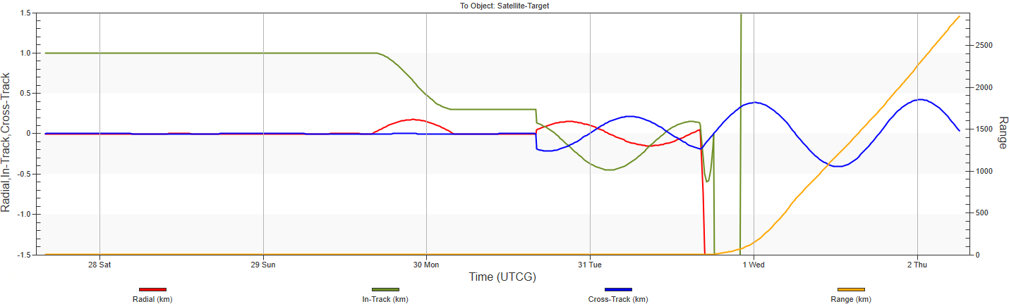
The RIC graph shows the relative relationship between RPO (![]() ) and Target (
) and Target (![]() ).
).
Save your work
- When finished, close any open reports, properties, and the Report & Graph Manager.
- Save () your work.
Summary of Part 1
In this lesson you launched the Astrogator RPO Setup and reviewed the components it added to the scenario. Then you used a handful of the sequences to model your own RPO mission. Lastly, you generated a maneuver summary report and an RIC graph.
Part 2: Passive Safety tool
After designing an RPO mission, and depending on the target of interest, operators are interested in maintaining a keep-out sphere or box. The Passive Safety tool addresses what happens if a satellite misses a maneuver, and the target is not cooperative or there is a required minimum distance. Will the actor satellite cross the keep-out sphere? This tool looks through the sequences and assesses what happens if a maneuver is missed. Using the Passive Safety tool, you can define that keep-out region and then modify the satellite to maintain passive safety for the entire mission.
Opening the Passive Safety tool
The Passive Safety tool is available from the Utilities menu. Use the drop-down menu to select it.
- Select Utilities on the STK Menu bar.
- Select Astrogator - Passive Safety.
Astrogator Passive Safety
When the Astrogator Passive Safety tool opens, you will see Satellite Options, Constraint Options, Time Options, and Analysis Interval Options at the top. After you run the analysis, the table will populate with information.
Entering Satellite Options parameters
The first fields you will fill in are in the Satellite Options section. You must define the Actor and the Target. The Actor satellite must use Astrogator as a propagator. The Target satellite does not have this restriction. The tool will find and use all maneuvers that are Finite or Impulsive for analysis.
- Select Target for the Target option.
- Set the Actor to RPO.
- Note the updated time intervals.
When you select the Actor or Target, the availability interval below will update appropriately. After updating the Target or Actor selection, STK updates the Analysis Interval Options interval to reflect what the max analysis interval values would be based on the values of the given Target and Actor satellite.
Setting Constraint Options parameters
You'll explore a keep-out sphere and use the Spherical option. You know that the RPO satellite will get close to the Target satellite, but you don't want RPO to collide or get to close. Therefore, you want your satellite to stay about 0.150 km away.
- Select the Spherical radio button.
- Set the Radius to 0.15 km.
- Click .
- In the table, review the seven maneuvers.
- Select the Display Proximity Geometry button to visualize the keep-out sphere.
- You see that a portion of RPO's () trajectory intersects with the sphere. In the table, you can see this clearly labeled.
- Examine maneuver 4.
- Double-click the row of maneuver 4. In the table, maneuver 4 is considered unsafe.
The columns of information show the number of maneuvers, the safety status, the maneuver time, the range, and the radial, in-track, and cross-track distances.

Unsafe means that if you miss maneuver 4, then maneuver 5 will be unsafe and you run into the keep out sphere.

You need to examine this further and explore solutions to make your maneuver sequences safe.
Acknowledging the PassiveCheck satellite
A temporary satellite object has appeared in the object browser, PassiveCheck (![]() ). The PassiveCheck satellite is created and used for analysis and display purposes. STK creates it during the analysis and keeps it around so long as there is more than one maneuver. STK uses it to display the selected maneuvers. STK removes it when you close the Passive Safety tool. You can make the visuals a bit more identifiable. This section is optional.
). The PassiveCheck satellite is created and used for analysis and display purposes. STK creates it during the analysis and keeps it around so long as there is more than one maneuver. STK uses it to display the selected maneuvers. STK removes it when you close the Passive Safety tool. You can make the visuals a bit more identifiable. This section is optional.
- Open the PassiveCheck () satellite's properties.
- In the Basic - Orbit tab, change the Propagate segment's color to purple (or another preferred color).
- Run the MCS ().
- Click .
Generating RPO's Maneuver Summary report
Your actor satellite is the RPO satellite, and it is the satellite conducting the maneuver that has an unsafe sequence. You want to understand that unsafe maneuver a bit more by generating a maneuver summary report to understand when the maneuver takes place in the sequence. Then you'll modify the RPO's properties to make the entire sequence safe.
- Right-click the RPO satellite from the Object Browser.
- Select Report & Graph Manager.
- Generate a Maneuver Summary report for the RPO satellite.
- Examine the seven sequences and take a closer look at manuever 4, which supports NMCircumnav.Final_Hop.Target_Sequence.Match_Velocity. This is the sequence that you will modify to make the entire set of maneuvers safe.
- Save the report as a quick report.
Making the maneuvers safe
You know from the passive safety tool and the Maneuver Summary report that the NMCircumnav contains the unsafe maneuver. Dive into RPO (![]() ) satellite's MCS and change a component to explore how you can make the entire sequence safe. You can consider aspects of the NMC. For example, regarding the size of the NMC (Rbar or Vbar), can you change a dimension and make the sequence safe? Or, does when you enter the NMC (initial phase angle) have an impact? Do changes in the duration of the transfer or the in-track direction affect the safety?
) satellite's MCS and change a component to explore how you can make the entire sequence safe. You can consider aspects of the NMC. For example, regarding the size of the NMC (Rbar or Vbar), can you change a dimension and make the sequence safe? Or, does when you enter the NMC (initial phase angle) have an impact? Do changes in the duration of the transfer or the in-track direction affect the safety?
- Open the RPO () satellite's properties.
- In the Basic - Orbit tab, in the MCS, select NMCircumnav.
- In the panel, notice the listed parameters. You will explore the following:
- RBar CrossTrack Offset
- VBar CrossTrack Offset
- Init Phase Angle
- Transfer Duration
- InTrack Offset
You will run the MCS many times and generate many Targeting Status Windows. To close two or more status windows, select the target icon in a target status window and select "Close All Targeting Status Windows".
Adjusting the RBar CrossTrack Offset
- Change the RBar CrossTrack Offset to -200 m.
- Run the MCS ().
- In the Passive Safety tool window, click .
- You can see that the sequence is not safe.
- Return to RPO satellite's properties.
- Change the RBar CrossTrack Offset back to -150 m.
Adjusting the VBar CrossTrack Offset
- Change the VBar CrossTrack Offset to +200 m.
- Run the MCS ().
- In the Passive Safety tool window, click .
- You can see that the sequence is not safe.
- Return to RPO satellite's properties.
- Change the VBar CrossTrack Offset back to 150 m.
Adjusting the Init Phase Angle
- Change the Init Phase Angle to -40 deg.
- Run the MCS ().
- In the Passive Safety tool window, click .
- You can see that the sequence is not safe.
- Return to RPO satellite's properties.
- Change the Init Phase Angle back to -80 deg.
Adjusting the Transfer Duration
- Change the Transfer Duration to 30 min.
- Run the MCS ().
- In the Passive Safety tool window, click .
- You can see that the sequence is not safe.
- Return to RPO satellite's properties.
- Change the Transfer Duration back to 10 min.
Adjusting the InTrack Offset (making the maneuver safe)
- Change the InTrack Offset to 50 m.
- Run the MCS ().
- In the Passive Safety tool window, click .
- You can see that the sequence is safe! You have achieved a passively safe set of sequences!
- Rotate the view in the 3D graphics display to confirm this change visually.

Exporting the results
Now that you have achieved a set of safe sequences, export the reports.
- Return to the Passive Safety tool.
- Select the export to .csv file (
 ) button.
 - Save () your work.
On your own
In your study, you defined a keep-out sphere. On your own, define a keep-out box. Repeat this exercise, generating a maneuver summary report and making changes to the MCS to figure out how to maintain a passively safe set of sequences.
Part 2 summary
In this section, you explored the Passive Safety tool by defining a keep-out sphere. After analyzing the mission, you explored what changes you could make to a maneuver to make the entire sequence of maneuvers safe.
Appendix: relative orbits description
The Physics of RPO missions was not directly discussed in this lesson. This appendix provides additional clarity. This information is for reference only and is not directly discussed in the training video.
1.0 Introduction
There are two main categories of relative orbits:
- Natural Motion: Natural motion relative orbits require little or no Delta-V to maintain the desired relative orbit.
- Forced Motion: Forced motion relative orbits require frequent Delta-Vs to maintain the desired relative orbit.
There are only a couple of natural-motion relative orbits that are widely used, and those include a VBar (intrack) offset and the 2:1 circumnav ellipse. As the desired standoff distances of these increases, the force model differences start to impact the length at which these relative orbits are stable. It will require a station-keeping maneuver to return to the desired relative orbit conditions. Any difference in solar radiation pressure or drag force, typically due to different area-to-mass ratios or a different surface area exposed to the sun, will also cause these "stable" relative orbits to move away from their desired relative positions.
There are many forced-motion relative orbits that are widely used. These generally follow a desired relative path. They require frequent Delta-Vs to follow that desired relative path. Some common forced-motion relative orbits include: tear drop, perch point, forced motion circumnav, and hops from one relative point to another. Depending on the relative distance from the target and the timing of the desired motion, these may require anywhere from infrequent and small Delta-Vs to very frequent and larger Delta-Vs.
Most relative orbits discussed in this tutorial are based on the Clohessy-Wiltshire equations, which have, as assumptions, circular two-body Keplerian orbits. Once you start to have large distances where the forces acting on the two satellites is appreciably different, then these natural-motion relative orbits take on different shapes. Also, as you move to more eccentric orbits, the same thing applies. Natural-motion and forced-motion relative orbits are still possible in non-Keplerian and eccentric orbits; it is just a more “interesting” game!
The following figure shows some of the common relative orbits in use today.
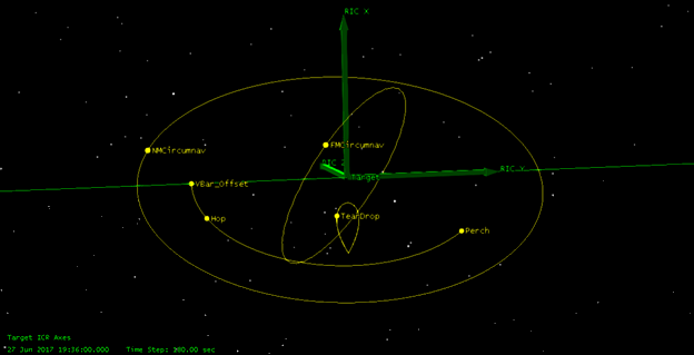
Figure 1.1. Some common relative orbits in use today
The Space Event Generator, SEG, provides options to use the two natural-motion relative orbits as proximity operations solutions. These are described in further detail below.
2.0 V-Bar Offset natural-motion relative orbit
The V-Bar Offset relative orbit is one where the proximity satellite moves to an in-track position relative to the target satellite. This is one of the natural-motion relative orbits that generally requires little or no Delta-V to maintain this relative position to the target satellite. In figure 2.1, you can see that this relative orbit appears as a point in space along the negative or positive in-track direction of the target satellite.

Figure 2.1. V-Bar Offset relative orbit for a circular target
The valid ranges for a “stable” V-Bar Offset is from just a few meters to 100 km for circular orbits. For eccentric orbits, there is a lot more motion throughout the orbit and the relative orbit is no longer a point but rather has other relative motion. See figure 2.2 for a HEO orbit V-Bar Offset that shows motion in both radial and in-track directions during the orbit period.

Figure 2.2. V-Bar Offset relative orbit for a HEO target
The V-Bar Offset relative orbit is about the easiest of all the relative orbits to implement using Astrogator. The nuance in targeting the correct initial conditions has to do with the differing force models between the relative orbit satellite and the target satellite. In general, when sitting on the VBar, you can ignore the cross-track component, as both objects will experience nearly the same out-of-plane orbit perturbations, as long as the orbit planes fully match at the initial conditions. The farther the VBar offset distance, the more the radial and in-track accelerations will start to differ and require some “tweaking” of the initial conditions to maintain the VBar offset relative position as long as possible.
3.0 Natural Motion Circumnav relative orbit
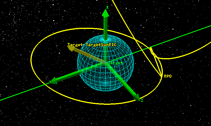
The Natural Motion Circumnav (NMCircumnav) relative orbit is one where the proximity satellite circumnavigates the target satellite in a 2:1 ellipse, where the major axis is twice the distance of the minor axis. This is another natural-motion relative orbit that generally requires little or no Delta-V to maintain the relative orbit with respect to the target satellite. In figure 3.1, you can see one full revolution of the NMCircumnav. In this figure, the NMCircumnav is completely in the orbit plane. However, cross-track components are also possible in this relative orbit.

Figure 3.1. The Natural Motion Circumnav orbit for a circular target satellite
The valid ranges for a “stable” NMCircumnav vary from just a few meters to 10 km for circular orbits. For eccentric orbits, the NMCircumnav takes on different shapes but still circumnavigates to target satellite. See figure 3.2 for a HEO orbit NMCircumnav that shows a new shape for the relative orbit.

Figure 3.2. The Natural Motion Circumnav orbit for a HEO target satellite
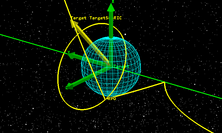
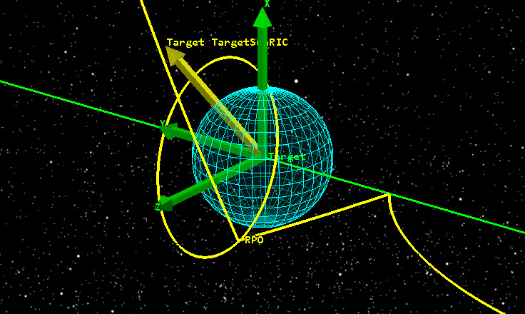
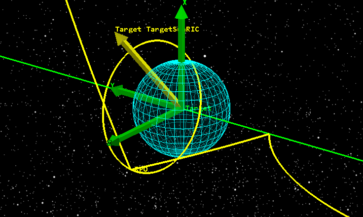
Cross-track components to the circumnavigation are possible. Figure 3.3 shows a complex cross-track component while circumnavigating a circular GEO satellite. In this configuration, the circumnavigation never directly crosses the RBar or the VBar, which may be a desirable circumnavigation from a safety standpoint since neither a target in-track nor target cross-track Delta-V would collide with the relative circumnavigation orbit.
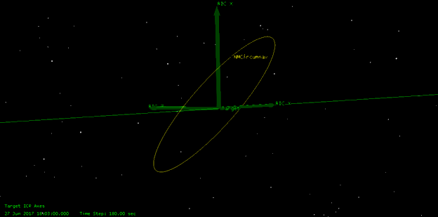
Figure 3.3. The Natural Motion Circumnav orbit for a HEO target satellite
The NMCircumnav relative orbit is fairly simple to implement using Astrogator, and there are several ways to implement it in Astrogator. You can define the semiminor axis, which is in the radial axis of the target satellite. This puts the initial condition at a strictly radial position component relative to the target satellite. The radial offset is the desired semiminor axis of the circumnavigation. Now, at the same time, the in-track velocity must be targeted to achieve the natural motion circumnavigation conditions, and the cross-track velocity must be targeted to achieve the desired cross-track component when crossing the target in-track/cross-track plane (along the VBar).
The NMCircumnav uses these parameters:
- Relative Semiminor Axis – This is the desired circumnavigation semiminor axis distance from the target satellite in the radial direction from the target satellite. A negative value indicates the desired offset is in the negative radial direction relative to the target satellite when the target satellite is at apogee. This selection generally produces a lower eccentricity orbit than the target, unless the target is already circular or nearly circular. A positive value indicates the desired offset is in the positive radial direction relative to the target satellite at apogee. This selection generally increases the eccentricity of the relative orbit. Valid values range from just a few meters to 10 km.
- RBar CrossTrack Offset – This is the cross-track component when on the RBar, which is nadir if the semiminor axis is negative or zenith if the semiminor axis is positive.
- VBar CrossTrack Offset – This is the cross-track component when crossing the first VBar after the Cross-Track Offset time. By combining Cross-Track Offset and Plane Crossing Offset, you can design a circumnavigation that does not cross directly in front, behind, over the top, or under the target satellite. This is seen as a “safe” circumnavigation since the likely maneuvers a target satellite may perform are generally in-track or cross-track.