STK Premium (Air) or STK Enterprise
You can obtain the necessary licenses for this tutorial by contacting AGI Support at support@agi.com or 1-800-924-7244.
This lesson requires an internet connection and version 13.0 of the STK software or newer to complete in its entirety.
The results of the tutorial may vary depending on the user settings and data enabled (online operations, terrain server, dynamic Earth data, etc.). It is acceptable to have different results.
Capabilities covered
This lesson covers the following capabilities and tools of the Ansys Systems Tool Kit® (STK®) digital mission engineering software:
- STK Pro
- Aviator
Problem statement
Aircrew and mission planners require analytical tools to simulate real-world aircraft performance, ones which account for variations in airframe characteristics and mission requirements. You are designing a test plan for a high-performance aircraft flying out of Buckley Space Force Base (SFB). During the flight, the pilot will execute various maneuvers to see how they affect the overall performance of the aircraft.
Solution
Use the STK software's Aviator capability to build and simulate the aircraft's maneuvers with a full six degrees of freedom (6DoF), modeling the pilot's inputs to the flight controls with Dynamic Control procedures. Then, use a custom report to analyze how various maneuvers affect the aircraft's flight characteristics, such as stall and recovery speeds and required thrust in high-angle climbs.
What you will learn
Upon completion of this tutorial, you will understand the following:
- How to use the Aviator Catalog Manager and the Aviator catalog interface to insert mission elements
- How to model an aircraft mission using the Aviator propagator
- How to use Aviator tools to define an aircraft and to create and modify phases and procedures of a mission
- How to use the Dynamic Control Fixed Wing Acceleration performance model
- How to use Dynamic Control procedures to simulate an aircraft with six degrees of freedom
Video guidance
Watch the following video. Then follow the steps below, which incorporate the systems and missions you work on (sample inputs provided).
Creating a new scenario
First, you must create a new scenario and then build from there.
- Launch the STK application (
 ).
). - Click
 Create a Scenario in the Welcome to STK dialog box.
 - Enter the following in the STK: New Scenario Wizard:
- Click when you finish.
- Click Save (
 ) when the scenario loads. The STK application creates a folder with the same name as your scenario for you.
 - Verify the scenario name and location in the Save As dialog box.
- Click .
| Option | Value |
|---|---|
| Name | Aviator_DynControl |
| Location | Default |
| Start | Default (recommend changing the time to 18:00:00.000 UTCG for daylight) |
| Stop | + 30 min |
Save (![]() ) often during this scenario!
) often during this scenario!
Using the Aviator Catalog Manager
The STK software's
Opening the Aviator Catalog Manager
Open the Aviator Catalog Manager from the Utilities menu.
- Select the Utilities menu.
- Select Aviator Catalog Manager... (
 ).
).
Loading navigation data using the Aviator Catalog Manager
ARINC424 data files are the only valid data sources for NAVAID and airport sites. Load a sample ARINC424 data file containing navigation information into the STK application. The data file is included with your STK installation.
If you have completed other Aviator tutorials, you may have already loaded the sample ARINC424 data file into the STK application.
- Resize the Aviator Catalog Manager window by extending it out to the right so that you can see more space in the large, blank area.
- Expand (
 ) Runway (
 ).
). - Select ARINC424 runways (
 ).
). - Click the Use Master Data File ellipsis (
 ).
). - Navigate to <Install Dir>\Data\Resources\stktraining\samples when the Open dialog box appears.
- Select the FAANFD18 data file.
- Click to select the file and to close the Open dialog box.
- Click when you return to the Aviator Catalog Manager.
- Close (
 ) the Aviator Catalog Manager.
Inserting an Aircraft object
Insert an
- Bring the Insert STK Objects tool (
 ) to the front.
 - Select Aircraft (
 ) in the Select An Object To Be Inserted list.
 - Select Insert Default () in the Select A Method list.
- Click .
- Right-click on Aircraft1 () in the Object Browser.
- Select Rename in the shortcut menu.
- Rename Aircraft1 () DynC_Acft.
Using the Aviator propagator
With the Aviator capability, the aircraft's route is modeled by a sequence of curves parametrized by well-known performance characteristics of aircraft, including cruise airspeed, climb rate, roll rate, and bank angle. The precise state of an aircraft at any given time can be computed analytically. To utilize the Aviator capability, you must first set your aircraft to select Aviator as its propagator.
- Right-click on DynC_Acft () in the Object Browser.
- Select Properties (
 ) in the shortcut menu.
 - Select the Basic - Route page when the Properties Browser opens.
- Open the Propagator drop-down list.
- Select Aviator.
- Click to confirm your selection and to keep the Properties Browser open.
- Review the information in the Flight Path Warning dialog box.
- Click to set the scenario globe reference to Mean Sea Level (MSL) and the Animation mode to X Real Time.
- Click to close the Fight Path Warning dialog box.
Aviator performs best in the 3D Graphics window when the surface reference of the globe is set to MSL instead of the default reference of WGS84. Likewise, setting the animation mode to X Real Time allows for smoother animation and better data display performance.
Configuring an Aviator mission
The Mission window is used to define the aircraft's route when Aviator is used as the propagator. The Mission window contains three toolbars — Initial Aircraft Setup, Phases of Flight, and Procedures and Sites — that enable you to define the aircraft that you are modeling and to create, modify, and delete phases and procedures.
Creating a custom aircraft model
The buttons on the Initial Aircraft Setup toolbar are used to define the aircraft model that will be used in the mission. An aircraft model defines the physical characteristics of an aircraft, the aircraft's configuration, and the performance models that define how it flies in a given situation. The basic models found in Select Aircraft dialog box are representative of an aircraft type, but not a specific aircraft. It's up to you to customize the model you choose to match actual aircraft characteristics.
- Click Select Aircraft (
 ) In the Initial Aircraft Setup toolbar.
 - Right-click on Basic Fighter (
 ) in the User Aircraft Models () when the Select Aircraft dialog box opens.
 - Select Duplicate in the shortcut menu.
- Right-click on Basic Fighter Copy ().
- Select Rename in the shortcut menu.
- Rename Basic Fighter Copy () DynC_Fighter.
- Select DynC_Fighter () in the User Aircraft Models () list.
- Click to close the Select Aircraft dialog box.
- Click .
Note that Basic Fighter (![]() ) is read only (
) is read only (![]() ). Read-only items in the Aviator Catalog Manager cannot be modified, so you must duplicate the built-in aircraft model to make any modifications.
). Read-only items in the Aviator Catalog Manager cannot be modified, so you must duplicate the built-in aircraft model to make any modifications.
Creating a new performance model
The Aircraft Properties provide access to
- Click Aircraft Properties (
 ) in the Initial Aircraft Setup toolbar.
 - Right-click on Acceleration (
 ) in the Performance Models list in the DynC_Fighter dialog box.
 - Select Add New Model Type... in the shortcut menu.
- Select AGI DynC Fixed Wing Acceleration Model in the New Types list when the Add New Model Type dialog box opens.
- Click to confirm and to close the Add New Model Type dialog box.
Using the Dynamic Control Fixed Wing Acceleration performance model
The Dynamic Control Fixed Wing acceleration model provides a force and moment model for Dynamic Control procedures, which implement a simple Fixed Wing model with aerodynamics, propulsion and flight control systems. The Dynamic Control Fixed Wing performance model is comprised of four tabs: Basic, Aerodynamics, Propulsion, and Flight Control. The Basic tab defines the turn rate behavior, climb/descent transitions, attitude transitions, and control authority information. The Aerodynamics and Propulsion tabs allow you to select and define strategies to model attitude and propulsion characteristics. The Flight Control tab allows you to set the control ranges.
Using the FighterAero aerodynamics strategy
The FighterAero strategy model is a generalization of the F-16 model from “Aircraft Control and Simulation: Dynamics, Controls Design, and Autonomous Sysytems" by Brian L. Stevens, Frank L. Lewis, and Eric N. Johnson. It contains a variety of aerodynamic tables, which, for the F-16, are derived from wind tunnel data. This model version is generalized to allow you to supply different tables; however the form of the model is fixed. The idea is that this model is similar to other fighters, but one not altogether different from an F-16.
- Select the Aerodynamics tab.
- Keep the default strategy setting of FighterAero.
Using the FighterProp propulsion strategy
The FighterProp strategy model is closely modeled from the Stevens F-16. The thrust is primarily computed from a set of three tables, which are indexed by mach and altitude. Through the different models of operation, these tables are interpolated to arrive at the thrust.
- Select the Propulsion tab.
- Keep the default strategy setting of FighterProp.
When using the Dynamic Control Fixed Wing Acceleration performance model in actuality, careful attention should be taken to ensure the weights and inertial matrices in the chosen aircraft match those of the F-16 fighter aircraft; otherwise, you should update the aerodynamics and propulsion strategies for your chosen aircraft model (wing areas, propulsion, etc.).
Using the FixedWingFlightCtrl strategy
The FixedWingFlightCtrl strategy stores the control ranges; the underlying aerodynamics model uses normalized -1,1 ranges. The strategy also implements any desired autopilot modes.
- Select the Flight Control tab.
- Look in the Controls panel.
- Look in the VXF panel.
- Click .
- Click to close the DynC_Fighter dialog box.
- Click .
These are the actuators of the flight control. They represent pilot stick control, which, for fixed wing are elevator, aileron, rudder, and throttle. The max deflections for the control surfaces are the max in the positive and negative directions.
This field represents autopilot mode. The Course Snap option controls how aggressively the plane turns while in autopilot mode. The MaxBank value comes from the "Basic" tab bank angle.
Linking the performance model to the mission phase
Phases are the basic units of an aircraft's mission, and serve as containers for the procedures that define the aircraft's actions. Every mission must have at least one
- Right-click on Phase 1 in the Mission List.
- Select Phase Properties ... (
 ) in the shortcut menu.
 - Right-click on Acceleration in the Model Type list when the Phase 1 properties dialog box opens.
- Select Link to Catalog... in the shortcut menu.
- Select AGI DynC Fixed Wing Acceleration Model when the Link to Catalog (Acceleration) dialog box opens.
- Click to confirm and to close the Link to Catalog (Acceleration) dialog box.
- Click to close the Phase 1 properties dialog box.
- Click .
The Mission List provides an overview of the mission by listing each of the mission phases and the procedures within them, in the order in which they will be executed. Both phases and procedures are displayed in the Mission List.
Changing the aircraft's configuration
The
Updating the aircraft's basic configuration
The Basic tab is used to define the empty parameters of the aircraft, and displays the total values, based on the stations and fuel tanks defined for it.
- Click Configuration (
 ) in the Initial Aircraft Setup toolbar.
 - Select the Basic tab when the Aircraft Configuration dialog box opens.
- Enter 19100 lb in the Empty Weight field.
- Note the Max Landing Weight value of 35500 lb.
- Note the Total Weight value of 38100 lb.
This is where you add payload weight. In this instance, the weight will account for the pilot, instructor, any passengers and baggage.
This is the empty weight plus the default fuel weight of DynC_Acft.
Updating the aircraft’s fuel configuration
The Stations tab is used to define the aircraft's internal fuel tanks, stations, and external fuel tanks that are attached to the stations.
- Select the Stations tab.
- Select Internal Fuel (
 ).
). - Enter 7000 lb in the Capacity field.
- Enter 3000 lb in the Initial state field.
- Click to confirm your fuel changes.
- Click to confirm your changes and to close the Aircraft configuration dialog box.
- Click .
This is the internal fuel capacity of the aircraft.
You will start with 3,000 pounds of fuel. At the end of the simulation, you will analyze data to determine if you require less or more fuel for the mission.
Updating the Mission Profile
The
- Right-click in the Mission Profile.
- Select Profile Options/Properties... in the shortcut menu.
- Select the Secondary Y Axis check box in the Profile Options/Properties dialog box.
- Select True Air Speed in the Secondary Y Axis list.
- Click to confirm your selection and to close the Profile Options/Properties dialog box.
- Click .
Building the aircraft's mission
The Aviator capability is built upon the concept of an aircraft's mission, as opposed to a mere point-to-point route. You have set up and defined the aircraft model, the singular phase of the mission, and its associated Dynamic Control Fixed Wing acceleration performance model. Now, insert and define the sites and procedures that the aircraft will execute for its mission.
Using a Dynamic Control Trim Point
Insert a ![]() ) site to use a Dynamic Control procedure as the first procedure in a mission. It is the simple placement of the aircraft in space, with a course, velocity, flight path angle, and turn rate.
) site to use a Dynamic Control procedure as the first procedure in a mission. It is the simple placement of the aircraft in space, with a course, velocity, flight path angle, and turn rate.
- Select the Basic – Route page.
- Click Insert Procedure After (
 ) in the Procedures and Sites toolbar.
 - Select DynCTrimPoint (
 ) in the Select Site Type list in the Site Properties dialog box.
 - Enter the following parameters in the State panel:
- Click .
| Option | Value |
|---|---|
| Latitude | 39.6 deg |
| Longitude | -104.68 deg |
| Altitude | 15000 ft |
| Course | 151.4 deg |
| TAS True Airspeed: the speed that the aircraft is moving relative to the airmass that it is flying in. | 400 nm/hr |
Inserting a Dynamic Control procedure
The
You already activated a Dynamic Control Fixed Wing Acceleration performance model to use this procedure. This performance model can also be used for other procedures such as Basic Maneuver, which is why you set it for the entire phase of your mission. In this case, the performance model uses a trim algorithm to create the aeropropulsion data based directly on the same unit which flies the Dynamic control.
In your first Dynamic Control procedure, the pilot will trim the aircraft and fly down range for 10 nautical miles
- Select DynamicControl (
 ) in the Select Procedure Type list in the Procedure Properties dialog box.
 - Enter Trim 10 Nautical Miles in the Name field.
- Leave the default Trim Hold strategy.
- Set the following parameters in the Basic Stop Conditions panel:
- Click to confirm your selections and to close the Procedure Properties dialog box.
- Click .
| Option | Value |
|---|---|
| Fuel State | Cleared |
| Time of Flight | Cleared |
| Downrange | 10 nm |
Inserting an End of Previous Procedure site type
In this instance, you want to switch to a Dynamic Control procedure at the end of your previous procedure. A Dynamic Control procedure can follow either a Dynamic Control Trim Point site or End of Previous Procedure site for most Aviator procedures.
- Click Insert Procedure After () in the Procedures and Sites toolbar.
- Select End of Previous Procedure (
 ) in the Select Site Type list in the Site Properties dialog box.
 - Click .
Using the VXF strategy
The pilot will turn the aircraft to a heading The direction that the aircraft is pointing. of 90 degrees, maintain its current altitude, and increase its speed to 600 nautical miles per hour.
- Select DynamicControl () in the Select Procedure Type list in the Procedure Properties dialog box.
- Enter Fly 90 Degrees in the Name field.
- Open the Strategy drop-down list.
- Select VXF.
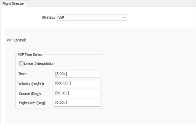
Setting the VXF control parameters
Currently, the aircraft is flying at a speed of 400 nautical miles per hour. You want to increase speed to 600 nautical miles per hour and turn to a heading of 90 degrees. Use the Velocity, Course, Flight Path Angle (VXF) controller, which uses nonlinear dynamic inversion to attain these three parameters, and enter the changes as a series of time points. The points are interpolated when Linear Interpolation is selected; otherwise, they are taken as step commands.
- Enter Time: [5.00; ] in the Time field in the VXF Time Series Panel.
- Enter [600.00; ] in the Velocity (nm/hr) field.
- Enter [90.00; ] in the Course (Deg) field.
- Enter [0.00; ] in the Flight Path (Deg) field.
The Time VXF control is a series of increasing time points. The time points are not checked against the procedure duration, but are only used when they fall in range. This begins your aircraft's maneuver five (5) seconds after the end of the previous maneuver.
Be sure to include the space following the semicolon (;) in the expression.
The Velocity VXF control is an ECF velocity to achieve corresponding to the time series. Your aircraft will begin to increase its speed to 600 nautical miles per hour, based on its performance characteristics.
The Course VXF control is a course to achieve corresponding to the time series. Your aircraft will turn to a course of 90 degrees based on its performance characteristics.
The Flight Path VXF control is a flight path angle to achieve corresponding to the time series. Your aircraft will remain in level flight.
dynamic control properties
This is an introduction to using dynamic control properties. You only used one set of times in the VFX Time Series panel. However, you could insert multiple times and maneuvers. You will try this later in the scenario.
Setting the basic stop condition
Give the aircraft time to increase its speed.
- Set the following parameters in the Basic Stop Conditions panel:
- Click .
- Click .
| Option | Value |
|---|---|
| Fuel State | Cleared |
| Time of Flight | 00:01:00.000 HMS |
| Downrange | Cleared |
Inserting an End of Previous Procedure site type
Insert another End of Previous Procedure site for your next Dynamic Control procedure.
- Click Insert Procedure After () in the Procedures and Sites toolbar.
- Select End of Previous Procedure () in the Select Site Type list in the Site Properties dialog box.
- Click .
Switching to the Trim hold strategy
Roll the aircraft prior to climbing with another Dynamic Control procedure using the Trim hold strategy. This strategy will hold the trim values so the initial dynamic state is maintained. In addition, it can put doublets into the system at a given time.
- Select DynamicControl () in the Select Procedure Type list in the Procedure Properties dialog box.
- Enter Use Lateral Doublet in the Name field.
- Use the default Trim Hold strategy.
- Select the Lateral option in the Doublet panel.
- Enter 15 sec in the Length field.
- Set the following in the Basic Stop Conditions panel:
- Click .
- Click .
| Option | Value |
|---|---|
| Fuel State | Cleared |
| Time of Flight | 00:00:10.000 HMS |
| Downrange | Cleared |
Inserting an End of Previous Procedure site type
Use an End of Previous Procedure site for your next Dynamic Control procedure.
- Click Insert Procedure After () in the Procedures and Sites toolbar.
- Select End of Previous Procedure () in the Select Site Type list in the Site Properties dialog box.
- Click .
Inserting a Dynamic Control procedure
At the bottom of the roll and decent, the pilot will climb, then descend while turning the aircraft to a heading of 340 degrees.
- Select DynamicControl () in the Select Procedure Type list in the Procedure Properties dialog box.
- Enter Multiple Maneuvers in the Name field.
- Open the Strategy drop-down list.
- Select VXF.
- Enter the following in the VXF Time Series panel:
- Set the following in the Basic Stop Conditions panel:
- Click .
- Click .
| Option | Value |
|---|---|
| Time | [2.00, 30.00, 60.00; ] |
| Velocity (nm/hr) | [700.00, 600.00, 500.00; ] |
| Course (Deg) | [0.00, 340.00, 340.00; ] |
| Flight Path (Deg) | [50.00, 0.00, -5.00; ] |
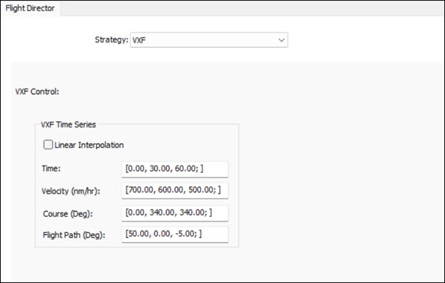
multiple maneuvers
This is an example of a series of time steps.
| Option | Value |
|---|---|
| Fuel State | Cleared |
| Time of Flight | Cleared |
| Downrange | 20 nm |
Inserting an End of Previous Procedure site type
Use an End of Previous Procedure site for your next Dynamic Control procedure.
- Click Insert Procedure After () in the Procedures and Sites toolbar.
- Select End of Previous Procedure () in the Select Site Type list in the Site Properties dialog box.
- Click .
Switching to trim hold
Trim the aircraft to turn and slowly descend for landing.
- Select DynamicControl () in the Select Procedure Type list in the Procedure Properties dialog box.
- Enter Trim Hold Yaw in the Name field.
- Leave the default Trim Hold strategy.
- Select Yaw in the Doublet panel.
- Enter 45 sec in the Length field.
- Set the following in the Basic Stop Conditions panel:
- Click .
- Click .
| Option | Value |
|---|---|
| Fuel State | Cleared |
| Time of Flight | 00:01:00.000 HMS |
| Downrange | Cleared |
Selecting the landing runway
Return to base to perform a touch-and-go landing.
- Select Insert Procedure After () in the Procedures and Sites toolbar.
- Select Runway from Catalog (
 ) in the Select Site Type list in the Site Properties dialog box.
 - Enter Buckley in the Filter field.
- Select the Enter key.
- Select BUCKLEY AFB 14 32 (
 ) under ARINC424 runways ().
 - Click .
Inserting a Landing procedure
A Landing procedure brings an aircraft down from the air to a runway site. Using the Intercept Glideslope approach mode, the aircraft will perform a landing following VFR flight rules; it will use a basic point-to-point methodology to fly to the Initial Approach Fix Range and then descend to landing along the glideslope.
A touch-and-go landing procedure will end the Landing procedure at wheels down. You can then follow this Landing procedure with a Takeoff procedure to simulate a touch-and-go landing. The aircraft will, if needed, accelerate to the takeoff speed as specified in the performance model as part of the subsequent Takeoff procedure.
- Select Landing (
 ) in the Select Procedure Type list in the Procedure Properties dialog box.
 - Set the following options:
- Open the drop-down list in the Enroute Cruise Airspeed panel.
- Select Arrive on landing airspeed (gradual change).
- Click .
- Click .
| Option | Value |
|---|---|
| Name | Buckley Runway |
| Approach Mode | Intercept Glideslope |
| Use runway heading 144 Mag 151 True | Selected |
| Landing Options - Approach Fix Range | 2 nm |
| Landing Options - Runway Altitude Offset | 10 ft |
| Landing Options - Use Terrain for Runway Altitude | Selected |
| Landing Options - Touch and Go | Selected |
| Enroute Options - Use Max Speed When Computing Turn Radii | Selected |
Landing is a standard Aviator procedure. You can easily mix and match Dynamic Control procedures with non-dynamic Aviator procedures, such as Basic Maneuvers, Simple Turns, and Holding patterns, to suit your mission requirements.
Taking off after the touch and go
To complete the touch-and-go landing, you need to take off from the Buckley runway.
- Click Insert Procedure After () in the Procedures and Sites toolbar.
- Note that End of Previous Procedure () is the only available site type, since you selected the Touch and Go landing option for your Landing procedure.
- Click in the Site Properties dialog box.
Selecting the Takeoff procedure
Because you selected Touch and Go for your Landing procedure, the only available procedure is a Takeoff procedure. A Takeoff procedure launches an aircraft from a runway site into the air.
- Set the following options:
- Click .
- Click .
- Review the Mission Profile for situational awareness.
| Option | Value |
|---|---|
| Name | Takeoff from Buckley Runway |
| Runway Altitude Offset | 10 ft |
| Use Terrain for Runway Altitude | Selected |
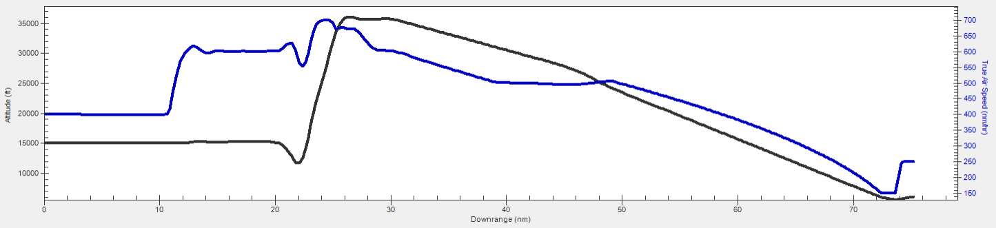
Final Mission Profile
Checking fuel usage
At this point, you can continue to fly your mission. You need to keep an eye on your fuel usage. You could create a report, but you can find useful information while using Aviator.
- Right-click on Takeoff from Buckley Runway (
 ) in the Mission List.
 - Select Profile Data at Final State... in the shortcut menu to open the Profile Data window.
- Scroll down and locate both the Fuel Consumed and Fuel State data providers.
- Close the Takeoff from Buckley Runway dialog box.
The
Fuel Consumed is how much fuel you've used and Fuel State is how much fuel remains. You can use the information to make sure at the beginning of the mission you have enough fuel to fly your entire mission.
Analyzing flight data
An important reason to use six degrees of freedom with the Aviator capability is to obtain analytical data on your aircraft. You will create a custom report focusing on pilot stick control.
Creating a custom report
Create a new report style for your custom report.
- Right-click on DynC_Acft () in the Object Browser.
- Select Report & Graph Manager... (
 ) in the shortcut menu.
 - Select the My Styles (
 ) folder in the Styles panel when the Report & Graph Manager opens.
 - Click Create new report style (
 ) in the Styles toolbar.
 - Enter 6DoF Analysis as the new report name.
- Select the Enter key to set the new report name and to open the report's properties.
Selecting data providers and elements
The Flight Profile By Time data provider has the elements required for your analysis. Flight data is sampled using a constant time step between grid points. You will use the following data provider elements in your custom report:
- Time: The time
- Aileron: The roll axis control input
- Elevator: Longitudinal axis control input
- Rudder: Yaw axis control input
- Throttle (%): The percentage of the maximum thrust required to maintain the flight condition
- True Air Speed: The magnitude of the velocity of the vehicle, where the velocity is measured as observed from the vehicle's central body fixed coordinate system
- Altitude: The altitude value (that is, the magnitude of the relative position vector between the object and its detic subpoint)
- Fuel Consumed: The amount of fuel consumed during the mission in pounds. At mission start, the value is zero.
This report style is only available for Aviator-propagated vehicles.
- Select the Content page when the Properties Browser opens.
- Expand () the Flight Profile By Time () data provider in the Data Providers list.
- Move (
 ) the following data provider elements (
 ) to the Report Contents list in the order shown:
 - Time
- Aileron
- Elevator
- Rudder
- Throttle (%)
- True Air Speed
- Altitude
- Fuel Consumed
- Click to confirm your selections and to close the Properties Browser.
Adjusting the report's time properties
Adjust the time properties of the report to analyze the aircraft in one-second increments.
- Select the Specify Time Properties option in the Time Properties panel.
- Select the Use step size / time bound option.
- Enter 1 sec in the Step size field.
Generating your custom report
Now that you have added the data providers to your report contents and adjusted the step size, generate and review the report.
- Select 6DoF Analysis (
 ) in the My Styles () folder.
 - Click .
- Scroll through the report.
- Close the report and the Report & Graph Manager when finished.
Adding a dynamic data display to the 3D Graphics window
Update your Aircraft object's
- Return to DynC_Acft's () Properties ().
- Select the 3D Graphics – Data Display page.
- Click .
- Select 6DoF Analysis in the Styles list in the Add a Data Display dialog box.
- Click to confirm your selection and to close the Add a Data Display dialog box.
- Open the Font Size drop-down list in the appearance panel.
- Select Medium.
- Click .
This setting is user defined for clarity. If the font is too small or too large on your monitor, select a setting that looks good to you.
You can now view the custom report you created, dynamically, in the 3D Graphics window when you animate the scenario.
Viewing the roll and climb
You can view the entire flight from the Dynamic Control Trim Point until your touch-and-go landing. You can narrow your visualization to each procedure in the Mission List, too. One of the more interesting maneuvers is when you increase speed and use the lateral doublet.
- Return to DynC_Acft's () Properties ().
- Right-click on Fly 90 degrees () in the Mission List.
- Select Set Animation Time in the shortcut menu.
- Bring the 3D Graphics window to the front.
- Right-click on DynC_Acft () in the Object Browser.
- Select Zoom To in the shortcut menu.
- Configure your view so that you are behind DynC_Acft ().
- Click Start (
 ) in the Animation toolbar to watch your lateral doublet maneuver and the follow-on multiple maneuvers.
 - When finished, click Reset (
 ) to reset your scenario.
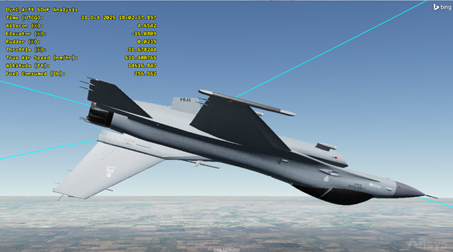
the aircraft rolls, dives, and climbs
Saving your work
Clean up your workspace and close out your scenario.
- Close any open windows except for the 2D and 3D Graphics windows.
- Save () your work.
- Close the scenario when you are finished.
Summary
This scenario was designed to show you how to configure an Aircraft object using Aviator and applying six degrees of freedom to your simulation. You started the simulation using a Dynamic Control Trim Point. You switched to dynamic control using the VXF strategy to increase the aircraft's speed and change its course. Next, you applied a Trim Hold strategy using a Lateral Doublet to roll the aircraft and descend. Switching back to a VXF strategy, you created multiple maneuvers, changing speed, course, and flight path angles. You placed the aircraft back into a Trim Hold to line up for a landing approach, then performed a touch-and-go landing at Buckley SFB. Lastly, you created a custom report that focused on pilot stick control.