STK Premium (Space) or STK Enterprise
You can obtain the necessary licenses for this tutorial by contacting AGI Support at support@agi.com or 1-800-924-7244.
The results of the tutorial may vary depending on the user settings and data enabled (online operations, terrain server, dynamic Earth data, etc.). It is acceptable to have different results.
This lesson requires STK 12.2 or newer to complete it in its entirety. It includes new features introduced in STK 12.2.
Capabilities Covered
This lesson covers the following STK Capabilities:
- STK Pro
- Communications
- STK SatPro
Problem Statement
Engineers and operators need to quickly model dynamically configured communications links between constellations of transmitters and receivers. Complex communication systems may present many potential links for a given receiver or transmitter. They must establish some criterion for determining which transmitter will communicate with which receiver. They also require a quick and easy way to generate a Walker constellation in order to study future satellite constellation designs along with their communication systems. In this lesson, you have a ground site that receives data from a constellation of satellites. You will analyze a link budget based on the following:
- Which satellite provides the strongest carrier to noise ratio to the ground site receiver?
- Which satellite has the highest elevation above the ground site?
- Which satellite provides the strongest received isotropic power to the ground site receiver?
- Which satellite is closest to the ground site?
Additional analysis needs to be based on the radio frequency environment.
Solution
- Use STK's Communications capability to model and analyze a link budget between the ground site and a custom constellation of satellites.
- Use isotropic, omnidirectional antenna patterns to analyze the satellite transmitters and the ground site receiver.
- Use the CommSystem object to select among the link criteria noted above and see how their changes affect a link budget.
What You Will Learn
Upon completion of this tutorial, you will understand the following:
- CommSystem object
- RF Environment Properties
- Link Budgets
Video Guidance
Watch the following video. Then follow the steps below, which incorporate the systems and missions you work on (sample inputs provided).
Create a New Scenario
Create a new scenario for a twenty four (24) hour time period starting 1 Mar 2021 16:00:00.000 UTCG.
- Launch STK (
 ).
). - In the Welcome to STK window, click Create a Scenario (
 ).
). - Enter the following in the New Scenario Wizard:
- When you finish, click .
- When the scenario loads, click Save (
 ). A folder with the same name as your scenario is created for you in the location specified above.
 - Verify the scenario name and location.
- Click .
| Option | Value |
|---|---|
| Name: | CommSys_LinkDef |
| Location: | Default |
| Start: | 1 Mar 2021 16:00:00.000 UTCG |
| Stop: | 2 Mar 2021 16:00:00.000 UTCG |
Save Often!
Turn Off Terrain Server
Terrain will not be used in this analysis.
- Open CommSys_LinkDef's () properties (
 ).
). - Select the Basic - Terrain page.
- Clear the Use terrain server for analysis option.
- Click to accept the changes and close the Properties Browser.
Create a Seed Satellite
The original satellite that is used to create the Walker constellation is referred to as the “Seed” satellite. The satellites generated using the Walker tool are referred to as children. Use the Orbit Wizard to create the “seed” satellite from which the other satellites will be derived.
- Select Satellite (
 ) in the Insert STK Objects tool.
 - Select the Orbit Wizard (
 ) method.
 - Click .
- Set the following on the Orbit Wizard:
- Click .
| Option | Value |
|---|---|
| Type: | Repeating Ground Trace |
| Satellite Name: | Satellite |
| Approximate Altitude: | 750 km |
Satellite Transmitter
The Simple Transmitter model is convenient when you do not have all the information necessary to model the transmitter in detail; for example, during the system engineering process. Insert a default Transmitter object which is a Simple Transmitter Model.
- Select Transmitter (
 ) in the Insert STK Objects tool.
 - Select the Insert Default () method.
- Click .
- Select Satellite () on the Select Object window.
- Click .
- Right-click the Transmitter () in the Object Browser.
- Select Rename.
- Rename Transmitter1 () Transmitter.
Walker Constellations
The Walker Tool makes it easy to generate a Walker constellation using the Two Body, J2, J4, or SGP4 orbit propagators. Open the Walker tool by highlighting the satellite in the Object Browser and selecting Walker... from the Satellite menu.
- Right-click on Satellite () in the Object Browser.
- Select Satellite.
- Select Walker...
- Set the following in the Walker Tool:
- Click .
- Click when finished propagating the walker constellation.
| Option | Value |
|---|---|
| Type: | Delta |
| Number of Sats per Plane | 2 |
| Number of Planes: | 12 |
| Inter Plane Spacing: | 1 |
Walker Satellite Relationships
When a Walker constellation is created, each child has the same base name as the seed satellite plus two numbers. The first number identifies the plane in which the satellite resides and the second identifies the satellite's position in the plane. For instance, here we define a Walker constellation with twelve planes and two satellites per plane. Satellite122 would be the second satellite in the twelfth plane. If the seed satellite has sub-objects such as transmitters, the sub-objects are also created for each of the child satellites.
The seed satellite (Satellite) and Satellite011 are identically configured satellites. Keep this in mind when analyzing your scenario.
Turn off the seed satellite visually but not analytically.
- Select Satellite () in the Object Browser.
- Clear the check box next to Satellite ().
Communications Facility
Insert a Facility object to model the ground station.
- Select Facility (
 ) in the Insert STK Objects tool.
 - Select the Define Properties () method.
- Click .
- Select the Basic - Position page.
- Set the following:
- Click .
- Rename the Facility () Comm_Fac.
| Option | Value |
|---|---|
| Latitude: | 41.1084 deg |
| Longitude: | -95.911 deg |
| Height Above Ground: | 10 ft |
Facility Receiver
The Simple Receiver model is convenient when you do not have all the information necessary to model the receiver in detail; for example, during the system engineering process. Insert a default Receiver object which is a Simple Receiver Model.
- Select Receiver (
 ) in the Insert STK Objects tool.
 - Select the Insert Default () method.
- Click .
- Select Comm_Fac () on the Select Object window.
- Click .
- Rename Receiver1 () Receiver.
The CommSystem Object
The CommSystem object models dynamically configured communications links between constellations of transmitters and receivers.
To set up a CommSystem object, you must first organize the relevant communication assets into groups:
- The transmitter(s) in the communications link of interest
- The receiver(s) in the communications link of interest
Insert Constellation Objects
Insert two Constellation Objects, one for the transmitters and one for the receivers. These will be used to define the communication assets in the CommSystem Object.
- Select Constellation (
 ) in the Insert STK Objects tool.
 - Select the Insert Default () method.
- Click .
- Repeat the above steps to insert a second Constellation ().
- Rename the new Constellation objects Receivers and Transmitters.
Define Receiver Constellation
- Open Receivers' () properties ().
- Select the Basic - Definition page.
- Select Receiver () in the Available Objects list.
- Click Move (
 ) to move the Receiver () to the Assigned Objects list.
 - Click .
Define Transmitters Constellation
- Open Transmitters' () properties ().
- Select Transmitter () in the Selection Filter list.
- Click Move () to move the tranmitters to the Assigned Objects list.
- Select Satellite/Transmitter () in the Assigned Objects list.
- Click Move left (
 ) to remove Satellite/Transmitter () from the Assigned Objects list. This is the seed satellite's transmitter and you don't want to use it in your analysis.
 - Click .
Set Up the CommSystem Object
Set up the CommSystem object focusing on the following:
- Transmit: Select the Transmitters () constellation to carry out the transmit function in the communications link analysis.
- Receive: Select the Receivers () constellation to carry out the receive function in the CommSystem.
- Link Definition: Select the link criteria and specify whether the selected criterion is to constrain the receiving or transmitting constellations in the CommSystem.
Add CommSystem Object to Insert STK Objects tool
Ensure the CommSystem (![]() ) object appears in the Insert STK Objects tool.
) object appears in the Insert STK Objects tool.
- Click on the Insert STK Objects tool.
- In the New Object list, select the object you want to add.
- Click .
Insert a CommSystem Object
Insert a CommSystem (![]() ) object into your scenario.
) object into your scenario.
- Select CommSystem (
 ) on the Insert STK Objects tool.
 - Select the Insert Default () method.
- Click .
Set CommSystem's Transmit Function
Select the Transmitters (![]() ) constellation to carry out the transmit function in the system.
) constellation to carry out the transmit function in the system.
- Open CommSystem1's () properties ().
- Select the Basic - Transmit page.
- Select Transmitters () in the Available Constellations list.
- Click Move () to move it to the Assigned Constellations list.
Set CommSystem's Receive Function
Select the Receivers (![]() ) constellation to carry out the receive function in the system.
) constellation to carry out the receive function in the system.
- Select the Basic - Receive page.
- Select Receivers () in the Available Constellations list.
- Click Move () to move it to the Assigned Constellations list.
- Click to accept the changes and keep the Properties Browser open.
Define the Basic Link Definition
Complex communication systems may present many potential links for a given receiver or transmitter. You must establish some criterion for determining which transmitter will communicate with which receiver.
Use the Link Definition page to select among the link criteria and specify whether the selected criterion is to constrain the receiving or transmitting constellations in the CommSystem.
- Select the Basic - Link Definition page.
- Set the following:
- Click .
- Save () your scenario.
| Option | Value |
|---|---|
| Constraining Constellations | Receive |
| Link Selection Criteria | Maximum Elevation |
Maximum elevation selects the non-constraining object that has the highest elevation angle with reference to the constraining object.
Display CommSystem Relationships
View the CommSystem in the 3D Graphics Window.
- Bring the 3D Graphics window to the front.
- Right-click on Comm_Fac () in the Object Browser.
- Select Zoom To.
- Use your mouse to zoom out until you have a good view of Comm_Fac and the orbital planes.
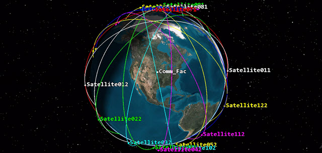
Communications Facility and Orbital Planes
Compute CommSystem
After defining the CommSystem object, select Compute Data from the CommSystem menu to process link information.
- Select CommSystem1 () in the Object Browser.
- Select CommSystem on the STK menu bar.
- Select Compute Data.
There is a calculation progress bar in the lower right corner of STK.
Generate Link Budget Report
Generate an STK pre-built link budget report.
- Right-click on CommSystem1 () in the Object Browser when the calculation is complete.
- Select Report & Graph Manager... (
 ).
). - Select Link Information Detailed (
 ) in the Installed Styles folder.
 - Click .
- Scroll across the report to become familiar with the Link Information data provider elements used in the detailed link budget.
- Scroll back to the left then scroll down.
- Notice how the transmitter IDs change based on maximum elevation. This doesn't mean that's the only transmitter that the receiver has access to, it simply means at that moment in time, that's the transmitter with the highest elevation to the receiver.
- Close the report when finished.
Your current link definition criteria selection is maximum elevation. If you look at the top of the report, there is a transmitter ID assigned to each satellite's transmitter. Looking below at the detailed link budget, each line is reporting data on the receiver that has the highest elevation in regards to the receiver on the ground at that time.
Create a Custom Report
Create a custom report using selected CommSystem data providers and elements. This report will focus on your CommSystem link definition criteria selections:
- Transmitter Information: The transmitter information has the name and ID of the transmitters
- Link Information: Link information provides the link budget for the CommSystem
- Return to the Report & Graph Manager.
- Select the CommSys_LinkDef Styles folder (
 ) in the Styles list.
 - Click Create new report style (
 ).
). - Rename the report "CommSystem Report".
- Press Enter on your keyboard to open CommSystem Report's (
 ) properties ().
Set the Report Properties - Section 1
Create Section 1.
- Select the Content page.
- Expand (
 ) Transmitter Information in the Data Providers section.
 - Select Transmitter Name.
- Click Move () to move the element to the Report Contents list.
- Select Transmitter ID.
- Click Move () to move the element to the Report Contents list.
Set the Report Properties - Section 2
Create Section 2.
- Expand () Link Information in the Data Providers section.
- Hold the Ctrl key down on your keyboard and select the following elements:
-
Click Move (
) to move the elements to the Report Contents list. - Click .
| Option |
|---|
| Time |
| Link to ID |
| Rcvd Iso. Power |
| C/N |
Generate the CommSystem Report
The data providers used in your custom report are similar to the ones used in the Link Information detailed report. However, you only selected the elements you are focusing on in the CommSystem object.
- Retuen to the Report & Graph Manager.
- Select CommSystem Report () in the CommSys_LinkDef Styles folder
- Click .
- Scroll through the report to become familiar with the data.
- Leave the report open.
Just like the Link Budget Detailed report, you are seeing the data on the receiver that has the highest elevation in regards to the receiver on the ground at that time.
View the Accesses
Look at the accesses between the receiver on the ground and the satellite transmitters based on maximum elevation.
- Right-click on the first access time in your report.
- Select Time.
- Select Set Animation Time.
- Bring the 3D Graphics window to the front.
- Click Decrease Time Step (
 ) in the animation toolbar until you set the Time Step: value to 3.00 sec.
 - Click Start (
 ) to animate the scenario.
 - Watch the access line jump between transmitters based on maximum elevation.
- Click Reset (
 ) when finished.
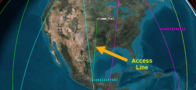
Maximum Elevation Access Line
Update Link Selection Criteria to Minimum Range
Minimum range selects the non-constraining object with the minimum distance to the constraining object.
- Return to CommSystem1's () properties ().
- Select the Basic - Link Definition page.
- Change the Link Selection Criteria to Minimum Range.
- Click .
Refresh the CommSystem Report
As you make link definition changes, some of the changes will be very subtle. You won't do this now, but you can save the reports as external text files or .csv files and compare values based on time.
- Return to the CommSystem Report.
- Click Refresh (
 ).
). - Look at the report. Now you are seeing the data on the receiver that has the minimum range in regards to the receiver on the ground at that time.
Be patient. The CommSystem (![]() ) object must be recomputed.
) object must be recomputed.
Update Link Selection Criteria to Maximum RIP
Maximum RIP selects the non-constraining object with the maximum RIP (received isotropic power) to the constraining object. Received isotropic power is the power at the receiver before the pre-receive gains/losses and the receiver antenna gain added (in dBW). It is equal to the EIRP with all the channel losses as well as the bandwidth overlap applied.
- Return to CommSystem1's () properties ().
- Select the Basic - Link Definition page.
- Change the Link Selection Criteria to Maximum RIP.
- Click .
Refresh the CommSystem Report
- Return to the CommSystem Report.
- Click Refresh ().
- Look at the data in the report.
Model Rain
Environmental factors can affect the performance of a communications link. So that you don't have to wait a long time for each change, you will only apply the rain model to the analysis. Rain models are used to estimate the amount of degradation (or fading) of the signal when passing through rain.
- Open CommSys_LinkDef's () properties ().
- Select the RF - Environment page.
- Select the Rain, Cloud & Fog tab.
- Select Use in the Rain Model section.
- Leave the default ITU (International Telecommunication Union) model.
- Click .
Refresh the CommSystem Report
- Return to the CommSystem Report.
- Click Refresh ().
- Look at the data in the report.
The order of the satellites may not have changed visually, but there were definite changes in Rcvd. Iso. Power (dBw) and C/N (dB).
Update Link Selection Criteria to Maximum C/N
Maximum C/N selects the non-constraining object with the maximum C/N (carrier to noise ratio) to the constraining object. The carrier to noise ratio (C/N) where C is the carrier power and N = kTB (Boltzmann's constant x system temperature x bandwidth) is the noise power.
- Return to CommSystem1's () properties ().
- Select the Basic - Link Definition page.
- Change the Link Selection Criteria to Maximum C/N.
- Click .
Refresh the CommSystem Report
- Return to the CommSystem Report.
- Click Refresh ().
- Look at the data in the report.
You might not have seen a noticeable change in the report. Again, you would want to compare changes using external reports.
Use Refraction in Access Computations
By default, atmospheric refraction is not considered when computing the relative apparent position in Access. Turn on this capability.
- Open Receiver's () properties ().
- Select the Basic - Refraction page.
- Select Use Refraction in Access Computations.
- Select the ITU model as the Refraction Model.
- Click .
Refresh the CommSystem Report
Keep an eye on the first access Link To ID value.
- Return to the CommSystem Report.
- Click Refresh ().
- Look at the data in the report.
A different satellite now has the maximum C/N based on the first access when applying refraction to the analysis.
Save Your Work
- When finished, close any open reports, properties and the Report & Graph Manager.
- Save () your work.
Summary
You set up a ground station receiving transmissions from 24 satellites that were created using the Walker tool. Separate STK Constellation objects allowed you to group the transmitters and the receiver which were used by the CommSystem object. In the CommSystem object, you used the receiver constellation as your constrained receiver. Using link definition, you analyzed Maximum C/N, Maximum Elevation, Maximum RIP and Minimum Range from the transmitters to the receiver at a given time. You should see the power of being able to determine which transmitter in a constellation of satellites provides the best RIP or C/N at any given time. You didn't use other environmental factors such as atmospheric absorption or compute receiver system noise temperature but all factors should be taken into account for more precise analysis.
On Your Own
Throughout the tutorial, hyperlinks were provided that pointed to in depth information pertaining to the scenario. Now's a good time to go back through this tutorial and view that information. You could switch things and create multiple ground sites and one satellite to determine which ground site provides the best link analysis. You could keep this scenario as is, but add multiple receivers on the ground and determine, in a network, which receiver at a given time has the best link based on your link definition.
For further study using the CommSystem object, check out these lessons: